warning - hitchfinderstores
TRANSCRIPT

BX22532009-14 Honda Fit & Fit Sport
Installation Instructions
405-0255 Rev B Page 1 of 10 5/1/14
1. Blue Ox® towing products and accessories are intended to be installed by Blue Ox® Dealers who are familiar with our products and have the equipment and knowledge necessary to do “fit work”. If needed, Blue Ox® Dealers can be found at www.blueox.com or by contacting our Customer Care Department at (402) 385-3051.
2. Many Blue Ox® baseplates are designed to use existing holes and hardware to mount the baseplate to the towed vehicle. Even though bolts are there, do not assume they are adequate for baseplate mounting. Always use the hardware supplied in the hardware kit and existing hardware as specified in the installation instructions.
Reference your vehicle owner’s manual for manufacturer’s towing
specifications.
Attachment Tab Height: 13-1/2”
Attachment Tab Width: 24”
Serial Number
If the front of your vehicle looks different than this, please contact us at (402)385-3051. !
Failure to read and follow these instructions could result in separation of the towed vehicle from the tow bar, causing property damage,
loss of towed vehicle, personal injury or death.
WARNING
Bolt Size Grade 5 Grade 81/4” 10 145/16” 19 293/8” 33 477/16” 54 781/2” 78 1195/8” 154 2303/4” 257 380
Bolt Torque Specifications Torque in Foot-Pounds for Inch Bolts
Bolt Torque Specifications Torque in Foot-Pounds for Metric Bolts
Bolt Size Grade 8.8 Grade 10.96MM 6 88MM 16 22
10MM 31 4012MM 54 7014MM 89 11716MM 161 23018MM 222 318
Please read BOTH these Installation Instructions and the General Instructions prior to installing or operating this equipment.

BX22532009-14 Honda Fit & Fit Sport
Installation Instructions
405-0255 Rev B Page 2 of 10 5/1/14
Instruction Notes: The fascia and bumper core are removed and reinstalled for the baseplate installation. Some drilling and trimming is required.
Place all components that are removed on a flat, sturdy surface. All items will be reinstalled unless otherwise noted after the baseplate is installed.
The dimensional variations between otherwise identical vehicles can be considerable. While the baseplate was designed for easy installation, it may be necessary to tailor the baseplate slightly to compensate for vehicle manufacturer’s tolerances.
The BX8869 Tail Light Wiring Kit is recommended for this vehicle.
Drill a hole according to the tail light wiring kit instructions.
NOTICE• Handling of some cosmetic parts when installing this product may require the use of protective
covers, rags, specialty tools, etc. to prevent damage. • When using power drills be aware of the dangers of torque and drill bit length.• When using a reciprocating saw be aware of objects behind the cutting surface.• Use a good quality paint to spray cut edges of frame to prevent rusting.• Be sure that ALL electrical connections are plugged in and accessories are functioning properly
before reinstalling the fascia.• The baseplate is computer tested to your vehicle’s GVWR, exceeding this weight will void the
manufacturer’s warranty.• Be sure to use Loctite® Red on all bolts before tightening. Tighten all bolts according to the
torque chart provided.• Dealer or installer be certain the user receives these instruction sheet.• If the baseplate is in an accident, it must be replaced. DO NOT use it again! An accident can
cause unseen damage and using it again could result in more damage or serious injury. DO NOT use the baseplate if it is damaged or missing parts.

BX22532009-14 Honda Fit & Fit Sport
Installation Instructions
405-0255 Rev B Page 3 of 10 5/1/14
Item No. Part No. Description Qty.1.................................61-6723 .............................BX2253 Baseplate ...........................................................12.................................62-3469 .............................Attachment Tab Assembly with Hole ...............................23.................................101-5822 ...........................4 Way Connector Adapter ...............................................24.................................102-6946 ...........................Spacer Plate ....................................................................25.................................102-7134 ...........................Breakaway Bracket .........................................................16.................................201-0050 ...........................1/4”-20 x 3/4” Hex Head Bolt, Grade 5, ZP .....................27.................................201-0192 ...........................#10-32 1/2” Round Slotted Head Screw ..........................28.................................201-0368 ...........................3/8”-16 x 1-1/4” Hex Head Bolt, Grade 5, ZP ..................49.................................201-0440 ...........................3/8”-16 x 1-1/2” Hex Head Bolt, Grade 5, ZP ..................210...............................201-0979 ...........................#12-14 x 1” Self Drilling Screw, ZP ..................................211 ...............................202-0047 ...........................#10-32 Hex Nut ...............................................................212...............................202-0090 ...........................3/8”-16 Hex Nylon Insert Lock Nut, ZP ............................613...............................202-0102 ...........................1/4”-20 Hex Nylon Nut, ZP ..............................................214...............................203-0054 ...........................#10 Lock Washer, ZP ......................................................215...............................226-0046(not shown) ........Class III Safety Cables ....................................................216...............................229-0359(not shown) ........3/8” Quicklink, ZP ............................................................217...............................290-0437(not shown) ........Black Cap Plug Receiver .................................................2
Tools Required
Large Vise GripFlat Screwdriver
Utility KnifePhillips Screwdriver
Torque WrenchDrill
Tape MeasureLoctite® RED13/32” Drill Bit12MM Socket9/16” Socket9/16” Wrench
10
11
4
2
9
8
13
3
12
6
1
6-Way Connector
5
Breakaway
714
4-Way Connector
Important:Use only genuine factory replacement parts on your baseplate. Do NOT substitute homemade or non-typical parts. If a bolt is lost or in need of replacement, for your safety and the preservation of your baseplate, be sure to use a replacement bolt of the same grade (In most cases it will be Grade 5, please reference the parts list above). Replacement parts may be ordered through your nearest Blue Ox® Dealer or Distributor. Failing to follow and/or altering these installation instructions in either installation or required equipment will void the manufacturer’s warranty.

BX22532009-14 Honda Fit & Fit Sport
Installation Instructions
405-0255 Rev B Page 4 of 10 5/1/14
1. On top of the fascia, using a flat screwdriver, remove eight (8) push pins.
1 2
2. Just inside wheel well, on edge of fascia, use the Phillips screwdriver to remove one (1) screw. Do this to both sides of the vehicle. Set screws aside to be reinstalled later.
3. Using a flat screwdriver, remove two (2) push pins from the bottom corner of the fascia. Do this to both sides of the vehicle.
4
3
4. Underneath in the center, using a flat screwdriver, remove three (3) push pins.
5
5. Using a Phillips screwdriver, remove two (2) screws holding the fascia. Do this to both sides of the vehicle.

BX22532009-14 Honda Fit & Fit Sport
Installation Instructions
405-0255 Rev B Page 5 of 10 5/1/14
7A 7B
7. Using the 12MM socket, remove four (4) bolts from the metal bumper, three (3) on the top and one (1) on the bottom. Do this to both sides of the vehicle.
8. Using the utility knife, trim the air dam under the bumper on the driver’s side as shown in 8A and the passenger side as in 8B.
8A 8B
6
6. Use a flat screwdriver to gently pry the three tabs along the side of the vehicle. Underneath the headlight, slightly lift up the four (4) plastic tabs, one (1) at a time, as the fascia is removed. Do this to both sides of the vehicle. Carefully set the fascia aside.

BX22532009-14 Honda Fit & Fit Sport
Installation Instructions
405-0255 Rev B Page 6 of 10 5/1/14
10
10. Slide the baseplate on and align with the top existing hole which has been drilled out. Fasten tight with a 3/8” x 1-1/4” bolt and 3/8” hex nut. Be sure the baseplate is level with the vehicle and this will effect how baseplate comes through fascia opening. Use the baseplate as a template to drill the other two holes. Do this on both sides.
11. In the top two (2) holes, insert 1-1/4” bolts (11A white arrows). On the inside of the frame end, attach to a plate with the narrow end to the front with 3/8” lock nuts (11B white arrows). In the bottom hole, insert 1-1/2” bolts (11A gray arrow) and attach to 3/8” lock nuts underneath on the webbing (11B gray arrow). Do this on both sides.
11A
11B
9. Using a 13/32” drill bit, drill out the top existing hole. Do this on both sides. Note: On passenger side drill hole out at an angle or remove the washer fluid reservoir to drill hole straight.
9
BX22532009-14 Honda Fit & Fit Sport
Installation Instructions
405-0255 Rev B Page 7 of 10 5/1/14
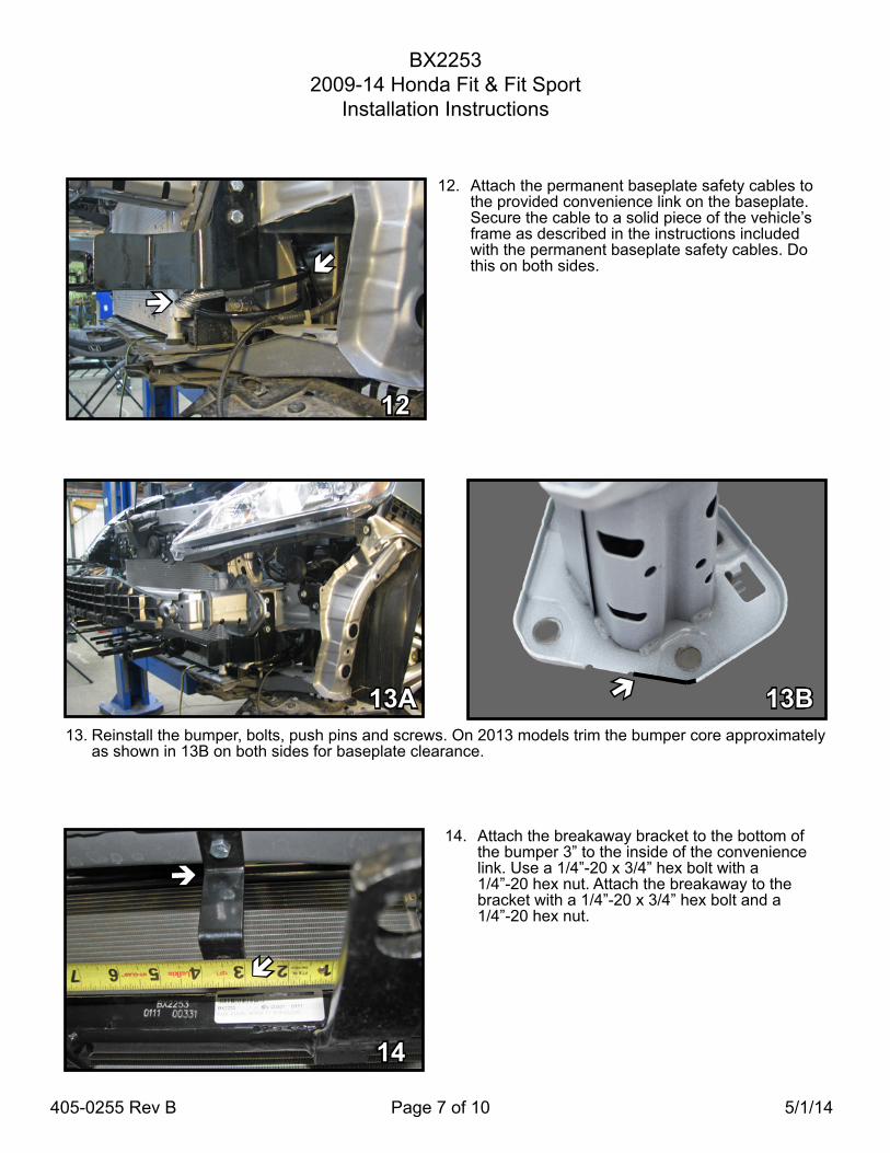
14
14. Attach the breakaway bracket to the bottom of the bumper 3” to the inside of the convenience link. Use a 1/4”-20 x 3/4” hex bolt with a 1/4”-20 hex nut. Attach the breakaway to the bracket with a 1/4”-20 x 3/4” hex bolt and a 1/4”-20 hex nut.
13A13. Reinstall the bumper, bolts, push pins and screws. On 2013 models trim the bumper core approximately
as shown in 13B on both sides for baseplate clearance.
13B
12
12. Attach the permanent baseplate safety cables to
the provided convenience link on the baseplate. Secure the cable to a solid piece of the vehicle’s frame as described in the instructions included with the permanent baseplate safety cables. Do this on both sides.

BX22532009-14 Honda Fit & Fit Sport
Installation Instructions
405-0255 Rev B Page 8 of 10 5/1/14
15B
15. Trim foglights as shown above for your particular year of vehicle. Pictures 15A and 15C show area to be trimmed and pictures 15B and 15D show the foglights with the trimming completed.
15A
2 0 0 9 - 2 0 1 1 Models
2 0 1 2 Models
15D 15C
BX22532009-14 Honda Fit & Fit Sport
Installation Instructions
405-0255 Rev B Page 9 of 10 5/1/14
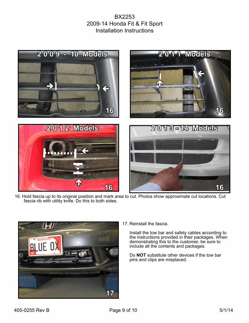
17. Reinstall the fascia.
Install the tow bar and safety cables according to the instructions provided in their packages. When demonstrating this to the customer, be sure to include all the contents and packages.
Do NOT substitute other devices if the tow bar pins and clips are misplaced.
17
2 0 1 1 Models
2 0 0 9 - 10 Models
16. Hold fascia up to its original position and mark area to cut. Photos show approximate cut locations. Cut fascia rib with utility knife. Do this to both sides.
16 16
2 0 1 2 Models
16
16
2 0 1 3 - 14 Models

BX22532009-14 Honda Fit & Fit Sport
Installation Instructions
405-0255 Rev B Page 10 of 10 5/1/14
2009 - Shown with removable tabs installed 2013 - Shown with removable tabs installed
CUSTOMER SERVICE COMMITMENT
Blue Ox® is committed to providing you with exceptional customer care throughout your lifetime with our products. Our team is here to assist you with any questions you may have regarding the performance of your product. Simply call (402) 385-3051 and you can speak with our customer care team.
Additionally, please visit our website to see which rallies our Destination America team will be attending. For a nominal fee, our service technician will service your towing system to ensure it’s in proper working condition. Also, as a commitment to our customers, should you visit our factory, you can stay at our full service Blue Ox® campground at no charge along with enjoying a factory tour.
Again, thank you for being our customer and for the confidence you have shown in the performance of our products. It is because of customers like you we enjoy the success we have today.
© 2014 Blue Ox One Mill Road, Industrial Park
Pender, Nebraska 68047Phone: (402) 385-3051
Fax: (402) 385-3360www.blueox.com