warranty rranty - hobbicomanuals.hobbico.com/top/topa0950-manual-v1_1.pdfother written documentation...
TRANSCRIPT

WARRANTY.....Top Flite® Models guarantees this kit to be free from defects in both material and workmanship at the date of purchase. This warranty does not cover any component parts damaged by use or modifi cation. In no case shall Top Flite’s liability exceed the original cost of the purchased kit.Further, Top Flite reserves the right to change or modify this warranty without notice.
In that Top Flite has no control over the fi nal assembly or material used for fi nal assembly, no liability shall be assumed nor accepted for any damage resulting from the use by the user of the fi nal user-assembled product. By the act of using the user-assembled product, the user accepts all resulting liability.
If the buyer is not prepared to accept the liability associated with the use of this product, the buyer is advised to return this kit immediately in new and unused condition to the place of purchase.
To make a warranty claim send the defective part or item to Hobby Services at the address:
Include a letter stating your name, return shipping address, as much contact information as possible (daytime telephone number, fax number, e-mail address), a detailed description of the problem and a photocopy of the purchase receipt. Upon receipt of the package the problem will be evaluated as quickly as possible.
READ THROUGH THIS MANUAL BEFORE STARTING CONSTRUCTION. IT CONTAINS IMPORTANT INSTRUCTIONS AND WARNINGS CONCERNING THE ASSEMBLY AND USE OF THIS MODEL.
Hobby Services3002 N. Apollo Dr., Suite 1Champaign, IL 61822 USA
Top Flite Models Champaign, IL Telephone (217) 398-8970, Ext. 5 airsupport@top-fl ite.com
Entire Contents © Copyright 2008 TOPZ0950 for TOPA0950 V1.1
™
RRANTY Top Flite® Models guarantees this kit to be®
If the buyer is not prepared to accept the liability associated with the use of thisproduct the buyer is advised to return this kit immediately in new and unused
™
Wingspan: 64.5 in [1640mm]Wing Area: 721 sq in [46.5 dm2]Weight: 8.75 – 10 lb [3970 – 4540g]Wing Loading: 28 – 32 oz/ft2 [85 – 98g/dm2]Length: 56 in [1420mm]Radio: 6+ channel with 8 servosEngine: .60 – .91 cu in [10 – 15cc] two-stroke,
.90 – 1.20 cu in [15 – 20cc] four-stroke

TABLE OF CONTENTSINTRODUCTION .............................................................. 2AMA ................................................................................. 2SAFETY PRECAUTIONS ................................................ 2DECISIONS YOU MUST MAKE ....................................... 3 Building Stand ............................................................... 3 Radio Equipment ........................................................... 3 Engine Recommendations ............................................ 3 Landing Gear Options ................................................... 3 Scale Competition ......................................................... 3 ADDITIONAL ITEMS REQUIRED .................................. 4 Hardware & Accessories ............................................... 4 Adhesives & Building Supplies ...................................... 4 Optional Supplies & Tools .............................................. 4IMPORTANT BUILDING NOTES ..................................... 4KIT INSPECTION ............................................................. 5 Kit Contents ................................................................... 5ORDERING REPLACEMENT PARTS ............................. 5 Replacement Parts List ................................................. 5METRIC CONVERSIONS ................................................ 5PREPARATIONS .............................................................. 7ASSEMBLE THE WING ................................................... 7 Hinge the Ailerons & Flaps ............................................ 7 Mount the Servos .......................................................... 9 Install the Aileron & Flap Pushrods ............................. 10 Join the Wing Panels ................................................... 11 Install the Retracts ....................................................... 13 Install the Retract Servo .............................................. 14 Finish the Wing ............................................................ 14 Optional Strut Cover Installation .................................. 15ASSEMBLE THE TAIL SECTION .................................. 15 Install the Horizontal Stabilizer, Elevators, Servos & Linkages ...................................................... 15 Install the Rudder, Tail Wheel & Linkages ................... 18INSTALL THE POWER SYSTEM & RECEIVER ............ 19 Glow Engine Installation .............................................. 19 Install the Receiver & Battery ...................................... 21FINISH THE MODEL ...................................................... 22 Install the Cowl ............................................................ 22 Install the Cockpit & Canopy ....................................... 23 Install the Propeller & Spinner ..................................... 24 Optional Pneumatic Retracts ....................................... 25 Apply the Decals ......................................................... 25GET THE MODEL READY TO FLY ................................ 25 Check the Control Directions ....................................... 25 Set the Control Throws ................................................ 26 Balance the Model (C.G.) ............................................ 26 Balance the Model Laterally ........................................ 27PREFLIGHT ................................................................... 27 Identify Your Model ...................................................... 27
Charge the Batteries ................................................... 27 Balance Propellers ...................................................... 27 Ground Check ............................................................. 27 Range Check ............................................................... 27ENGINE SAFETY PRECAUTIONS ................................ 28AMA SAFETY CODE (EXCERPTS) .............................. 28 General ........................................................................ 28 Radio Control .............................................................. 28CHECK LIST .................................................................. 29FLYING ........................................................................... 29 Fuel Mixture Adjustments ............................................ 29 Takeoff ......................................................................... 29 Flight ............................................................................ 30 Landing ........................................................................ 30
INTRODUCTION
Following the great success of the .60-sized Top Flite P-51 Mustang kit comes the same beautiful model in ARF form! The sky is the limit for the amount of additional detail that could be added during the building process to make the P-51 Mustang ARF a model even the most serious scale-minded builder could appreciate. The model assembles in as little as 15 to 20 hours with time-consuming painting tasks expertly complete out of the box.
For the latest technical updates or manual corrections to the P-51 Mustang ARF visit the Top Flite web site at www.top-fl ite.com. Open the “Airplanes” link, then select the P-51 Mustang ARF. If there is new technical information or changes to this model a “tech notice” box will appear in the upper left corner of the page.
AMA
We urge you to join the AMA (Academy of Model Aeronautics) and a local R/C club. The AMA is the governing body of model aviation and membership is required to fl y at AMA clubs. Though joining the AMA provides many benefi ts, one of the primary reasons to join is liability protection. Coverage is not limited to fl ying at contests or on the club fi eld. It even applies to fl ying at public demonstrations and air shows. Failure to comply with the Safety Code (excerpts printed in the back of the manual) may endanger insurance coverage. Additionally, training
programs and instructors are available at AMA club sites to help you get started the right way. There are over 2,500 AMA chartered clubs across the country. Contact the AMA at the address or toll-free phone number below:
Academy of Model Aeronautics5151 East Memorial Drive
Muncie, IN 47302-9252Tele. (800) 435-9262Fax (765) 741-0057
Or via the Internet at:http://www.modelaircraft.org
IMPORTANT!!! Two of the most important things you can do to preserve the radio controlled aircraft hobby are to avoid fl ying near full-scale aircraft and avoid fl ying near or over groups of people.
PROTECT YOUR MODEL, YOURSELF & OTHERS.
FOLLOW THESE IMPORTANT SAFETY PRECAUTIONS
1. Your P-51 Mustang ARF should not be considered a toy, but rather a sophisticated, working model that functions very much like a full-size airplane. Because of its performance capabilities, the P-51 Mustang ARF, if not assembled and operated correctly, could possibly cause injury to yourself or spectators and damage to property.
2. You must assemble the model according to the instructions. Do not alter or modify the model, as doing so may result in an unsafe or unfl yable model. In a few cases the instructions may differ slightly from the photos. In those instances the written instructions should be considered as correct.
3. You must take time to build straight, true and strong.
4. You must use an R/C radio system that is in fi rst-class condition, and a correctly sized engine and components (servos, servo extension, etc.) throughout the building process.
2

5. You must correctly install all R/C and other components so that the model operates correctly on the ground and in the air.
6. You must check the operation of the model before every fl ight to insure that all equipment is operating and that the model has remained structurally sound. Be sure to check clevises or other connectors often and replace them if they show any signs of wear or fatigue.
7. If you are not an experienced pilot or have not fl own this type of model before, we recommend that you get the assistance of an experienced pilot in your R/C club for your fi rst fl ights. If you’re not a member of a club, your local hobby shop has information about clubs in your area whose membership includes experienced pilots.
8. While this kit has been fl ight tested to exceed normal use, if the plane will be used for extremely high stress fl ying, such as racing, or if an engine larger than one in the recommended range is used, the modeler is responsible for taking steps to reinforce the high stress points and/or substituting hardware more suitable for the increased stress.
We, as the kit manufacturer, provide you with a top quality, thoroughly tested kit and instructions, but ultimately the quality and fl yability of your fi nished model depends on how you build it; therefore, we cannot in any way guarantee the performance of your completed model, and no representations are expressed or implied as to the performance or safety of your completed model.
Remember: Take your time and follow the instructions to end up with a well-built model that is straight and true.
DECISIONS YOU MUST MAKE
This is a partial list of items required to fi nish the P-51 Mustang ARF that may require planning or decision making before starting to build. Order numbers are provided in parentheses.
BUILDING STAND
A building stand or cradle comes in very handy during the build. We use the Robart Super Stand II (ROBP1402) for most of our projects in R&D, and it can be seen in pictures throughout this manual.
RADIO EQUIPMENT
A 6-channel radio system such as a Futaba® 6EXAS with a standard receiver and six standard size servos with a minimum torque of 44 oz-in [3.2 kg-cm] are required for the control surfaces of the P-51 Mustang ARF. The included mechanical retracts require a 180° retract servo. If you will be installing optional pneumatic retracts, a micro servo will be required to operate the air valve. One standard torque servo such as an S3003 is required for the throttle. Two 24" [610mm] servo extensions (aileron servos) and two Y-harnesses (aileron and fl ap servos) are also required. A receiver battery pack with a minimum capacity of 1000mAh is recommended. Order numbers are provided as follows:
❏ Futaba S9001 Servo Aircraft Coreless BB (FUTM0075)
❏ Futaba S136G Compact Retract Servo (FUTM0670)❏ Futaba S3003 Servo Standard (FUTM0031)❏ Hobbico® Extension 24" Futaba J (HCAM2200)❏ Futaba 6" Dual Servo Extension J (FUTM4130)❏ Futaba NR4RB Receiver NiCd 4.8V 1000mAh (FUTM1380)
Optional:❏ Futaba S3115 Micro Precision Servo (FUTM0415)
ENGINE RECOMMENDATIONS
A .60 to .91 cu in [10 to 15cc] two-stroke or .90 to 1.20 [15 to 20cc] four-stroke engine is required. An O.S.® FS-91 Surpass™ II four-stroke engine installation is shown in this manual.
❏ O.S. FS-91 Surpass II (OSMG0896)
LANDING GEAR OPTIONS
The P-51 Mustang ARF includes mechanical retracts. Optional pneumatic retracts can also be installed. Part numbers are provided below.
❏ Robart® 605HD 90° main landing gear w/3/16" wire (ROBQ0005)❏ Robart 188VR standard air control kit (ROBQ2302)❏ Robart 190 air line quick disconnects (ROBQ2395)
SCALE COMPETITION
Though the Top Flite P-51 Mustang ARF may not have the same level of detail as an “all-out” scratch-built competition model, it is a scale model nonetheless and is therefore eligible to compete in the Fun Scale class in AMA competition (we receive many favorable reports of Top Flite models in scale competition!). To receive the fi ve points for scale documentation, the only proof required that a full-size aircraft of this type in your paint/markings scheme did exist is a single sheet such as a kit box cover from a plastic model, a photo, or a profi le painting, etc. If the photo is in black and white
3

other written documentation of color must be provided. Contact the AMA for a rule book with full details.
If you would like photos of the full-size P-51D Mustang for scale documentation, or if you would like to study the photos to add more scale details, photo packs are available from:
Bob’s Aircraft Documentation3114 Yukon Ave
Costa Mesa, CA 92626
Telephone: (714) 979-8058Fax: (714) 979-7279
E-mail: www.bobsairdoc.com
ADDITIONAL ITEMS REQUIRED
HARDWARE & ACCESSORIES
In addition to the items listed in the “Decisions You Must Make” section, following is the list of hardware and accessories required to fi nish the P-51 Mustang ARF. Order numbers are provided in parentheses.
❏ R/C foam rubber (1/4" [6mm] - HCAQ1000, or 1/2" [13mm] - HCAQ1050)❏ 3' [900mm] Standard silicone fuel tubing (GPMQ4131)
ADHESIVES & BUILDING SUPPLIES
In addition to common household tools (screwdrivers, drill, etc.), this is the “short list” of the most important items required to build the P-51 Mustang ARF. We recommend Great Planes Pro™ CA and Epoxy glue.
❏ 1/2 oz. [15g] Thin Pro CA (GPMR6001)❏ Pro 30-minute epoxy (GPMR6047)❏ Pro Threadlocker (GPMR6060)❏ Drill bits: 1/16" [1.6mm], 5/64" [2mm], 3/32" [2.4mm],
3/16" [4.8mm]❏ 8-32 Tap and drill set (GPMR8103)❏ Silver solder w/fl ux (STAR2000)❏ #1 Hobby knife (HCAR0105)
❏ #11 Blades (5-pack, HCAR0211)❏ Medium T-pins (100, HCAR5150)❏ Masking tape (TOPR8018)❏ Denatured alcohol (for epoxy clean up)❏ Panel Line Pen (TOPQ2510)❏ 220-grit Sandpaper❏ Petroleum jelly or oil
OPTIONAL SUPPLIES & TOOLS
Here is a list of optional tools that will help you build the P-51 Mustang ARF.
❏ Top Flite MonoKote® sealing iron (TOPR2100)❏ Top Flite Hot Sock™ iron cover (TOPR2175)❏ Top Flite Trim Seal Tool (TOPR2200)❏ 1/2 oz. [15g] Medium Pro CA+ (GPMR6007)❏ 1/2 oz. [15g] Thick Pro CA- (GPMR6013)❏ Pro 6-minute epoxy (GPMR6045)❏ Small metal fi le❏ Stick-on segmented lead weights (GPMQ4485)❏ 2 oz. [57g] Spray CA activator (GPMR6035)❏ 4 oz. [113g] Aerosol CA activator (GPMR6034)❏ CA applicator tips (HCAR3780)❏ CA debonder (GPMR6039)❏ Epoxy brushes 6, (GPMR8060)❏ Mixing sticks (GPMR8055)❏ Mixing cups (GPMR8056)❏ Pliers with wire cutter (HCAR0630)❏ Compressed air 10 oz (TAEC1060)❏ Microballoons (TOPR1090)❏ Switch & Charge Jack Mounting Set (GPMM1000)❏ Ernst charge receptacle Futaba J (ERNM3001)❏ Rotary tool such as Dremel®
❏ Rotary tool reinforced cut-off wheel (GPMR8020)❏ Servo horn drill (HCAR0698)❏ Hobby Heat™ micro torch (HCAR0750)❏ Dead Center™ engine mount hole locator (GPMR8130)❏ AccuThrow™ Defl ection Gauge (GPMR2405)❏ C.G. Machine™ (GPMR2400)❏ Precision magnetic prop balancer (TOPQ5700)❏ Hobbico fl exible 18" ruler stainless steel (HCAR0460)
❏ Hobbico pin vise 1/16" collet w/6 bits (HCAR0696)❏ Hobbico 8-piece ball tip hex wrench (SAE HCAR0520)❏ Hobbico 7-piece ball tip hex wrench (metric HCAR0521)❏ Great Planes precision prop reamer (SAE GPMQ5006)❏ Great Planes Precision Prop Reamer (metric GPMQ5007)❏ Great Planes clevis installation tool (GPMR8030)❏ X-Acto® X-tra Hands double clip (XACR4214)
IMPORTANT BUILDING NOTES
• There are two types of screws used in this kit:
Sheet Metal Screws are designated by a number and a length. For example #6 x 3/4" [19mm].
This is a number six screw that is 3/4" [19mm] long.
Machine Screws are designated by a number, threads per inch, and a length. For example 4-40 x 3/4" [19mm].
This is a number four screw that is 3/4" [19mm] long with forty threads per inch.
• When you see the term test fi t in the instructions, it means that you should fi rst position the part on the assembly without using any glue, then slightly modify or custom fi t the part as necessary for the best fi t.
• Whenever the term glue is written you should rely upon your experience to decide what type of glue to use.
4
When a specifi c type of adhesive works best for that step, the instructions will make a recommendation.
• Whenever just epoxy is specifi ed you may use either 30-minute (or 45-minute) epoxy or 6-minute epoxy. When 30-minute epoxy is specifi ed it is highly recommended that you use only 30-minute(or 45-minute) epoxy, because you will need the working time and/or the additional strength.
• Photos and sketches are placed before the step they refer to. Frequently you can study photos in following steps to get another view of the same parts.
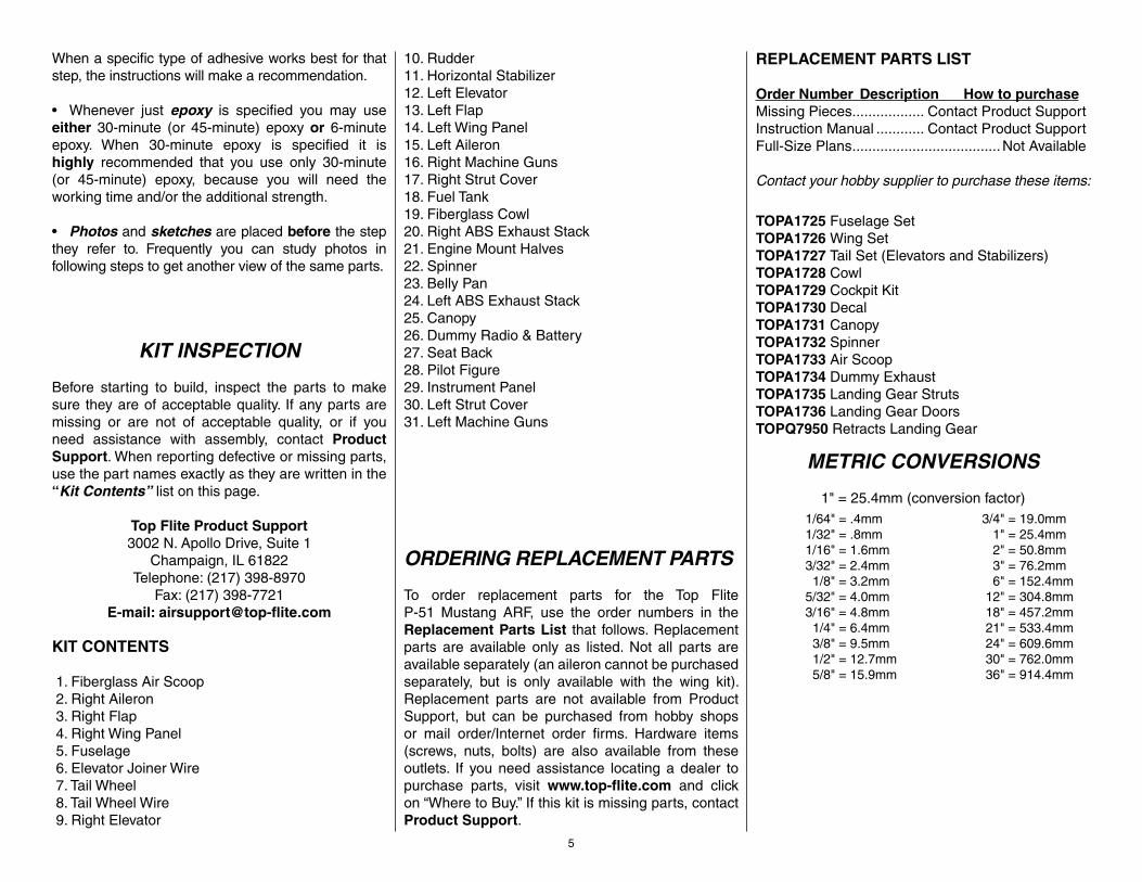
KIT INSPECTION
Before starting to build, inspect the parts to make sure they are of acceptable quality. If any parts are missing or are not of acceptable quality, or if you need assistance with assembly, contact Product Support. When reporting defective or missing parts, use the part names exactly as they are written in the “Kit Contents” list on this page.
Top Flite Product Support3002 N. Apollo Drive, Suite 1
Champaign, IL 61822Telephone: (217) 398-8970
Fax: (217) 398-7721E-mail: airsupport@top-fl ite.com
KIT CONTENTS
1. Fiberglass Air Scoop 2. Right Aileron 3. Right Flap 4. Right Wing Panel 5. Fuselage 6. Elevator Joiner Wire 7. Tail Wheel 8. Tail Wheel Wire 9. Right Elevator
10. Rudder11. Horizontal Stabilizer12. Left Elevator13. Left Flap14. Left Wing Panel15. Left Aileron16. Right Machine Guns17. Right Strut Cover18. Fuel Tank19. Fiberglass Cowl20. Right ABS Exhaust Stack21. Engine Mount Halves22. Spinner23. Belly Pan24. Left ABS Exhaust Stack25. Canopy26. Dummy Radio & Battery27. Seat Back28. Pilot Figure29. Instrument Panel30. Left Strut Cover31. Left Machine Guns
ORDERING REPLACEMENT PARTS
To order replacement parts for the Top Flite P-51 Mustang ARF, use the order numbers in the Replacement Parts List that follows. Replacement parts are available only as listed. Not all parts are available separately (an aileron cannot be purchased separately, but is only available with the wing kit). Replacement parts are not available from Product Support, but can be purchased from hobby shops or mail order/Internet order fi rms. Hardware items (screws, nuts, bolts) are also available from these outlets. If you need assistance locating a dealer to purchase parts, visit www.top-fl ite.com and click on “Where to Buy.” If this kit is missing parts, contact Product Support.
REPLACEMENT PARTS LIST
Order Number Description How to purchaseMissing Pieces .................. Contact Product SupportInstruction Manual ............ Contact Product SupportFull-Size Plans .....................................Not Available
Contact your hobby supplier to purchase these items:
TOPA1725 Fuselage SetTOPA1726 Wing SetTOPA1727 Tail Set (Elevators and Stabilizers)TOPA1728 CowlTOPA1729 Cockpit KitTOPA1730 DecalTOPA1731 CanopyTOPA1732 SpinnerTOPA1733 Air ScoopTOPA1734 Dummy ExhaustTOPA1735 Landing Gear StrutsTOPA1736 Landing Gear DoorsTOPQ7950 Retracts Landing Gear
METRIC CONVERSIONS
1" = 25.4mm (conversion factor) 1/64" = .4mm 1/32" = .8mm 1/16" = 1.6mm 3/32" = 2.4mm 1/8" = 3.2mm 5/32" = 4.0mm 3/16" = 4.8mm 1/4" = 6.4mm 3/8" = 9.5mm 1/2" = 12.7mm 5/8" = 15.9mm
3/4" = 19.0mm 1" = 25.4mm 2" = 50.8mm 3" = 76.2mm 6" = 152.4mm 12" = 304.8mm 18" = 457.2mm 21" = 533.4mm 24" = 609.6mm 30" = 762.0mm 36" = 914.4mm
5

2
4
1
517
20
18
16
19
24
23
26
28
29
27
30
15
31
13
11
10
12
7
6
14
6
3
9
8
22
2125

PREPARATIONS
❏ 1. If you have not done so already, remove the major parts of the kit from the box and inspect for damage. If any parts are damaged or missing, contact Product Support at the address or telephone number listed in the “Kit Inspection” section on page 5.
❏ 2. Carefully remove the tape and separate all the control surfaces. Use a covering iron with a covering sock on medium/high heat to tighten the covering if necessary. Apply pressure over sheeted areas to thoroughly bond the covering to the wood.
ASSEMBLE THE WING
HINGE THE AILERONS & FLAPS
You can do the right wing fi rst so your work matches the photos the fi rst time through, or you can work on them together.
❏ ❏ 1. Test fi t the included hinge points into the pre-drilled pockets in the fl ap. Press the hinge points into the pockets with the tabs on the hinge points aligned parallel with the hinge line on the fl ap. Push the hinge points as far deep as they can fi t into the pockets in the fl ap. Work the hinge up and down in the pocket. Be sure that the hinges move freely inside the pocket. If there is any interference, use a hobby knife to slightly enlarge the pocket as necessary.
❏ ❏ 2. Fit the fl ap to the wing panel by inserting the other ends of the hinge points into the pockets
in the wing TE. Push the fl ap up against the wing so that the fl ap LE and the wing TE edge touch. If the two surfaces cannot touch, carefully deepen the hinge point pockets in the wing panel with a 3/16" [4.8mm] drill bit as necessary. When satisfi ed, defl ect the fl ap down at least 1-1/4" [32mm] which will cause the pivot pins in the hinge points to align themselves in the center of the fl ap LE radius. Work the fl ap up and down to ensure smooth movement.
❏ ❏ 3. Remove the fl ap from the wing panel and pull the hinge points from the pockets. Coat the center of each hinge point with petroleum jelly or oil. This will prevent epoxy from sticking to the pivoting portion of the hinges.
Before performing steps 4 and 5, have denatured alcohol and some paper towel pieces ready for epoxy cleanup.
❏ ❏ 4. Mix up a batch of 30-minute epoxy. Use a toothpick or something similar to coat the insides of the hinge point pockets in the fl ap and the wing
7
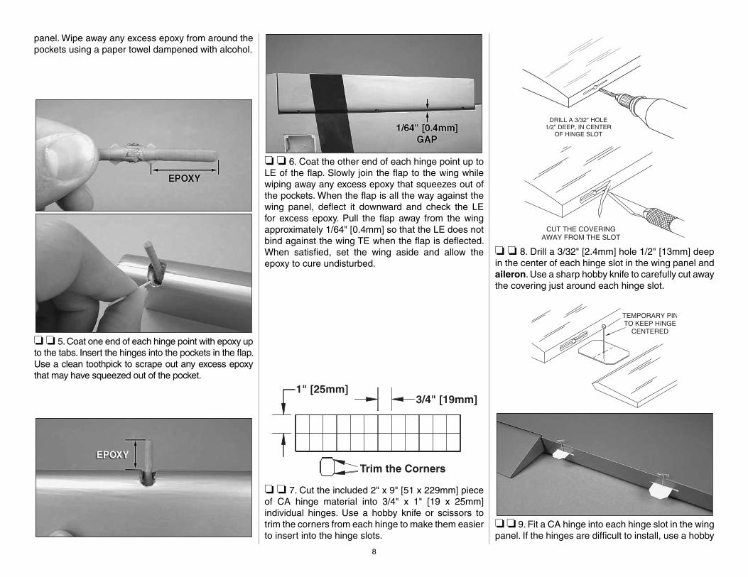
panel. Wipe away any excess epoxy from around the pockets using a paper towel dampened with alcohol.
❏ ❏ 5. Coat one end of each hinge point with epoxy up to the tabs. Insert the hinges into the pockets in the fl ap. Use a clean toothpick to scrape out any excess epoxy that may have squeezed out of the pocket.
❏ ❏ 6. Coat the other end of each hinge point up to LE of the fl ap. Slowly join the fl ap to the wing while wiping away any excess epoxy that squeezes out of the pockets. When the fl ap is all the way against the wing panel, defl ect it downward and check the LE for excess epoxy. Pull the fl ap away from the wing approximately 1/64" [0.4mm] so that the LE does not bind against the wing TE when the fl ap is defl ected. When satisfi ed, set the wing aside and allow the epoxy to cure undisturbed.
❏ ❏ 7. Cut the included 2" x 9" [51 x 229mm] piece of CA hinge material into 3/4" x 1" [19 x 25mm] individual hinges. Use a hobby knife or scissors to trim the corners from each hinge to make them easier to insert into the hinge slots.
❏ ❏ 8. Drill a 3/32" [2.4mm] hole 1/2" [13mm] deep in the center of each hinge slot in the wing panel and aileron. Use a sharp hobby knife to carefully cut away the covering just around each hinge slot.
❏ ❏ 9. Fit a CA hinge into each hinge slot in the wing panel. If the hinges are diffi cult to install, use a hobby
8
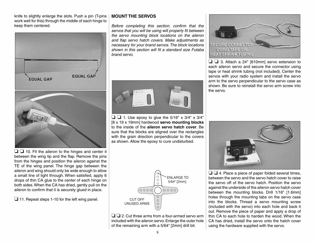
knife to slightly enlarge the slots. Push a pin (T-pins work well for this) through the middle of each hinge to keep them centered.
❏ ❏ 10. Fit the aileron to the hinges and center it between the wing tip and the fl ap. Remove the pins from the hinges and position the aileron against the TE of the wing panel. The hinge gap between the aileron and wing should only be wide enough to allow a small line of light through. When satisfi ed, apply 6 drops of thin CA glue to the center of each hinge on both sides. When the CA has dried, gently pull on the aileron to confi rm that it is securely glued in place.
❏ 11. Repeat steps 1-10 for the left wing panel.
MOUNT THE SERVOS
Before completing this section, confi rm that the servos that you will be using will properly fi t between the servo mounting block locations on the aileron and fl ap servo hatch covers. Make adjustments as necessary for your brand servos. The block locations shown in this section will fi t a standard size Futaba brand servo.
❏ ❏ 1. Use epoxy to glue the 5/16" x 3/4" x 3/4"[8 x 19 x 19mm] hardwood servo mounting blocks to the inside of the aileron servo hatch cover. Be sure that the blocks are aligned over the rectangles with the grain direction perpendicular to the covers as shown. Allow the epoxy to cure undisturbed.
❏ ❏ 2. Cut three arms from a four-armed servo arm included with the aileron servo. Enlarge the outer hole of the remaining arm with a 5/64" [2mm] drill bit.
❏ ❏ 3. Attach a 24" [610mm] servo extension to each aileron servo and secure the connector using tape or heat shrink tubing (not included). Center the servos with your radio system and install the servo arm to the servo perpendicular to the servo case as shown. Be sure to reinstall the servo arm screw into the servo.
❏ ❏ 4. Place a piece of paper folded several times, between the servo and the servo hatch cover to raise the servo off of the servo hatch. Position the servo against the underside of the aileron servo hatch cover between the mounting blocks. Drill 1/16" [1.6mm] holes through the mounting tabs on the servo case into the blocks. Thread a servo mounting screw (included with the servo) into each hole and back it out. Remove the piece of paper and apply a drop of thin CA to each hole to harden the wood. When the CA has dried, install the servo onto the hatch cover using the hardware supplied with the servo.
9

❏ ❏ 5. Use the string taped inside the aileron servo hatch to pull the servo lead through the wing ribs.
❏ ❏ 6. Thread a #2 x 3/8" [9.5mm] self-tapping screw into each hatch mounting hole and back it out. Apply a drop of thin CA to each hole to harden the wood. Install the aileron hatch cover to the wing as shown using four #2 x 3/8" [9.5mm] self-tapping screws.
❏ ❏ 7. Mount the fl ap servo and hatch cover in the same way. The fl ap servo does not require a servo lead extension.
❏ 8. Repeat steps 1 to 7 for the left wing panel. Make note that the fl ap servo arm will be mounted on the root rib side of the left wing panel so that when the fl ap servos are joined together using a Y-harness, they will both move in the same direction.
INSTALL THE AILERON & FLAP PUSHRODS
❏ ❏ 1. Thread a 2-56 nut and a metal clevis 15 complete turns onto a 4" [152mm] pushrod. Slide a silicone clevis retainer onto the clevis and connect the clevis to the outer hole of a nylon control horn.
❏ ❏ 2. Position the control horn over the plywood plate in the aileron (if you cannot see it, hold the aileron at a shallow angle in good lighting or use a small pin to puncture the covering) using the position of the servo arm as a guide. Align the holes in the control horn directly over the aileron hinge line and mark the location of the control horn mounting holes.
❏ ❏ 3. At the marks, drill 1/16" [1.6mm] holes through the plywood plate. Do not drill all the way through the aileron! Thread a #2 x 3/8" [9.5mm] self-tapping
10
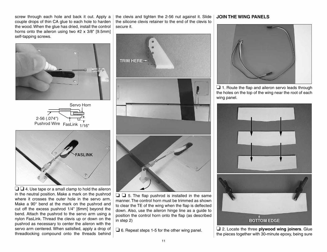
screw through each hole and back it out. Apply a couple drops of thin CA glue to each hole to harden the wood. When the glue has dried, install the control horns onto the aileron using two #2 x 3/8" [9.5mm] self-tapping screws.
❏ ❏ 4. Use tape or a small clamp to hold the aileron in the neutral position. Make a mark on the pushrod where it crosses the outer hole in the servo arm. Make a 90° bend at the mark on the pushrod and cut off the excess pushrod 1/4" [6mm] beyond the bend. Attach the pushrod to the servo arm using a nylon FasLink. Thread the clevis up or down on the pushrod as necessary to center the aileron with the servo arm centered. When satisfi ed, apply a drop of threadlocking compound onto the threads behind
the clevis and tighten the 2-56 nut against it. Slide the silicone clevis retainer to the end of the clevis to secure it.
❏ ❏ 5. The fl ap pushrod is installed in the same manner. The control horn must be trimmed as shown to clear the TE of the wing when the fl ap is defl ected down. Also, use the aileron hinge line as a guide to position the control horn onto the fl ap (as described in step 2)
❏ 6. Repeat steps 1-5 for the other wing panel.
JOIN THE WING PANELS
❏ 1. Route the fl ap and aileron servo leads through the holes on the top of the wing near the root of each wing panel.
❏ 2. Locate the three plywood wing joiners. Glue the pieces together with 30-minute epoxy, being sure
11

that the sides are fl ush with each other. Wipe away any excess epoxy with denatured alcohol. Small clamps can be used to hold the pieces together while the epoxy cures.
❏ 3. Test fi t the joiner into the wing joiner pocket of each wing panel with the “V” shaped side pointing to the bottom of the wing. The joiner should be able to fi t halfway into each pocket and be slightly loose to allow room for epoxy. Sand the joiner as necessary for the proper fi t. Dry fi t the wing panels together using the joiner and nylon anti-rotation pin. The root ribs of the panels should sit fl at against each other with no gaps. Lightly sand the face of the root ribs if necessary to eliminate any gaps between the wing panels.
❏ 4. When satisfi ed with the fi t of the wing panels, mix up a batch of 30-minute epoxy and coat the inside of the wing joiner pockets in each wing panel. Coat one half of the anti-rotation pin and press it into the hole at the TE edge of one wing panel. Coat one
half of the wing joiner and slide it into one wing panel. Coat the root ribs of both wing panels as well as the exposed ends of the joiner and anti-rotation pin. Join the two wing panels together and use paper towels dampened with denatured alcohol to wipe away any excess epoxy from the joint between the panels. Use masking tape to hold the panels together tightly. Set the wing aside and let the epoxy cure undisturbed.
❏ 5. Draw a line down the middle of the plywood wing bolt plate. Use a micro saw or a hobby knife to cut a groove down the line approximately halfway through the thickness of the plate. This groove will allow the plate to easily bend over the dihedral angle of the wing.
❏ 6. Position the wing bolt plate onto the underside of the wing with the bolt holes centered over the holes in the wing. Use a fi ne, felt-tip pen to trace along the outside of the plate onto the wing.
❏ 7. Remove the covering just inside the lines you drew. Glue the wing bolt plate into position.
How To Cut Covering From Balsa
Use a soldering iron to cut the covering from the area beneath the wing bolt plate. The tip of the soldering iron doesn’t have to be sharp, but a fi ne-tip does work best. Allow the iron to heat fully.
Use a straightedge to guide the soldering iron at a rate that will just melt the covering and not burn into the wood. The hotter the soldering iron, the faster it must travel to melt a fi ne cut. Peel off the covering.
12
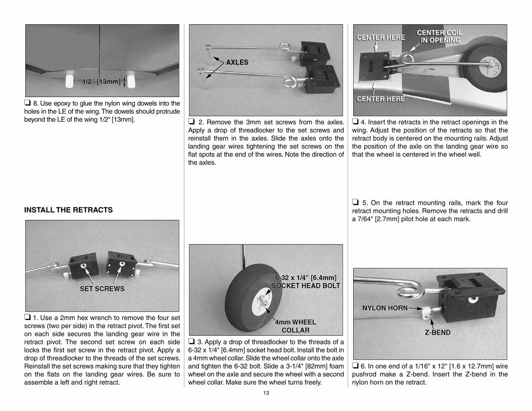
❏ 8. Use epoxy to glue the nylon wing dowels into the holes in the LE of the wing. The dowels should protrude beyond the LE of the wing 1/2" [13mm].
INSTALL THE RETRACTS
❏ 1. Use a 2mm hex wrench to remove the four set screws (two per side) in the retract pivot. The fi rst set on each side secures the landing gear wire in the retract pivot. The second set screw on each side locks the fi rst set screw in the retract pivot. Apply a drop of threadlocker to the threads of the set screws. Reinstall the set screws making sure that they tighten on the fl ats on the landing gear wires. Be sure to assemble a left and right retract.
❏ 2. Remove the 3mm set screws from the axles. Apply a drop of threadlocker to the set screws and reinstall them in the axles. Slide the axles onto the landing gear wires tightening the set screws on the fl at spots at the end of the wires. Note the direction of the axles.
❏ 3. Apply a drop of threadlocker to the threads of a 6-32 x 1/4" [6.4mm] socket head bolt. Install the bolt in a 4mm wheel collar. Slide the wheel collar onto the axle and tighten the 6-32 bolt. Slide a 3-1/4" [82mm] foam wheel on the axle and secure the wheel with a second wheel collar. Make sure the wheel turns freely.
❏ 4. Insert the retracts in the retract openings in the wing. Adjust the position of the retracts so that the retract body is centered on the mounting rails. Adjust the position of the axle on the landing gear wire so that the wheel is centered in the wheel well.
❏ 5. On the retract mounting rails, mark the four retract mounting holes. Remove the retracts and drill a 7/64" [2.7mm] pilot hole at each mark.
❏ 6. In one end of a 1/16" x 12" [1.6 x 12.7mm] wire pushrod make a Z-bend. Insert the Z-bend in the nylon horn on the retract.
13
❏ 7. Insert the retract wire in the retract pushrod tube. Position the retracts on the retract rails. Secure the retracts to the rails using four #6 x 1/2" [12.7mm] sheet metal screws. Operate the retracts by pushing and pulling the retract wire.
INSTALL THE RETRACT SERVO
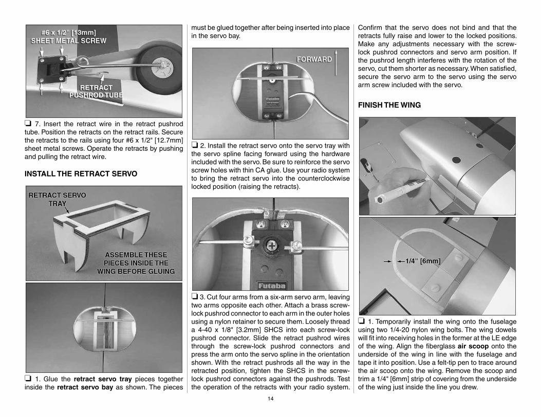
❏ 1. Glue the retract servo tray pieces together inside the retract servo bay as shown. The pieces
must be glued together after being inserted into place in the servo bay.
❏ 2. Install the retract servo onto the servo tray with the servo spline facing forward using the hardware included with the servo. Be sure to reinforce the servo screw holes with thin CA glue. Use your radio system to bring the retract servo into the counterclockwise locked position (raising the retracts).
❏ 3. Cut four arms from a six-arm servo arm, leaving two arms opposite each other. Attach a brass screw-lock pushrod connector to each arm in the outer holes using a nylon retainer to secure them. Loosely thread a 4-40 x 1/8" [3.2mm] SHCS into each screw-lock pushrod connector. Slide the retract pushrod wires through the screw-lock pushrod connectors and press the arm onto the servo spline in the orientation shown. With the retract pushrods all the way in the retracted position, tighten the SHCS in the screw-lock pushrod connectors against the pushrods. Test the operation of the retracts with your radio system.
Confi rm that the servo does not bind and that the retracts fully raise and lower to the locked positions. Make any adjustments necessary with the screw-lock pushrod connectors and servo arm position. If the pushrod length interferes with the rotation of the servo, cut them shorter as necessary. When satisfi ed, secure the servo arm to the servo using the servo arm screw included with the servo.
FINISH THE WING
❏ 1. Temporarily install the wing onto the fuselage using two 1/4-20 nylon wing bolts. The wing dowels will fi t into receiving holes in the former at the LE edge of the wing. Align the fi berglass air scoop onto the underside of the wing in line with the fuselage and tape it into position. Use a felt-tip pen to trace around the air scoop onto the wing. Remove the scoop and trim a 1/4" [6mm] strip of covering from the underside of the wing just inside the line you drew.
14

❏ 2. Sand the gluing edge of the air scoop with 220-grit sandpaper and clean the surface with alcohol. Place a piece of wax paper or plastic wrap between the wing and fuselage to prevent them from being glued together. Coat the gluing surface with epoxy and return the scoop to the wing. Use tape or a weight to hold the scoop in place while the epoxy cures. Clean up any excess epoxy with denatured alcohol.
❏ 3. Glue the belly pan to the front underside of the wing in the same manner as the air scoop.
❏ 4. Roughen the inside surface of the ABS machine guns with 220-grit sandpaper. Glue the machine guns to the wing LE 2-7/8" [73mm] from the outside edge of the white stripes.
OPTIONAL STRUT COVER INSTALLATION
Painted strut covers are provided for added realism and can be installed at the modeler’s discretion.
❏ 1. Position the strut covers over the landing gear struts aligning the colors on the covers with the covering on the wing. Center the covers in the openings. Use a felt-tip pen to mark the center of the landing gear strut onto each edge of the covers. Also, mark the position of the inside edge of the cover onto the strut. Accuracy in this step will ensure strut covers that are properly positioned onto the struts.
❏ 2. Lower the retracts and remove the wheels. Tape the strut covers to the struts using the marks you made as guides. Place two hump straps onto each strut in the positions shown and mark the location for the screw holes onto the undersides of the strut covers. Drill 3/32" [2.4mm] holes through the covers at the marks. Secure the covers to the
struts using eight 2-56 x 1/2" [13mm] machine screws and eight 2-56 nuts.
ASSEMBLE THE TAIL SECTION
INSTALL THE HORIZONTAL STABILIZER, ELEVATORS, SERVOS & LINKAGES
❏ 1. Cut three arms from a four-armed servo arm included with the elevator servo. Center the servo with your radio system and install the servo arm perpendicular to the servo case. Secure the servo arm with the servo arm screw. Place the servo onto the servo tray in the fuselage with the servo spline facing forward. Thread a 2-56 nut and a metal clevis onto a 36" [914mm] pushrod 15 complete turns. Insert the pushrod through the elevator pushrod tube and connect the clevis to the second hole from the center of the servo arm. With the elevator servo now positioned on the servo tray, use the screws that came with the servo to secure it in place. Be sure to harden the screw holes with thin CA.
15

❏ 2. Remove the pushrod and reinsert it from the aft end of the elevator pushrod tube through the horizontal stabilizer saddle. Place the elevator joiner rod into the half-circle notches at the aft end of
the stab saddle in the fuselage with the control horn pointing down toward the clevis. Slide the horizontal stab into the saddle in front of the joiner rod. Temporarily (without glue) join the elevator halves to the stab with CA hinges. The ends of the joiner rod fi t into the holes at the LE of each elevator half.
❏ 3. Use the access hole on the underside of the fuselage to connect the clevis to the outer hole of the elevator control horn. A medium-sized fl at blade screwdriver can be used to open the clevis and move it onto the control horn. Attach a metal solder clevis to the second hole from the center in the elevator servo arm. Use tape or small clamps to hold the elevators in the neutral position. Mark the elevator pushrod where it will need to be cut shorter to be soldered to the clevis. Before removing the elevators and stab from the fuselage, confi rm that both elevator TE are even with each other by looking at the plane from behind. If not, remove the elevators from the stab and bend or “tweak” the joiner rod until they do. Do not attempt to bend the joiner rod while it is installed in the elevators.
A A
B B
❏ 4. Temporarily install the wing onto the fuselage using two 1/4-20 nylon wing bolts. Center the stab left and right in the fuselage. Stand back 15 to 20ft [5 to 6m] and check to be sure the stab is parallel to the wing. If necessary, adjust the stab saddle as needed by lightly sanding it until the stab and wing are parallel. Measure the distance from the tip of each wing to the tip of the stab. Adjust the stab until the distance from the tip of the stab to the tip of the wing is equal on both sides. When satisfi ed with the
16
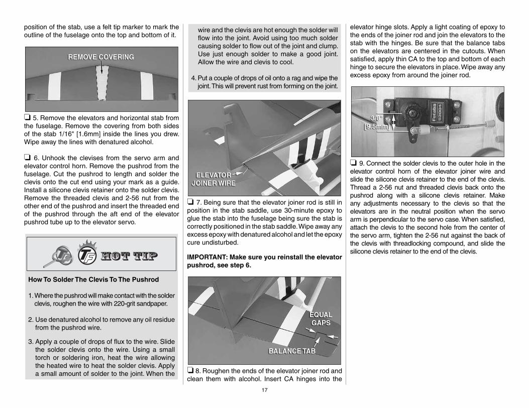
position of the stab, use a felt tip marker to mark the outline of the fuselage onto the top and bottom of it.
❏ 5. Remove the elevators and horizontal stab from the fuselage. Remove the covering from both sides of the stab 1/16" [1.6mm] inside the lines you drew. Wipe away the lines with denatured alcohol.
❏ 6. Unhook the clevises from the servo arm and elevator control horn. Remove the pushrod from the fuselage. Cut the pushrod to length and solder the clevis onto the cut end using your mark as a guide. Install a silicone clevis retainer onto the solder clevis. Remove the threaded clevis and 2-56 nut from the other end of the pushrod and insert the threaded end of the pushrod through the aft end of the elevator pushrod tube up to the elevator servo.
How To Solder The Clevis To The Pushrod
1. Where the pushrod will make contact with the solder clevis, roughen the wire with 220-grit sandpaper.
2. Use denatured alcohol to remove any oil residue from the pushrod wire.
3. Apply a couple of drops of fl ux to the wire. Slide the solder clevis onto the wire. Using a small torch or soldering iron, heat the wire allowing the heated wire to heat the solder clevis. Apply a small amount of solder to the joint. When the
wire and the clevis are hot enough the solder will fl ow into the joint. Avoid using too much solder causing solder to fl ow out of the joint and clump. Use just enough solder to make a good joint. Allow the wire and clevis to cool.
4. Put a couple of drops of oil onto a rag and wipe the joint. This will prevent rust from forming on the joint.
❏ 7. Being sure that the elevator joiner rod is still in position in the stab saddle, use 30-minute epoxy to glue the stab into the fuselage being sure the stab is correctly positioned in the stab saddle. Wipe away any excess epoxy with denatured alcohol and let the epoxycure undisturbed.
IMPORTANT: Make sure you reinstall the elevator pushrod, see step 6.
❏ 8. Roughen the ends of the elevator joiner rod and clean them with alcohol. Insert CA hinges into the
elevator hinge slots. Apply a light coating of epoxy to the ends of the joiner rod and join the elevators to the stab with the hinges. Be sure that the balance tabs on the elevators are centered in the cutouts. When satisfi ed, apply thin CA to the top and bottom of each hinge to secure the elevators in place. Wipe away any excess epoxy from around the joiner rod.
❏ 9. Connect the solder clevis to the outer hole in the elevator control horn of the elevator joiner wire and slide the silicone clevis retainer to the end of the clevis. Thread a 2-56 nut and threaded clevis back onto the pushrod along with a silicone clevis retainer. Make any adjustments necessary to the clevis so that the elevators are in the neutral position when the servo arm is perpendicular to the servo case. When satisfi ed, attach the clevis to the second hole from the center of the servo arm, tighten the 2-56 nut against the back of the clevis with threadlocking compound, and slide the silicone clevis retainer to the end of the clevis.
17
18
INSTALL THE RUDDER, TAIL WHEEL& LINKAGES
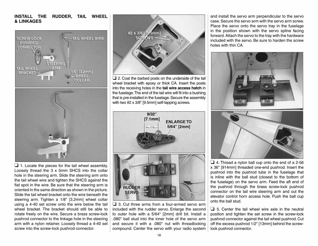
❏ 1. Locate the pieces for the tail wheel assembly. Loosely thread the 3 x 5mm SHCS into the collar hole in the steering arm. Slide the steering arm onto the tail wheel wire and tighten the SHCS against the fl at spot in the wire. Be sure that the steering arm is oriented in the same direction as shown in the picture. Slide the tail wheel bracket onto the wire beneath the steering arm. Tighten a 1/8" [3.2mm] wheel collar using a 4-40 set screw onto the wire below the tail wheel bracket. The bracket should still be able to rotate freely on the wire. Secure a brass screw-lock pushrod connector to the linkage hole in the steering arm with a nylon retainer. Loosely thread a 4-40 set screw into the screw-lock pushrod connector.
❏ 2. Coat the barbed posts on the underside of the tail wheel bracket with epoxy or thick CA. Insert the posts into the receiving holes in the tail wire access hatch in the fuselage. The end of the tail wire will fi t into a bushing that is pre-installed in the fuselage. Secure the assembly with two #2 x 3/8" [9.5mm] self-tapping screws.
❏ 3. Cut three arms from a four-armed servo arm included with the rudder servo. Enlarge the second to outer hole with a 5/64" [2mm] drill bit. Install a .080" ball stud into the inner hole of the servo arm and secure it with a .080" nut with threadlocking compound. Center the servo with your radio system
and install the servo arm perpendicular to the servo case. Secure the servo arm with the servo arm screw. Place the servo onto the servo tray in the fuselage in the position shown with the servo spline facing forward. Attach the servo to the tray with the hardware included with the servo. Be sure to harden the screw holes with thin CA.
❏ 4. Thread a nylon ball cup onto the end of a 2-56 x 36" [914mm] threaded one-end pushrod. Insert the pushrod into the pushrod tube in the fuselage that is inline with the ball stud (closest to the bottom of the fuselage) on the servo arm. Feed the aft end of the pushrod through the brass screw-lock pushrod connector on the tail wire steering arm and out the elevator control horn access hole. Push the ball cup onto the ball stud.
❏ 5. Center the tail wheel wire axle in the neutral position and tighten the set screw in the screw-lock pushrod connector against the tail wheel pushrod. Cut off the excess pushrod 1/2" [13mm] behind the screw-lock pushrod connector.
19
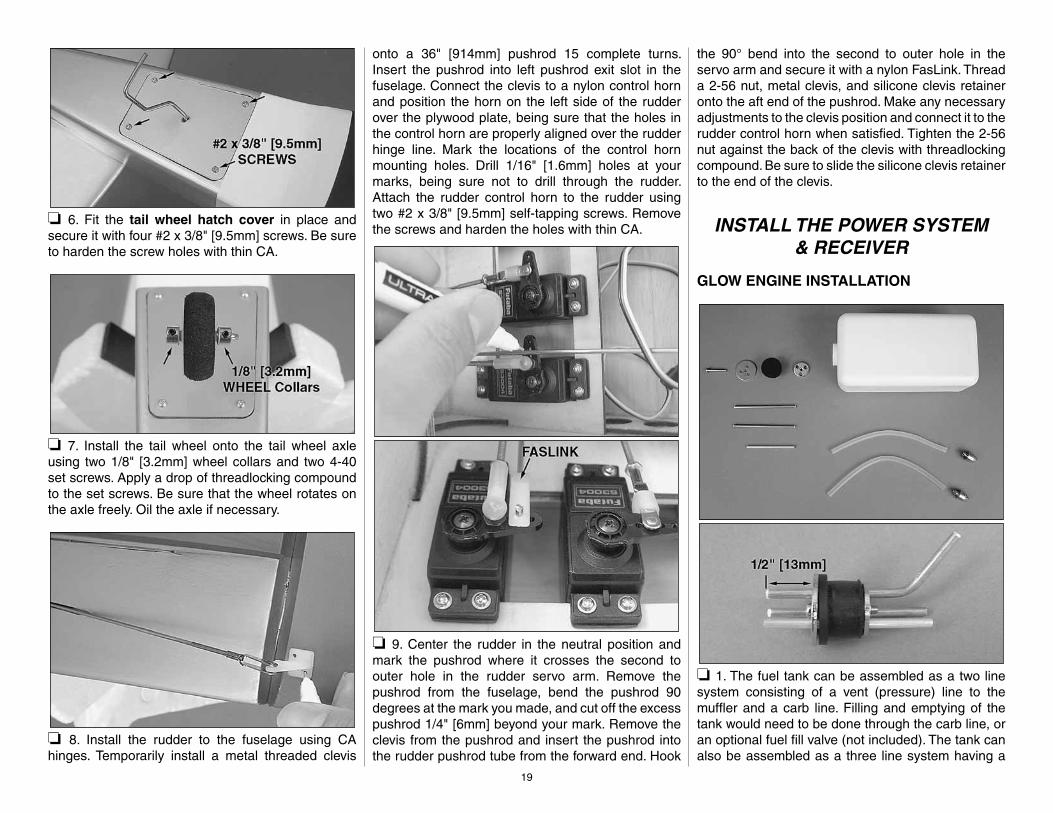
❏ 6. Fit the tail wheel hatch cover in place and secure it with four #2 x 3/8" [9.5mm] screws. Be sure to harden the screw holes with thin CA.
❏ 7. Install the tail wheel onto the tail wheel axle using two 1/8" [3.2mm] wheel collars and two 4-40 set screws. Apply a drop of threadlocking compound to the set screws. Be sure that the wheel rotates on the axle freely. Oil the axle if necessary.
❏ 8. Install the rudder to the fuselage using CA hinges. Temporarily install a metal threaded clevis
onto a 36" [914mm] pushrod 15 complete turns. Insert the pushrod into left pushrod exit slot in the fuselage. Connect the clevis to a nylon control horn and position the horn on the left side of the rudder over the plywood plate, being sure that the holes in the control horn are properly aligned over the rudder hinge line. Mark the locations of the control horn mounting holes. Drill 1/16" [1.6mm] holes at your marks, being sure not to drill through the rudder. Attach the rudder control horn to the rudder using two #2 x 3/8" [9.5mm] self-tapping screws. Remove the screws and harden the holes with thin CA.
❏ 9. Center the rudder in the neutral position and mark the pushrod where it crosses the second to outer hole in the rudder servo arm. Remove the pushrod from the fuselage, bend the pushrod 90 degrees at the mark you made, and cut off the excess pushrod 1/4" [6mm] beyond your mark. Remove the clevis from the pushrod and insert the pushrod into the rudder pushrod tube from the forward end. Hook
the 90° bend into the second to outer hole in the servo arm and secure it with a nylon FasLink. Thread a 2-56 nut, metal clevis, and silicone clevis retainer onto the aft end of the pushrod. Make any necessary adjustments to the clevis position and connect it to the rudder control horn when satisfi ed. Tighten the 2-56 nut against the back of the clevis with threadlocking compound. Be sure to slide the silicone clevis retainer to the end of the clevis.
INSTALL THE POWER SYSTEM& RECEIVER
GLOW ENGINE INSTALLATION
❏ 1. The fuel tank can be assembled as a two line system consisting of a vent (pressure) line to the muffl er and a carb line. Filling and emptying of the tank would need to be done through the carb line, or an optional fuel fi ll valve (not included). The tank can also be assembled as a three line system having a

20
vent line, carb line, and fi ll line. If installing a fi ll line, puncture the top of the stopper above the sealed off fuel tube hole. The fi ll and carb lines should extend out 1/2" [13mm] beyond the stopper and the vent line should be bent upwards and left uncut. With the tubes installed in the stopper, fi t the stopper plates loosely in place with the 3 x 25mm Phillips screw to hold the assembly together.
❏ 2. Fit the stopper assembly into the tank with the vent line pointing toward the top of the tank, but not touching. The fuel tubing and clunks (fuel pickup) on the carb and fi ll lines should almost reach the back of the tank but not touch. The clunks must be able to move freely inside the tank when assembled. Adjust the length of the fuel tubing accordingly. When satisfi ed, tighten the 3 x 25mm screw in the stopper to secure it in place (do not overtighten). Mark the side of the tank that must face up when installed in the plane, and we also suggest marking the tubes in the stopper.
❏ 3. Insert the tank into the fuselage with the correct side facing up. The neck of the tank should pass through the hole in the fi rewall. Attach a 6" to 7" [152 to 178mm] piece of fuel tubing onto each line coming from the tank.
❏ 4. Using four 8-32 x 1" [25mm] SHCS, four #8 fl at washers, four #8 lock washers, and threadlocking compound, attach the engine mount inverted to the fi rewall. Leave the screws slightly loose. Test fi t your engine between the mount halves. Align the centering
mark on the engine mount with the lines on the fi rewall. Slide the mount halves against the sides of the engine and fi nish tightening the mount screws.
❏ 5. Position the front of the engine drive washer 6-1/8" [156mm] from the fi rewall. Mark the location of the engine mount holes onto the mount rails using a Dead Center hole locator. Remove the engine from the mount and use a 8-32 tap and drill set to create

21
threads in the four mounting holes. Attach the engine to the mount using four 8-32 x 1" [25mm] SHCS, four #8 fl at washers, and four #8 lock washers.
❏ 6. Glue the throttle servo tray in the location shown. Be sure that the cutout for the throttle servo is on the same side of the plane as the throttle arm on the carburetor.
❏ 7. Cut three arms from a four-armed servo arm. Install a brass screw-lock pushrod connector into the second hole from the center of the remaining arm using a nylon retainer. Loosely thread a 4-40 x 1/8" [3mm] SHCS into the screw-lock pushrod connector. Install the throttle servo into the throttle servo tray with the servo splines toward the rear of the plane. Use your radio system to center the servo and attach the arm perpendicular to the servo case pointing away from the center of the fuselage. Be sure to install the servo arm screw.
❏ 8. Make the necessary bends in the remaining 36" [914mm] pushrod so that it will connect to the throttle arm on your carburetor using a nylon clevis and silicone clevis retainer. If installing the O.S. FS-91 Surpass II four-stroke engine, a “U” bend will need to be made in the pushrod to reach the throttle arm. Be sure that the bends you make are not in the threaded portion of the rod. Some of the threads on the pushrod can be cut off to get the clevis closer to the “U” bend. Fit the aft end of the pushrod through the screw-lock pushrod connector in the throttle servo arm. Make any necessary adjustments to the pushrod position and tighten the screw in the screw-lock pushrod connector when satisfi ed. Cut off the excess pushrod 1/4" [6mm] beyond the screw-lock pushrod connector.
❏ 9. Test the operation of the throttle servo with your radio system, making sure that the servo can properly open and close the carburetor.
INSTALL THE RECEIVER & BATTERY
❏ 1. Glue the fuel tank brace to the receiver tray in the direction shown.
❏ 2. Make two hook and loop straps by overlapping the mating ends by approximately 1" [25mm]. Cut two pieces of foam rubber (not included) to match your receiver and receiver battery pack. Secure the receiver and receiver pack to the receiver tray with the straps and cut them to the necessary length. Feed the antenna and battery lead beneath the air tank tray and secure the radio tray to the fuselage

22
using four #2 x 3/8" [9.5mm] self-tapping screws and four #2 fl at washers. Be sure to harden the screw holes with thin CA.
❏ 3. Install your receiver switch onto the side of the fuselage opposite the muffl er and in a location that will not interfere with any of the servos. We used a Great Planes Switch and Charge Jack Mounting Set (GPMM1000). Connect your servos and switch to the receiver and connect the receiver battery to the switch. Be sure to use tape or heat shrink tubing to secure the connection between the switch and the battery.
❏ 4. Install a strain-relief onto the receiver antenna and route it through the antenna tube and out the
back of the fuselage. We used a small piece of fuel tubing glued to the side of the fuselage to hold the antenna out of the way of the elevator servo.
FINISH THE MODEL
INSTALL THE COWL
❏ 1. If you haven’t done so already, connect the fuel pickup line to the needle valve on the engine and cut the fi ll line and pressure line to the proper length. An aluminum fuel line plug is provided for the fi ll line.
❏ 2. Make the necessary cutouts in the cowl to match your engine. In the picture, there is an opening for the engine head, muffl er, cooling hole, and needle valve.
❏ 3. Use a felt-tip pen to mark the middle of each cowl mounting block just outside the cowl line onthe fuselage.
❏ 4. Tape the cowl into position with masking tape. Transfer the marks you made in step 3 onto the cowl 1/4" [6mm] inside the cowl edges.
❏ 5. Drill through the marks on the cowl with a 1/16" [1.6mm] drill bit. Remove the cowl and enlarge the holes in the cowl with a 3/32" [2.4mm] bit. Thread a #2 x 3/8" [9.5mm] self-tapping screw into each cowl mounting block and remove it. Apply a couple drops of
23
thin CA into each hole to harden the wood. Position the cowl onto the fuselage and shift it to one side in order to install the muffl er onto the header pipe. Install the cowl onto the fuselage using seven #2 x 3/8" [9.5mm] self-tapping screws and seven #2 fl at washers.
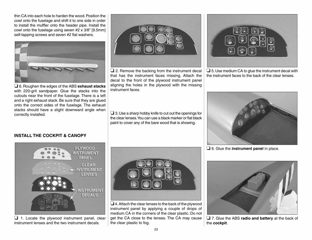
❏ 6. Roughen the edges of the ABS exhaust stacks with 220-grit sandpaper. Glue the stacks into the cutouts near the front of the fuselage. There is a left and a right exhaust stack. Be sure that they are glued onto the correct sides of the fuselage. The exhaust stacks should have a slight downward angle when correctly installed.
INSTALL THE COCKPIT & CANOPY
❏ 1. Locate the plywood instrument panel, clear instrument lenses and the two instrument decals.
❏ 2. Remove the backing from the instrument decal that has the instrument faces missing. Attach the decal to the front of the plywood instrument panel aligning the holes in the plywood with the missing instrument faces.
❏ 3. Use a sharp hobby knife to cut out the openings for the clear lenses. You can use a black marker or fl at black paint to cover any of the bare wood that is showing.
❏ 4. Attach the clear lenses to the back of the plywood instrument panel by applying a couple of drops of medium CA in the corners of the clear plastic. Do not get the CA close to the lenses. The CA may cause the clear plastic to fog.
❏ 5. Use medium CA to glue the instrument decal with the instrument faces to the back of the clear lenses.
❏ 6. Glue the instrument panel in place.
❏ 7. Glue the ABS radio and battery at the back of the cockpit.

24
❏ 8. Glue the pilot fi gure and seat back to the cockpit fl oor. For ease of installation, we recommend gluing the seat back to the pilot before installing them into position.
Pilot Figure Base
To provide a larger surface for gluing, install a plywood base inside the pilot fi gure. To do this, trace the outline of the base of the pilot onto a piece of paper. Sketch another line 1/8" [3mm] inside the traced line. Tape the paper to a scrap piece of plywood (not included) and cut out the piece along the inside line you drew. Test fi t the piece into the base of the pilot and sand as necessary. Roughen the inside of the pilot fi gure near the base using
a rotary tool such as a Dremel with a sanding bit or some 220-grit sandpaper. Glue the plywood piece into the base with a mixture of epoxy and Microballoons. When the epoxy has cured, sand away any excess epoxy for a smooth, fl at base. A screw can be installed through the cockpit fl oor and into the plywood piece for extra security after the pilot fi gure has been glued into the cockpit.
❏ 9. Glue the canopy to the fuselage using canopy glue such as J&Z R/C 56 Canopy Glue (JOZR5007).
INSTALL THE PROPELLER & SPINNER
❏ 1. The spinner backplate is drilled to fi t a 3/8" [9.5mm] crankshaft. A brass insert is also included for 5/16" [7.9mm] crankshafts. Fit the spinner backplate onto the crankshaft. A fl at bottomed spinner nut is provided for use with a two-stroke engine, and a spinner nut is also provided for use with the O.S. .91 four-stroke engine. Install the propeller and prop washer onto the crankshaft and tighten it down with the appropriate spinner nut.
❏ 2. The 4mm spinner bolt may need to be cut shorter depending on your choice of engine installation. Test fi t the spinner cone onto the backplate and determine how short the spinner bolt will be. Thread one of the spinner nuts onto the bolt before cutting it shorter in order to straighten any damaged threads that may occur from the cutting process. When satisfi ed, double check the tightness of the spinner nut, and install the spinner cone onto the backplate using the 4mm spinner bolt.

25
❏ 3. This completes the assembly process!
OPTIONAL PNEUMATIC RETRACTS
Mounting locations are provided in the fuselage for optional pneumatic retract hardware including the air vessel, air valve, and air valve servo. Tabs are designed into the former at the front of the air tank for securing it with rubber bands. Cutout the opening for
a Robart small air tank along the perforations in the air tank tray. Detailed installation instructions are not provided for installing pneumatic retracts, however the installation process for the gear is similar to the mechanical installation. The mechanical retract pushrods will need to be replaced with air lines. Be sure to follow the instructions included with the pneumatic retract kit.
APPLY THE DECALS
❏ 1. Use scissors or a sharp hobby knife to cut the decals from the sheet.
❏ 2. Be certain the model is clean and free from oily fi ngerprints and dust. Prepare a dishpan or small bucket with a mixture of liquid dish soap and warm water–about one teaspoon of soap per gallon of water. Submerse the decal in the soap and water and peel off the paper backing. Note: Even though the decals have a “sticky-back” and are not the water transfer type, submersing them in soap & water allows accurate positioning and reduces air bubbles underneath.
❏ 3. Position a decal on the model where desired. Holding the decal down, use a paper towel to wipe most of the water away.
❏ 4. Use a piece of soft balsa wrapped in a paper towel or something similar to squeegee remaining water from under the decal. Apply the rest of the decals the same way.
GET THE MODEL READY TO FLY
CHECK THE CONTROL DIRECTIONS
❏ 1. Turn on the transmitter and receiver and center the trims. If necessary, remove the servo arms from the servos and reposition them so they are centered. Reinstall the screws that hold on the servo arms.
❏ 2. With the transmitter and receiver still on, check all the control surfaces to see if they are centered. If necessary, adjust the clevises on the pushrods to center the control surfaces.
FULL THROTTLERUDDER MOVES RIGHT
ELEVATOR MOVES UP RIGHT AILERON MOVES UPLEFT AILERON MOVES DOWN
4-CHANNEL RADIO SETUP(STANDARD MODE 2)
❏ 3. Make certain that the control surfaces and the carburetor respond in the correct direction as shown in the diagram. If any of the controls respond in the wrong direction, use the servo reversing in the transmitter to reverse the servos connected to those controls. Be certain the control surfaces have remained centered. Adjust if necessary.

26
SET THE CONTROL THROWS
Use a Great Planes AccuThrow (or a ruler) to accurately measure and set the control throw of each control surface as indicated in the chart that follows. If your radio does not have dual rates, we recommend setting the throws at the low rate setting.
Note: The throws are measured at the widest part of the elevators, rudder and ailerons.
These are the recommended control surface throws:
High Rate Low RateELEVATOR: 5/8" [16mm] up 3/8" [9.5mm] up 5/8" [16mm] down 3/8" [9.5mm] down
RUDDER: 1-1/8" [29mm] right 7/8" [22mm] right 1-1/8" [29mm] left 7/8" [22mm] left
AILERONS: 11/16" [17.5mm] up 1/2" [13mm] up 11/16" [17.5mm] down 1/2" [13mm] down
FLAPS: 1-1/4" [32mm] down 5/8" [16mm] down (full fl ap) (1/2 fl ap)
IMPORTANT: The P-51 Mustang ARF has been extensively fl own and tested to arrive at the throws at which it fl ies best. Flying your model at these throws will provide you with the greatest chance for successful fi rst fl ights. If, after you have become accustomed to the way the P-51 fl ies, you would like to change the throws to suit your taste, that is fi ne. However, too much control throw could make the model diffi cult to control, so remember, “more is not always better.”
FLIGHT NOTE: The high rate elevator is more than enough throw for normal fl ight. However, the extra throw helps keep the nose up when taking off from rough grass. Once the plane is in the air, the low rate elevator is recommended. Also, 20% to 30% exponential can be put in the high rate elevator to reduce the sensitivity.
BALANCE THE MODEL (C.G.)
More than any other factor, the C.G. (balance point) can have the greatest effect on how a model fl ies, and may determine whether or not your fi rst fl ight will be successful. If you value this model and wish to enjoy it for many fl ights, DO NOT OVERLOOK THIS IMPORTANT PROCEDURE. A model that is not properly balanced will be unstable and possibly unfl yable.
At this stage the model should be in ready-to-fl y condition with all of the systems in place including the engine, landing gear, and the radio system.
❏ 1. Use a felt-tip pen or 1/8" [3mm]-wide tape to accurately mark the C.G. on the top of the wing on both sides of the fuselage. The C.G. is located 5-5/8" [143mm] back from the LE of the wing where it meets the fuselage sides.
This is where your model should balance for the fi rst fl ights. Later, you may wish to experiment by shifting the C.G. up to 1/4" [6mm] forward or 1/4" [6mm] back to change the fl ying characteristics. Moving the C.G. forward may improve the smoothness and stability, but the model may then require more speed for takeoff and make it more diffi cult to slow for landing. Moving the C.G. aft makes the model more maneuverable, but could also cause it to become too diffi cult to control. In any case, start at the recommended balance point and do not at any time balance the model outside the specifi ed range.
❏ 2. With the wing attached to the fuselage, all parts of the model installed (ready to fl y) and an empty fuel tank, place the model upside-down on a Great Planes C.G. Machine, or lift it upside-down at the balance point you marked.
❏ 3. If the tail drops, the model is “tail heavy” and the battery pack and/or receiver must be shifted forward or weight must be added to the nose to balance. If the nose drops, the model is “nose heavy” and the battery pack and/or receiver must be shifted aft or weight must be added to the tail to balance. If possible, relocate the battery pack and receiver to minimize or eliminate any additional ballast required. If additional weight is required, nose weight may be easily added by using a “spinner weight” (GPMQ4645 for the 1 oz. [28g] weight, or GPMQ4646 for the 2 oz. [57g] weight). If spinner weight is not practical or is not enough, use Great
27
Planes (GPMQ4485) “stick-on” lead. A good place to add stick-on nose weight is to the fi rewall (don’t attach weight to the cowl–it is not intended to support weight). Begin by placing incrementally increasing amounts of weight on the bottom of the fuselage over the fi rewall until the model balances. Once you have determined the amount of weight required, it can be permanently attached. If required, tail weight may be added by cutting open the bottom of the fuselage and gluing it permanently inside.
Note: Do not rely upon the adhesive on the back of the lead weight to permanently hold it in place. Over time, fuel and exhaust residue may soften the adhesive and cause the weight to fall off. Use #2 sheet metal screws, RTV silicone or epoxy to permanently hold the weight in place.
❏ 4. IMPORTANT: If you found it necessary to add any weight, recheck the C.G. after the weight has been installed.
BALANCE THE MODEL LATERALLY
❏ 1. With the wing level, have an assistant help you lift the model by the engine propeller shaft and the bottom of the fuselage under the TE of the fi n. Do this several times.
❏ 2. If one wing always drops when you lift the model, it means that side is heavy. Balance the airplane by adding weight to the other wing tip. An airplane that has been laterally balanced will track better in loops and other maneuvers.
PREFLIGHT
IDENTIFY YOUR MODEL
No matter if you fl y at an AMA sanctioned R/C club site or if you fl y somewhere on your own, you should always have your name, address, telephone number and AMA number on or inside your model. It is required at all AMA R/C club fl ying sites and AMA
sanctioned fl ying events. Fill out the identifi cation tag on page 29 (or on the decal sheet) and place it on or inside your model.
CHARGE THE BATTERIES
Follow the battery charging instructions that came with your radio control system to charge the batteries. You should always charge your transmitter and receiver batteries the night before you go fl ying, and at other times as recommended by the radio manufacturer.
CAUTION: Unless the instructions that came with your radio system state differently, the initial charge on new transmitter and receiver batteries should be done for 15 hours using the slow-charger that came with the radio system. This will “condition” the batteries so that the next charge may be done using the fast-charger of your choice. If the initial charge is done with a fast-charger the batteries may not reach their full capacity and you may be fl ying with batteries that are only partially charged.
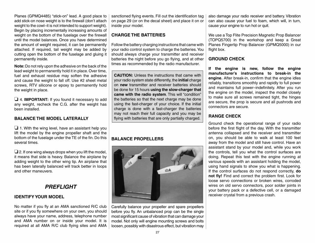
BALANCE PROPELLERS
Carefully balance your propeller and spare propellers before you fl y. An unbalanced prop can be the single most signifi cant cause of vibration that can damage your model. Not only will engine mounting screws and bolts loosen, possibly with disastrous effect, but vibration may
also damage your radio receiver and battery. Vibration can also cause your fuel to foam, which will, in turn, cause your engine to run hot or quit.
We use a Top Flite Precision Magnetic Prop Balancer (TOPQ5700) in the workshop and keep a Great Planes Fingertip Prop Balancer (GPMQ5000) in our fl ight box.
GROUND CHECK
If the engine is new, follow the engine manufacturer’s instructions to break-in the engine. After break-in, confi rm that the engine idles reliably, transitions smoothly and rapidly to full power and maintains full power–indefi nitely. After you run the engine on the model, inspect the model closely to make sure all screws remained tight, the hinges are secure, the prop is secure and all pushrods and connectors are secure.
RANGE CHECK
Ground check the operational range of your radio before the fi rst fl ight of the day. With the transmitter antenna collapsed and the receiver and transmitter on, you should be able to walk at least 100 feet away from the model and still have control. Have an assistant stand by your model and, while you work the controls, tell you what the control surfaces are doing. Repeat this test with the engine running at various speeds with an assistant holding the model, using hand signals to show you what is happening. If the control surfaces do not respond correctly, do not fl y! Find and correct the problem fi rst. Look for loose servo connections or broken wires, corroded wires on old servo connectors, poor solder joints in your battery pack or a defective cell, or a damaged receiver crystal from a previous crash.

28
ENGINE SAFETY PRECAUTIONS
Failure to follow these safety precautions may result in severe injury to yourself and others.
Keep all engine fuel in a safe place, away from high heat, sparks or fl ames, as fuel is very fl ammable. Do not smoke near the engine or fuel; and remember that engine exhaust gives off a great deal of deadly carbon monoxide. Therefore, do not run the engine in a closed room or garage.
Get help from an experienced pilot when learning to operate engines.
Use safety glasses when starting or running engines.
Do not run the engine in an area of loose gravel or sand; the propeller may throw such material in your face or eyes.
Keep your face and body as well as all spectators away from the plane of rotation of the propeller as you start and run the engine.
Keep these items away from the prop: loose clothing, shirt sleeves, ties, scarfs, long hair or loose objects such as pencils or screwdrivers that may fall out of shirt or jacket pockets into the prop.
Use a “chicken stick” or electric starter to start the engine. Do not use your fi ngers to fl ip the propeller. Make certain the glow plug clip or connector is secure so that it will not pop off or otherwise get into the running propeller.
Make all engine adjustments from behind therotating propeller.
The engine gets hot! Do not touch it during or right after operation. Make sure fuel lines are in good condition so fuel will not leak onto a hot engine, causing a fi re.
To stop a glow engine, cut off the fuel supply by closing off the fuel line or following the engine manufacturer’s
recommendations. Do not use hands, fi ngers or any other body part to try to stop the engine. To stop a gasoline powered engine, an on/off switch should be connected to the engine coil. Do not throw anything into the propeller of a running engine.
AMA SAFETY CODE (EXCERPTS)
Read and abide by the following excerpts from the Academy of Model Aeronautics Safety Code. For the complete Safety Code refer to Model Aviation magazine, the AMA web site or the Code that came with your AMA license.
GENERAL
1) I will not fl y my model aircraft in sanctioned events, air shows, or model fl ying demonstrations until it has been proven to be airworthy by having been previously, successfully fl ight tested.
2) I will not fl y my model aircraft higher than approximately 400 feet within 3 miles of an airport without notifying the airport operator. I will give right-of-way and avoid fl ying in the proximity of full-scale aircraft. Where necessary, an observer shall be utilized to supervise fl ying to avoid having models fl y in the proximity of full-scale aircraft.
3) Where established, I will abide by the safety rules for the fl ying site I use, and I will not willfully and deliberately fl y my models in a careless, reckless and/or dangerous manner.
5) I will not fl y my model unless it is identifi ed with my name and address or AMA number, on or in the model. Note: This does not apply to models while being fl own indoors.
7) I will not operate models with pyrotechnics (any device that explodes, burns, or propels a projectile of any kind).
RADIO CONTROL
1) I will have completed a successful radio equipment ground check before the fi rst fl ight of a new orrepaired model.
2) I will not fl y my model aircraft in the presence of spectators until I become a qualifi ed fl ier, unless assisted by an experienced helper.3) At all fl ying sites a straight or curved line(s) must be established in front of which all fl ying takes place with the other side for spectators. Only personnel involved with fl ying the aircraft are allowed at or in the front of the fl ight line. Intentional fl ying behind the fl ight line is prohibited.
4) I will operate my model using only radio control frequencies currently allowed by the Federal Communications Commission.
5) I will not knowingly operate my model within three miles of any pre-existing fl ying site except in accordance with the frequency sharing agreement listed (in the complete AMA Safety Code).
9) Under no circumstances may a pilot or other person touch a powered model in fl ight; nor should any part of the model other than the landing gear, intentionally touch the ground, except while landing.
29
CHECK LIST
During the last few moments of preparation your mind may be elsewhere anticipating the excitement of the fi rst fl ight. Because of this, you may be more likely to overlook certain checks and procedures that should be performed before the model is fl own. To help avoid this, a check list is provided to make sure these important areas are not overlooked. Many are covered in the instruction manual, so where appropriate, refer to the manual for complete instructions. Be sure to check the items off as they are completed.
❏ 1. Fuelproof all areas exposed to fuel or exhaust residue such as the cowl mounting blocks, wing saddle area, etc.
❏ 2. Check the C.G. according to the measurements provided in the manual.
❏ 3. Be certain the battery and receiver are securely mounted in the fuselage. Simply stuffi ng them into place with foam rubber is not suffi cient.
❏ 4. Extend your receiver antenna and make sure it has a strain relief inside the fuselage to keep tension off the solder joint inside the receiver.
❏ 5. Balance your model laterally as explained in the instructions.
❏ 6. Use threadlocking compound to secure critical fasteners such as the set screws that hold the wheel axles to the struts, screws that hold the carburetor arm (if applicable), screw-lock pushrod connectors, etc.
❏ 7. Add a drop of oil to the axles so the wheels will turn freely.
❏ 8. Make sure all hinges are securely glued in place.❏ 9. Reinforce holes for wood screws with thin CA
where appropriate (servo mounting screws, cowl mounting screws, etc.).
❏ 10. Confi rm that all controls operate in the correct direction and the throws are set up according to the manual.
❏ 11. Make sure there are silicone retainers on all the clevises and that all servo arms are secured to the servos with the screws included withyour radio.
❏ 12. Secure connections between servo wires and Y-connectors or servo extensions, and the connection between your battery pack and the on/off switch with vinyl tape, heat shrink tubing or special clips suitable for that purpose.
❏ 13. Make sure any servo extension cords you may have used do not interfere with other systems (servo arms, pushrods, etc.).
❏ 14. Secure the pressure tap (if used) to the muffl er with high temp RTV silicone, threadlocking compound or J.B. Weld.
❏ 15. Make sure the fuel lines are connected and are not kinked.
❏ 16. Use an incidence meter to check the wing for twists and attempt to correct before fl ying.
❏ 17. Balance your propeller (and spare propellers).❏ 18. Tighten the propeller nut and spinner.❏ 19. Place your name, address, AMA number and
telephone number on or inside your model.❏ 20. Cycle your receiver battery pack (if necessary)
and make sure it is fully charged.❏ 21. If you wish to photograph your model, do so
before your fi rst fl ight.❏ 22. Range check your radio when you get to the
fl ying fi eld.
FLYING
The P-51 Mustang ARF is a great-fl ying model that fl ies smoothly and predictably. The P-51 Mustang ARF does not, however, possess the self-recovery characteristics of a primary R/C trainer and should be fl own only by experienced R/C pilots.
FUEL MIXTURE ADJUSTMENTS
A fully cowled engine may run at a higher temperature than an un-cowled engine. For this reason, the fuel mixture should be richened so the engine runs at about 200 rpm below peak speed. By running the engine slightly rich, you will help prevent dead-stick landings caused by overheating.
CAUTION (THIS APPLIES TO ALL R/C AIRPLANES): If, while fl ying, you notice an alarming or unusual sound such as a low-pitched “buzz,” this may indicate control surface fl utter. Flutter occurs when a control surface (such as an aileron or elevator) or a fl ying surface (such as a wing or stab) rapidly vibrates up and down (thus causing the noise). In extreme cases, if not detected immediately, fl utter can actually cause the control surface to detach or the fl ying surface to fail, thus causing loss of control followed by an impending crash. The best thing to do when fl utter is detected is to slow the model immediately by reducing power, then land as soon as safely possible. Identify which surface fl uttered (so the problem may be resolved) by checking all the servo grommets for deterioration or signs of vibration. Make certain all pushrod linkages are secure and free of play. If it fl uttered once, under similar circumstances it will probably fl utter again unless the problem is fi xed. Some things which can cause fl utter are; Excessive hinge gap; Not mounting control horns solidly; Poor fi t of clevis pin in horn; Side-play of wire pushrods caused by large bends; Excessive free play in servo gears; Insecure servo mounting; and one of the most prevalent causes of fl utter; Flying an over-powered model at excessive speeds.
TAKEOFF
Before you get ready to takeoff, see how the model handles on the ground by doing a few practice runs at low speeds on the runway. Hold “up” elevator to keep the tail wheel on the ground. If necessary, adjust the tail wheel so the model will roll straight down the runway. If you need to calm your nerves before the maiden fl ight, shut the engine down and bring the model back into the pits. Top off the fuel, then check all fasteners and control linkages for peace of mind.
Remember to takeoff into the wind. When you’re ready, point the model straight down the runway, hold a bit of up elevator to keep the tail on the ground to maintain tail wheel steering, then gradually advance

30
the throttle. As the model gains speed decrease up elevator allowing the tail to come off the ground. One of the most important things to remember with a tail dragger is to always be ready to apply right rudder to counteract engine torque. Gain as much speed as your runway and fl ying site will practically allow before gently applying up elevator, lifting the model into the air. At this moment it is likely that you will need to apply more right rudder to counteract engine torque. Be smooth on the elevator stick, allowing the model to establish a gentle climb to a safe altitude before turning into the traffi c pattern.
FLIGHT
For reassurance and to keep an eye on other traffi c, it is a good idea to have an assistant on the fl ight line with you. Tell him to remind you to throttle back once the plane gets to a comfortable altitude. While full throttle is usually desirable for takeoff, most models fl y more smoothly at reduced speeds.
Take it easy with the P-51 Mustang ARF for the fi rst few fl ights, gradually getting acquainted with it as you gain confi dence. Adjust the trims to maintain straight and level fl ight. After fl ying around for a while, and while still at a safe altitude with plenty of fuel, practice slow fl ight and execute practice landing approaches by reducing the throttle to see how the model handles at slower speeds. Also, at slower speeds, lower the fl aps and note any trim change. Add power to see how she climbs as well. Continue to fl y around, executing various maneuvers and making mental notes (or having your assistant write them down) of what trim or C.G. changes may be required to fi ne tune the model so it fl ies the way you like. Mind your fuel level, but use this fi rst fl ight to become familiar with your model before landing.
LANDING
To initiate a landing approach, lower the throttle and fl aps while on the downwind leg. Allow the nose of the model to pitch downward to gradually bleed off altitude. Continue to lose altitude, but maintain
airspeed by keeping the nose down as you turn onto the crosswind leg. Make your fi nal turn toward the runway (into the wind) keeping the nose down to maintain airspeed and control. Level the attitude when the model reaches the runway threshold, modulating the throttle as necessary to maintain your glide path and airspeed. If you are going to overshoot, smoothly advance the throttle (always ready on the right rudder to counteract torque) and climb out to make another attempt. When you’re ready to make your landing fl are and the model is a foot or so off the deck, smoothly increase up elevator until it gently touches down. Once the model is on the runway and has lost fl ying speed, hold up elevator to place the tail on the ground, regaining tail wheel control.
One fi nal note about fl ying your model. Have a goal or fl ight plan in mind for every fl ight. This can be learning a new maneuver(s), improving a maneuver(s) you already know, or learning how the model behaves in certain conditions (such as on high or low rates). This is not necessarily to improve your skills (though it is never a bad idea!), but more importantly so you do not surprise yourself by impulsively attempting a maneuver and suddenly fi nding that you’ve run out of time, altitude or airspeed. Every maneuver should be deliberate, not impulsive. For example, if you’re going to do a loop, check your altitude, mind the wind direction (anticipating rudder corrections that will be required to maintain heading), remember to throttle back at the top, and make certain you are on the desired rates (high/low rates). A fl ight plan greatly reduces the chances of crashing your model just because of poor planning and impulsive moves. Remember to think.
Have a ball! But always stay in control and fl yin a safe manner.
GOOD LUCK AND GREAT FLYING!
Make a copy of this identifi cation tag and put it on or inside your model.
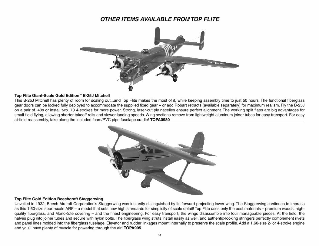
31
OTHER ITEMS AVAILABLE FROM TOP FLITE
Top Flite Giant-Scale Gold Edition™ B-25J MitchellThis B-25J Mitchell has plenty of room for scaling out...and Top Flite makes the most of it, while keeping assembly time to just 50 hours. The functional fi berglass gear doors can be locked fully deployed to accommodate the supplied fi xed gear – or add Robart retracts (available separately) for maximum realism. Fly the B-25J on a pair of .40s or install two .70 4-strokes for more power. Strong, laser-cut ply nacelles ensure perfect alignment. The working split fl aps are big advantages for small-fi eld fl ying, allowing shorter takeoff rolls and slower landing speeds. Wing sections remove from lightweight aluminum joiner tubes for easy transport. For easy at-fi eld reassembly, take along the included foam/PVC pipe fuselage cradle! TOPA0980
Top Flite Gold Edition Beechcraft StaggerwingUnveiled in 1932, Beech Aircraft Corporation’s Staggerwing was instantly distinguished by its forward-projecting lower wing. The Staggerwing continues to impress as this 1.60-size sport-scale ARF – a model that sets new high standards for simplicity of scale detail! Top Flite uses only the best materials – premium woods, high-quality fiberglass, and MonoKote covering – and the finest engineering. For easy transport, the wings disassemble into four manageable pieces. At the field, the halves plug into joiner tubes and secure with nylon bolts. The fiberglass wing struts install easily as well, and authentic-looking stringers perfectly complement rivets and panel lines molded into the fiberglass fuselage. Elevator and rudder linkages mount internally to preserve the scale profile. Add a 1.60-size 2- or 4-stroke engine and you’ll have plenty of muscle for powering through the air! TOPA905