waste heat recovery system (whrs) for cement … · key words:cement plant, rotary kiln system,...
TRANSCRIPT

Fac.Of Eng. LOGO
National Cement Comp. LOGO
WASTE HEAT RECOVERY SYSTEM (WHRS) FOR CEMENT INDUSTRY - A
CASESTUDY FOR HADHRAMOUT CEMENT FACTORY, ARABIAN YEMEN
CEMENT COMPANY LIMITED (AYCCL) – MUKALLA – HADHRAMOUT
Salem Mohammed Bin Qadhi(1), and AbdullahAbdulRaheemBawazir.(2)
(1) Mechanical Engineering Consultant – Seiyun – Hadhramout - Yemen
(2) Reliability Engineer, Arabian Yemen Cement Company – Mukalla –
Hadhramout - Yemen
Key words:Cement Plant, Rotary kiln system, Energy Balance, Heat Balance, Heat Recovery
Abstract
Waste Heat Recovery (WHR) is the process of recovering heat dischargedas a byproduct of
one process to provide heat needed by a second process. So it is the capture and the use of
energy contained in fluids or gasses that would otherwise be lost to a facility. Insimplistic
terms, waste heat can be interpreted as heat rejected heatthat has already been paid for and is
now being rejected from afacility to the environment. This heat still has energy and
usefulnessto the facility in terms of preheating another process or coolingusing absorption
system or heating a building. Recovery and reuse ofthis heat has the potential for significant
reduction of energy costsand improving the profitability of any business. Engineers
haveintensive research work in taking a systematic approach to definingand implementing
waste heat recovery projects for industrial,commercial, and institutional facilities where these
opportunitiesexist.
Among these facilities where (WHRS) has potential is the Cement Industries. Cement
industry is considered from the important industries inYemen. As this industry is directly
related with building andconstruction industries in the country. In Yemen there are eight
cement factories distributed in different parts of the country. Cementindustry is one of the
high energy consuming industries.
The specific average energy consumption is estimated as 100 – 150equivalent kg of oil per
produced ton of cement, and the energy costmay reach 40 – 60% of the total production cost.
To ensure the proper selection of the right waste heat recoverysystem(WHRS) technologies,
their correct dimensioning and smartpositioning, all of which leads to enormous savings in
money and addsup to a significant enhancement in a plants’ economy, Lower capitaland
operation costs.
Waste Heat recovery in cement industry is the use of the waste heatfrom furnace(kiln) and the
clinker in the preheating processes.In this study the energy saving using heat exchanger heat

P a g e | 2
recoverysystem for the Arabian Yemen Cement Company Limited (AYCCL) forpre-heating
processes is considered. Data of Mukalla weather has beenused as the basis of this analysis.
Other technical data for thedifferent heat equipment are taken from site i.e. (AYCCL).
It can be concluded that heat recovery system provedits importance in the cement industry
application where there is apossibility of heat recovery from the exhaust air from the
furnaceburning process and the Clinker to the preheating processes.
Findings showed that approximately 13.3% of the total input energy could be recovered; (7.5
MW) (in case of steam cycle),For the kiln surface, a secondary shell system has been
proposed and designed.
Therefore, it is recommended to use the Waste heat recovery system (WHRS) incement
industry in Yemen so as to achieve energy saving as well as toreduce the running cost of the
system beside the other advantages.
P a g e | 3
Contents: Page
1. Introduction 5
2. Basic Concept 6
3. Waste heat availability 6
4. Energy auditing and heat recovery 7
4.1 Data Gathering and main (thermal) calculations. 7
4.2 Mass balance 11
4.3 Energy balance: 11
4.4 Kiln system efficiency & waste heat. 12
4.5 Sources of waste heat 12
4.5.1 Exhaust gas from the kiln terminal (22%), 12
4.5.2 Exhaust gas from the head of the kiln (7.6%) 12
4.5.3 Heat diffusion from cement kiln shell (7 %) 12
5. Waste heat recovery system 12
5.1 The second generation of WHR power generation technology 13
5.1.1 Characteristics of the second generation system. 13
5.2 Thermal calculations. 14
5.3 System Description (process): 17
6. Heat recovery from kiln surface 17
7. Energy & Cost savings with some major Benefits. 20
7.1 Benefits by Energy Saving (Summary) 20
8 Results & Conclusions 20
9 References 21
List of Figures:
1 Schematic of Waste Heat Recovery for Power Generation. 6
2 Control volume, various streams and components for kiln system 8
3 Mass balance of the kiln system 8
4 Sankey diagram of energy balance 11
5 Process diagram of second generation system 13
6 Suspension Pre-heater (SP) Boiler with gas flow diagram 14
7 Air Quenching Cooler (AQC) Boiler with gas flow diagram 14
8 Process diagram with final assumption and calculation 15
9 Duct modification from first chamber of cooler. 17
10 Heat transfer modes (convection and radiation) from the rotary kiln. 17
P a g e | 4
11 Secondary shell application to the current kiln surface. 18
12 Rotary kiln covered by special insulation. (China). 19
13 Another application of kiln radiation and convection waste heat recovered for
domestic using.(China).
19
14 Distribution of cement production cost, AYCCL 2012. 20
List of Tables:
1 Raw material and clinker components and their percentages. 7
2 Complete Energy Balance of the Kiln system. 9
3 Complete thermal calculations (equations & parameters). 15
P a g e | 5
1. Introduction
Waste heat from cement kilns is usually used for drying of raw materials and fuel.
Depending on the humidity of the raw materials and the cooler technology, additional
waste heat is available from the kiln gases (pre-heater exit gas) and cooler exhaust air.
This heat can be used for steam and electric power production.Waste heat recovery from
hot gases and hot kiln surfaces in a kiln system are known as potential ways to improve
overall kiln efficiency [3].
There are several exhaust streams in the cement manufacturing operation that contain
significant amounts of heat energy,including the kiln exhaust, clinker cooler, and kiln pre-
heater and pre-calciner. In certain cases, it may be cost effective to recover a portion of
the heat in these exhaust streams for power generation. Power generation can be based on
steam cycle or organic Rankin Cycle (I.e. conversion of heat into work). In each case a
pressurized working fluid (Water for steam cycle or an organic compound for the organic
Rankin cycle) is vaporized by the hot exhaust gases in the heat recovery boiler, or heater,
and then expanded through a turbine that drives a generator. Based the heat recovery
system and kiln technology, 7 – 8 kWh/ ton cement can be produced from hot air from the
clinker cooler, and 8 – 10 kWh/ ton cement from kiln exhaust[12]. Total power generation
can range from 7 -20 kWh/ ton cement. Steam turbine heat recovery system were
developed and first implemented in Japan and are being widely adopted in Europe and
China [11]. Installation costs for steam system ranges from $ 2 -4? Annual ton cement
capacity with operating costs ranging from $ 0.2 – 0.3 /annual cement capacity [12].
Generally, only long dry kilns produce exhaust gases with temperature high enough to
make heat recovery for power economical. Heat installation in Europe and China has
included long dry kilns with pre-heater. Heat recovery for power generation may not
possible at facilities where the waste heat is used to extensively dry the raw materials; it is
usually more economic and efficient to use the exhaust heat to reduce the moisture content
of raw materials with very high moisture [12].
It is possible to meet 25- 30 % of the plants total electrical needs through this type of
cogeneration. An example, a 4100 ton/day cement plant in India, installed a waste heat
recover power plant using the exhaust from preheater and clinker cooler. The power plant
was rated at 8 megawatt (MW). Capital investment was 18.7 million, and CO2 emission
reductions were reported to be 49000/ yr. [13].
This paper focuses on the energy recovery of a horizontal rotary kiln system, which has
been used in the Arabian Yemen Cement Company Ltd (AYCCL) Hadhramout Yemen
4000 ton/day. A detailed thermodynamic analysis of the kiln system is first given, and
then, possible approaches of heat recovery from some major heat loss sources are
discussed.
Heat recovery options can be broadly classified into three strategies: • Recycling energy back into the process. • Recovering energy for other on-site uses. • Using it to generate electricity in combined heat and power systems
P a g e | 6
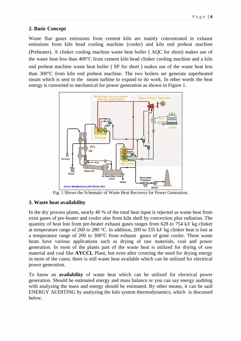
2. Basic Concept
Waste flue gases emissions from cement kiln are mainly concentrated in exhaust
emissions from kiln head cooling machine (cooler) and kiln end preheat machine
(Preheater). A clinker cooling machine waste heat boiler(AQC for short) makes use of
the waste heat less than 400°C from cement kiln head clinker cooling machine and a kiln
end preheat machine waste heat boiler(SP for short)makes use of the waste heat less
than 300°C from kiln end preheat machine. The two boilers set generate superheated
steam which is sent to the steam turbine to expand to do work. In other words the heat
energy is converted to mechanical for power generation as shown in Figure 1.
Fig. 1 Shows the Schematic of Waste Heat Recovery for Power Generation.
3. Waste heat availability
In the dry process plants, nearly 40 % of the total heat input is rejected as waste heat from
exist gases of pre-heater and cooler also from kiln shell by convection plus radiation. The
quantity of heat lost from pre-heater exhaust gases ranges from 628 to 754 kJ/ kg clinker
at temperature range of 260 to 280 °C. In addition, 209 to 335 kJ/ kg clinker heat is lost at
a temperature range of 200 to 300°C from exhaust gases of grate cooler. These waste
heats have various applications such as drying of raw materials, coal and power
generation. In most of the plants part of the waste heat is utilized for drying of raw
material and coal like AYCCL Plant, but even after covering the need for drying energy
in most of the cases, there is still waste heat available which can be utilized for electrical
power generation.
To know an availability of waste heat which can be utilized for electrical power
generation. Should be estimated energy and mass balance or you can say energy auditing
with analyzing the mass and energy should be estimated. By other means, it can be said
ENERGY AUDITING by analyzing the kiln system thermodynamics, which is discussed
below.

P a g e | 7
4. Energy auditing and heat recovery
4.1 Data Gathering and main (thermal) calculations.
Table 1 : Raw material and clinker components and their percentages*
Component Raw Materials, % Clinker, %
SiO2, % 13.15 22.25
Al2O3, % 3.76 5.50
Fe2O3, % 1.94 3.90
CaO, % 43.25 66.00
MgO, % 1.25 1.65
K2O, % 0.12 0.2
Na2O, % 0.05 0.18
SO3, % 0.30 0.33
H2O, % 1.31 -
Organics 0.90 -
Ignition loss 35.97 -
Total 100.00 100.00
* Ref. Ayccl Lab.
P a g e | 8
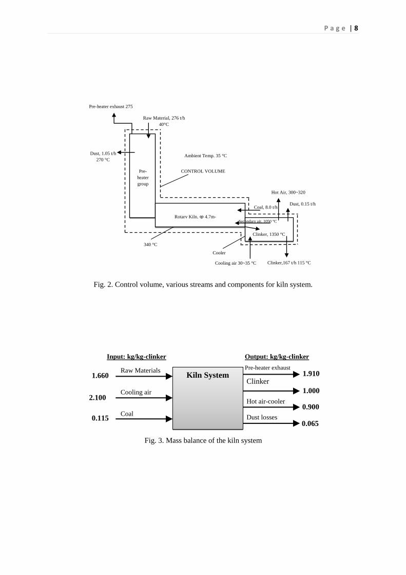
Fig. 2. Control volume, various streams and components for kiln system.
Fig. 3. Mass balance of the kiln system
Clinker, 1350 °C
Secondary air, 1050 °C
Pre-heater exhaust 275
°C °C Raw Material, 276 t/h
40°C
Cooler
CONTROL VOLUME
Dust, 1.05 t/h
270 °C
Clinker,167 t/h 115 °C
Rotary Kiln, ϕ 4.7m-
74m
Coal, 8.0 t/h
Hot Air, 300~320
°C
Ambient Temp. 35 °C
Dust, 0.15 t/h
340 °C
Cooling air 30~35 °C
Pre-
heater
group
Kiln System Raw Materials
Cooling air
Coal
Pre-heater exhaust
Hot air-cooler
Dust losses
1.660
2.100
0.115
1.910
0.900
1.000
Clinker
0.065
Input: kg/kg-clinker Output: kg/kg-clinker

P a g e | 9

Table. 2 Complete Energy Balance of the Kiln system.
Q.
Sr. Description Equations used Data
Result (KJ/Kg-
clinker)
(Kcal/Kg-
clinker) %
Heat inputs :
1 Combustion of coal
mc = 0.115 kg/kg cli , Hc = 23028.5
kJ/kg 2792.06 666.84 94.57
2 Sensible heat by coal
mc = 0.115 kg/kg cli , C = 1.15 kJ/kg
°C , T = 50°C 6.61 1.58 0.22
3 Heat by raw material
mrm= 1.667 kg/kg cli , C = 0.86 kJ/kg
°C , T = 50°C 71.68 17.12 2.43
4 Organics in the kiln
feed F = 0.10, hoc= 21036 kJ/kg, K = 0.9 %
(Ref.[ ]) 18.93 4.52 0.64
5 Heat by cooling air
mca= 2.1 kJ/kg cli , hca = 30 kJ/kg, (T =
50°C ) 63.00 15.05 2.13
Total heat input 2952.29 705.11 100.0
Heat outputs :
6 Formation of clinker
(Clinker composition is given in Table
1) 1762.65 420.98 59.70
7 Kiln exhaust gas
meg= 2.094 kJ/kg cli , Cp-eg= 1.1071
kJ/kg °C ) , T = 275°C 637.47 152.25 21.59
8 Moisture in raw
material and coal
mH2O= 0.008835 kg/kg cli (in coal+raw
material) ,hfg(50ºC)= 2591 J/kg , h(50ºC) =
2384 J/kg , h(276ºC)= 3104 J/kg
16.53 3.95 0.56
9 Hot air from cooler
=0.940 kg/kg cli , =
220 kJ/kg °C ) ,T = 300°C 216.20 51.64 7.32
10 Heat loss by dust
=0.042 kg/kg cli ,
= 0.006 kg/kg cli ) ,
= 275 kJ/kg (Ref.[7])
13.20 3.15 0.45
11 Clinker discharge
= 1 kg/kg cli , = 86 kJ/kg ,
(Ref.[7]) 86.00 20.54 2.91

P a g e | 11
12
Convection &
Radiation from kiln
surface )
h = combine Convection & Radiation
coff. From chart. = 21.5 kcal/m2 C hr ,
A = 1092 m2 ,T = 300 ,Ta = 35 C ,
= 166666.67 kg/h (Ans. X 4.18)
184.14 43.98 6.24
13
Convection &
Radiation from cooler
surface )
h = combine Convection & Radiation
coff. From chart. = 12.5 kcal/m2 C hr ,
A = 230 m2 ,T = 120 ,Ta = 35 C ,
= 166666.67 kg/h (Ans. X 4.18)
6.14 1.47 0.21
14 Unaccounted losses 29.96 7.16 1.01
Total heat output 2952.29 705.11 100.0
Overall system Thermal Efficiency or (Energy efficiency for the kiln system) η =59.70 %

Fig. 4Sankey diagram of energy balance
4.2. Mass balance
The average compositions for dried coal and pre-heater exhaust gas are shown in Fig. 2.
Based on the coal composition, the net heat value has been found to be 24278.8 kJ/kg-
coal. It is usually more convenient to define mass/energy data per kg clinker produced per
unit time. The mass balance of the kiln system is summarized in Fig. 3. All gas streams
are assumed to be ideal gases at the given temperatures.
4.3 Energy balance:
In order to analyze the kiln system thermodynamically, the following assumptions are
made:
1. Steady state working conditions.
2. The change in the ambient temperature is neglected.
3. Cold air leakage into the system is negligible.
4. Raw material and coal compositions do not change.
5. Averaged kiln surface temperatures do not change.
Based on the collected data from AYCCL site, an energy balance is applied to the kiln
system. The physical properties and equations can be found in Peray’s handbook [1]. The
reference enthalpy is considered to be zero at 0 °C for the calculations. The complete
energy balance for the system is shown in Table 2. It is clear from Table 2 that the total
energy used in the process is 2952.29 kJ/kg-clinker, and the main heat source is the coal,
giving a total heat of 2792.07 kJ/kg-clinker (94.57%). Also, the energy balance given in
Table 2indicates relatively good consistency between the total heat input and total heat
output. Since most of the heat loss sources have been considered, there is only a 30 kJ/kg-
clinker of energy difference from the input heat; this difference is nearly 1.01% of the
21
.59 %
7.3
2 %
6.2
4 %
1.0
1 %
0.5
6 %
0.4
5 %
0.2
1 %
10
0 %
59
.70 %
Kiln exhaust gas
Hot air from cooler
Convection & Radiation from kiln surface
Unaccounted losses
Moisture in raw material and coal
Heat loss by dust
Convection & Radiation
from cooler surface
Use
ful
En
erg
y (
clin
ker
form
atio
n e
ner
gy
)
Raw
Mat
eria
ls,
coo
lin
g
air,
co
al,
mo
istu
re

P a g e | 13
total input energy and can be attributed to the assumptions and nature of data. The
distribution of heat losses to the individual components exhibits reasonably good
agreement with some other key plants reported in the literature [3].
4.4 Kiln system efficiency & waste heat.
The overall system efficiency can be defined by η =Q6/QTotal input = 1762.65/2952.29 =
0.597or 59.7%, which can be regarded as relatively low. The overall efficiency of the kiln
system can be improved by recovering some of the heat losses. The recovered heat energy
can then be used for several purposes, such as electricity generation and preparation of hot
water.
4.5 Sources of waste heat
Large amounts of coal are consumed in the production of cement, especially in the
calcination process.so the temperature of the exhaust gas from the kiln head to the back
end is very high, so the recovery of the waste heat is necessary to improve the energy
utilization efficiency. The places which released heat are discussed below.
4.5.1 Exhaust gas from the kiln terminal (22%),
The temperature of the exhaust gas from the kiln terminal is about 275°C. This heat can
be reused by employing a waste heat recovery system.
4.5.2 Exhaust gas from the head of the kiln (7.6%)
The temperature of the exhaust gas at the kiln head is about 300°C, which is high enough
for a waste heat recovery system to be useful at exist condition (w/out modification
which it showed in Fig. 9 Sec. 5.3 to getting some improvement.
4.5.3 Heat diffusion from cement kiln shell (7 %)
The cement rotary kiln is the primary place where the calcination process occurs, so most
of the energy is consumed here. The temperature in the kiln needs to be about 1450°C to
ensure that the cement producing process is functioning properly. The temperature of the
kiln shell surface is also very high and can be up to 350°C with a mean temperature of
about 300°C. Between heat convection and radiation, much heat is released into the
atmosphere. Fire bricks are set around the kiln to prevent heat dissipation; but the kiln
shell cannot tolerate temperatures higher than 400°C. So at the same time, excess heat in
the kiln shell must be promptly radiated away.
5. Waste heat recovery system
The thermodynamic cycle system that is most suitable to convert waste heat into power
is the Rankine cycle in its various working fluid-specific forms:
Traditional water-steam Rankine cycle.

P a g e | 14
Organic Rankine cycle (ORC).
Ammonia-water Rankine cycle (The so-called Kalina cycle).
Because the temperature of the exhaust gas is not high especially at Pre-heater exhaust
gas, the efficiency of the waste heat recovery system is limited. Kalina cycle is thought to
have better performance for electricity generation by recovering low-temperature waste
heat than other cycles [4], and the reasons for selection Kalina Cycle will be introduced in
sec.7.
A waste heat boiler for cement plants has been studied by many researchers, and this
mature technology is already used in the cement industry.
In this study, a suspension pre-heater (SP) boiler was placed at the back end of the kiln
to recover heat from the exhaust gas at 270°C and an air quenching cooler (AQC) boiler
was added to recover the heat of the exhaust gas from the clinker cooler at 380°C (after
exhaust system modified).The inlet air of the SP boiler comes from the final stage of the
pre-heater (C1-stage), and its temperature is about 260°C–280°C.
5.1The second generation of WHR power generation technology
5.1.1 Characteristics of the second generation system.
For most (over 80%) AQC of production lines that had been completed can absorb heat in
380-400°C or even higher, the systems which the outlet temperature of SP C1 cyclone is
below 330°C will send the low-temperature superheated steam (below 300°C) like our
plant (AYCCL) from SP boiler to AQC boiler, the AQC boiler has a superheater which
can mix the steam (from AQC and SP boilers) and heat it to 360-380°C (the temperature
will increase 50-60°C than original steam), and then, the heated steam will enter the
turbine to generate power. This process can improve the power generation by around 8-
10% than the first processFig.5 shows process diagram of second generation system [5 ] .

P a g e | 15
Fig. 5.Illustrate Process diagram of second generation system
Fig. 6. Shows Suspension Pre-heater (SP) Boiler with gas flow diagram

P a g e | 16
Fig. 7. Shows Air Quenching Cooler (AQC) Boiler with gas flow diagram
5.2 Thermal calculations.
The basic data of the cement plant is given below. The data is based on standard
engineering practices.
1) The data is based on a dry process cement plant with a cement output of 4000 t/d
clinker.
2) The energy consumption of the clinker is 2952.29 kJ/kg. The temperature of the raw
mill drying process is 125°C & coal mill 170°C.
3) The flow rate of the exhaust gas from the kiln terminal is 281,670N m3/h (Calculated
330,000 Nm3/h for one ID fan). The mean temperature is 275°C, but decreases to 185 °C
when it leaves the SP boiler.
4) The exhaust gas from the kiln head is 391,000 Nm3/h and the average temperature is
300°C, which decreases to 185°C when it leaves the AQC boiler.
5) The mean temperature of the cement kiln shell is about 320°C.
6) The Boiler, Turbine and generator efficienciesare set as 85%, 85 % & 89 %
respectively.
The calculation results show that the generating capacity of the whole system is 7.5MW,
these calculations for traditional steam cycle, Figure 8 shows process diagram with final
assumptions and calculations.

P a g e | 17
Fig. 8 Shows process diagram with final assumption and calculation
Table 3:Show complete thermal calculations(equations & parameters)
SP Boiler
Designation Unit Quantity Note and additional information
Input Data :
Mass of hot gases, m³/hr 281670 As per calculation 361,418 m³/hr , but we
consider 281,670 m³/hr (78%)
Temp. of hot gases, Tg °C 270
Stack Temp. (first assumption) °C 100
Stack Temp. (after balancing) °C 184.89
Density, ρ Kg/m³ 1.2 Fan Designer used 1.422 (ideal condition
Sp. Heat.,Cp. KJ/kgk 1.04
WHR Boiler Efficiency - 0.85 Assumed
Boiler Pressure Bar 10 Assumed
Superheated Temp. °C 250 choose after trial methods,
Enthalpy for superheated steam, h KJ/kg 2942.6 From Steam tables at 10 bar & 220 °C
Inlet water to boiler, °C 35 Assumed
Enthalpy for inlet water, h KJ/kg 146.6 From Steam tables at 35 °C
Saturated Temp.,tst °C 179.88 From Steam tables at 10 bar
Punch Temp.tp
°C 184.88 + 5 deg.
Sensible heat, h KJ/kg 762.5 From Steam tables at 10 bar
Calculations:
1) Quantity of heat available kW 16599.752 Q=mCp(tg-ts)
2) Mass of steam kg/s 5.05 Boiler eff. = ( mass of steam)(change of
enthalpy in boiler)/heat supplied.
AQC Boiler + Seam Plant
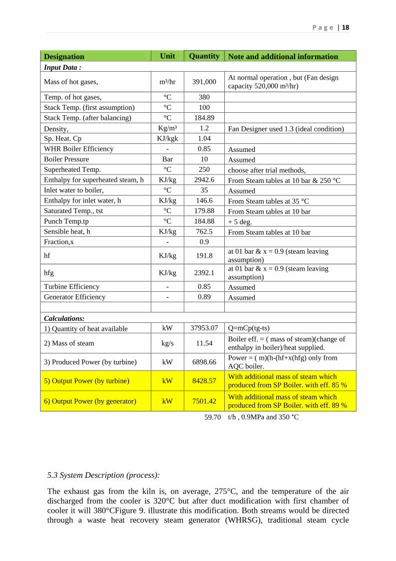
P a g e | 18
Designation Unit Quantity Note and additional information
Input Data :
Mass of hot gases, m³/hr 391,000 At normal operation , but (Fan design
capacity 520,000 m³/hr)
Temp. of hot gases, °C 380
Stack Temp. (first assumption) °C 100
Stack Temp. (after balancing) °C 184.89
Density, Kg/m³ 1.2 Fan Designer used 1.3 (ideal condition)
Sp. Heat. Cp KJ/kgk 1.04
WHR Boiler Efficiency - 0.85 Assumed
Boiler Pressure Bar 10 Assumed
Superheated Temp. °C 250 choose after trial methods,
Enthalpy for superheated steam, h KJ/kg 2942.6 From Steam tables at 10 bar & 250 °C
Inlet water to boiler, °C 35 Assumed
Enthalpy for inlet water, h KJ/kg 146.6 From Steam tables at 35 °C
Saturated Temp., tst °C 179.88 From Steam tables at 10 bar
Punch Temp.tp °C 184.88 + 5 deg.
Sensible heat, h KJ/kg 762.5 From Steam tables at 10 bar
Fraction,x - 0.9
hf KJ/kg 191.8 at 01 bar & x = 0.9 (steam leaving
assumption)
hfg KJ/kg 2392.1 at 01 bar & x = 0.9 (steam leaving
assumption)
Turbine Efficiency - 0.85 Assumed
Generator Efficiency - 0.89 Assumed
Calculations:
1) Quantity of heat available kW 37953.07 Q=mCp(tg-ts)
2) Mass of steam kg/s 11.54 Boiler eff. = ( mass of steam)(change of
enthalpy in boiler)/heat supplied.
3) Produced Power (by turbine) kW 6898.66 Power = ( m)(h-(hf+x(hfg) only from
AQC boiler.
5) Output Power (by turbine) kW 8428.57 With additional mass of steam which
produced from SP Boiler. with eff. 85 %
6) Output Power (by generator) kW 7501.42 With additional mass of steam which
produced from SP Boiler. with eff. 89 %
59.70 t/h , 0.9MPa and 350 °C
5.3 System Description (process):
The exhaust gas from the kiln is, on average, 275°C, and the temperature of the air
discharged from the cooler is 320°C but after duct modification with first chamber of
cooler it will 380°CFigure 9. illustrate this modification. Both streams would be directed
through a waste heat recovery steam generator (WHRSG), traditional steam cycle

P a g e | 19
considered here, and the available energy is transferred to water via the WHRSG. The
schematic of a typical WHRSG cycle is shown in Fig.5. The available waste energy is
such that steam would be generated. Because of various losses and inefficiencies inherent
in the transfer of energy from the gas stream to the water circulating within the WHRSG,
not all of the available energy will be transferred. A reasonable estimate on the efficiency
of the WHSRG must be made. The Boiler, Turbine & generator efficiencies are set as
85%, 85 % & 89 % respectively. As the gas passes through the WHRSG, energy will be
transferred and the gas temperature will drop. Targeting a pressure of 10 bars at the
turbine inlet. The minimum stream temperature at the WHRSG’s exit would be higher
than the corresponding saturation temperature, which is roughly 180 °C. As a limiting
case, we assume the exit temperatures to be 185°C. After exiting the WHRSG, the energy
of those streams can be recovered by using a compact heat exchanger. Hence, the final
temperature can be reduced as low as possible.
According to the final temperatures of both streams, the final enthalpies have been
calculated. Therefore, the available heat energy would be:
Q = 7501.42 kW = 7.5 MW
The next step is to find a steam turbine generator set that can utilize this energy. Since a
steam turbine is a rotating piece of machinery, if properly maintained and supplied with a
clean supply of dry steam. Considering steam turbine generator set 1000 kW. If we
assume that the useful power generated is 6500 kW = 6.5 MW.
Fig.9.Illustrate duct modification from first chamber of cooler.
6. Heat recovery from kiln surface
The hot kiln surface is another significant heat loss source,
and the heat loss through convection and radiation dictates
a waste energy of 6.3% of the input energy. On the other
hand, the use of a secondary shell on the kiln surface can
significantly reduce this heat loss. Since the kiln surface
needs to be frequently observed by the operator so as to see
any local burning on the surface due to loss of refractory
inside the kiln, we would not consider insulating the kiln surface, unless found a good
solution for this issue.
Fig.10 Illustrated Heat transfer
modes (convection and
radiation) from the rotary kiln
≈600
°C
391,000 m3/hr. 380 °C
≈320 °C
Damper gate for
temp.controlwhe
n hot air mixed
≈700
°C
≈800
°C
≈900
°C
≈1050
°C

P a g e | 20
The basic principle of the secondary shell is shown in Fig. 11. For the current rotary kiln,
, a radius of can be considered and Kiln surface area
will be = 819.5 m2 (for 75% as effective area). Since the distance between the two
surfaces is relatively small (440 mm), a realistic estimation for the temperature of the
secondary shell can be made. We assume T2 = 300 °C =573 K. We would consider
stainless steel for the material of the secondary shell since it has relatively low surface
emissivity and thermal conductivity. The heat transfer rate by radiation is then calculated
using the following equation [1]:
Where σ = 5.67 x 10 -8 W/m2K4 , T1=Ts=613 K, ɛ1 = 0.78 (for oxidized kiln surface)
and ɛ2 = 0.35 (lightly oxidized stainless steel).
Qr≈ 521kW
This heat loss is to be transferred through the insulation on the secondary shell. Therefore,
assuming a reasonable temperature for the outer surface of the insulation, we can
determine the required thickness of insulation. For glass wool insulation, the thermal
conductivity is taken as 0.05 W/m K. Therefore, the resistance of the insulation layer
would be,
Fig. 11. Secondary shell application to the current kiln surface.
Assuming a temperature difference of ∆Tins = 240 °C (which means an outer surface
temperature of 60 °C) Rins can be determined:
∆Tins = Q (resistance of insulation)

P a g e | 21
We found Rins =2.6 m, and the thickness of insulation would be
e = Rins - Rshell = 0.1 m = 10 cm
It should be noted that when the secondary shell is added onto the kiln surface, the
convective heat transfer would presumably become insignificant. This is because of the
fact that the temperature gradient in the gap would be relatively very low, e.g., 0.45°C/cm
[1]. Therefore, the total energy savings due to the secondary shell would be
(184.14 kJ/kg-clinker) (46.3 kg-clinker/s) = 8525.7 kWfrom the convective & radiation
heat transfer.
Therefore, we can safely conclude that the use of a secondary shell on the current kiln
surface would save at least 8.5 MW, which is 6.3% of the total input energy. This energy
saving would result in a considerable reduction of fuel consumption (almost 6.5 %) of the
kiln system, and the overall system efficiency would increase by approximately 5%.
Fig.12Shows Rotary Kiln covered by special insulation. (China)
Fig.13 Shows another application of kiln radiation and convection waste
heat recovered for domestic using.(China)
7. Energy & Cost savingswith some major Benefits.
Normally, more than half of the cost of cement production is spent on energy
consumption. It will be much more if the cost of energy goes up. Therefore, the project of

P a g e | 22
using waste heat to generate electricity is a fairly good way to cut down the whole
production cost. Figure. 16 Shows the mix of cement production cost (AYCCL 2012).
Fig. 14 Distribution of cement production cost, AYCCL 2012
7. Benefits by Energy Saving (Summary):
Increase overall thermal use efficiency4.8-6.4 %.
Waste heat power generation amount 39-52 kWh per ton clinker.
Lower clinker cost 7-10 % $ / ton from exist cost.
Annual energy saving 50-70 % kWh from existenergy.
The waste heat power generation system will also help to decrease the
generation of CO2 generationup to 33%-50% emission reduced. [9]
8. Results & Conclusions
A detailed energy audit analysis, which can be directly applied to any dry kiln system, has
been made for a specific key cement plant. The distribution of the input heat energy to the
system components showed good agreement between the total input and output energy
and gave significant insights about the reasons for the low overall system efficiency.
According to the results obtained, the system efficiency is 59.7 %. The major heat loss
sources have been determined as kiln exhaust (22 % of total input), cooler exhaust (7.6%
of total input) and combined radiative and convective heat transfer from kiln surfaces (7
% of total input). For the first two losses, a conventional WHRSG system is proposed.
Calculations showed that 7.5 MW of energy could be recovered (in case of steam cycle),
but 9.75 MW (in case of Kalina Cycle). For the kiln surface, a secondary shell system has
been proposed and designed. It is believed that the use of this system would lead to 8.5
MW of energy saving from the kiln surface.

P a g e | 23
The payback period for the two systems is expected to be less than 1.5 year in the first
case and less than 2.5 years in second case.
The above results are obtained using the provided data and their calculations, they may
vary depending upon plant conditions and other economics factors.
9. References:
[1]Peray KE. Cement manufacturer’s handbook. New York, NY: Chemical Publishing
Co., Inc.; 1979.
[2]Cengel YA. Heat transfer-A practical approach. 2nd ed. New York, NY: McGraw-Hill;
2003.
[3]TahsinEngin, Vedat Ari Energy auditing and recovery for dry type cementrotary kiln
systems––A case study, 2004 Elsevier Ltd. [4] Mark D. Mirolli , The Kalina Cycle For Cement Kiln Waste Heat Recovery Power
Plants, (c)2005 IEEE.
[5] Nanjing Kaineng Environment & Energy Co. ltd Website:
http://en.njkskn.com/Technology_1.aspx?id=3020
[6] AnhuiNingguo Cement Plant (2002): The report on power generation by waste heat of
the kiln in Ningguo Cements Plant. Website:
http://green.cei.gov.cn/doc/LY31/200204192475.htm (in Chinese).
[7] http://www.intermountaincleanenergy.org/cleanenergy/
[8]NCB, Cogeneration of Power Utilizing Waste Heat in Cement
Manufacture:TechnologicalPerspectives.New Delhi, 21-24 November 2000.
[9]Em-G-Em Engineering& Consultants Pvt_Ltd. Website: http://www.em-g-
em.com/index.html
[10]Sameer Bhardwaj, Future Trend waste heat recovery in cement plants.GreenCemtech
, Hyderabad,2010.
[11] US EPA, Available and Emerging Technologies for Reducing Greenhouse Gas
Emissions from the Portland Cement
Industry , Oct. 2010.
[12] Worrell, Ernst and Galitsky, Christina, 2008. “Energy Efficiency Improvement and
Cost Saving Opportunities for Cement Making” (Report No. LBNL-54036-Revision),
Ernest Orlando Lawrence Berkeley National Laboratory, Berkeley, CA. March 2008.
http://www.energystar.gov/ia/business/industry/LBNL-54036.pdf
[13] Portland Cement Association (PCA), 2008. “Carbon Dioxide Control Technology
Review,” Report No. PCA R&D SN3001, Portland Cement Association, Skokie, IL.
http://www.cement.org/bookstore/profile.asp?store=&pagenum=&pos=0&catID=&id=16
705