waste treatment and immobilization plant chapter 4g direct …
TRANSCRIPT

WA7890008967
Hanford Facility RCRA Permit Dangerous Waste Portion
Change Control Log Waste Treatment and Immobilization Plant
WASTE TREATMENT AND IMMOBILIZATION PLANT CHAPTER 4G
DIRECT-FEED LOW-ACTIVITY WASTE (EFFLUENT MANAGEMENT FACILITY)
CHANGE CONTROL LOG
Change Control Logs ensure that changes to this unit are performed in a methodical, controlled,
coordinated, and transparent manner. Each unit addendum will have its own change control log with a
modification history table. The “Modification Number” represents Ecology’s method for tracking the
different versions of the permit. This log will serve as an up to date record of modifications and version
history of the unit.
Modification History Table
Modification Date Modification Number
05/17/2018 8C.2018.2F
09/05/2017 8C.2017.6F
12/15/2016 8C.2016.Q3

WA7890008967
Hanford Facility RCRA Permit Dangerous Waste Portion
Change Control Log Waste Treatment and Immobilization Plant
This page intentionally left blank.
WA7890008967
Waste Treatment and Immobilization Plant
Chapter 4G.i
1
CHAPTER 4G 2
DIRECT FEED LOW-ACTIVITY WASTE (EFFLUENT MANAGEMENT FACILITY) 3 4
5

WA7890008967
Waste Treatment and Immobilization Plant
Chapter 4G.ii
1
2
3
This page intentionally left blank. 4
5
WA7890008967
Waste Treatment and Immobilization Plant
Chapter 4G.iii
1
CHAPTER 4G 2
DIRECT FEED LOW-ACTIVITY WASTE (EFFLUENT MANAGEMENT FACILITY) 3 4
5
TABLE OF CONTENTS 6
Direct Feed Low-Activity Waste (Effluent Management Facility) ........................................... 5 7
Containers ................................................................................................................................ 87 8
Tank Systems ............................................................................................................................ 7 9
4G.2.1 Low-Point Drain Vessel (DEP-VSL-00001) ............................................................................. 7 10
4G.2.2 Evaporator Feed Vessel (DEP-VSL-00002) ............................................................................. 8 11
4G.2.3 Evaporator Concentrate Vessels (DEP-VSL-00003A/B/C) ...................................................... 8 12
4G.2.4 Overhead Sampling Vessels (DEP-VSL-00004A/B) ................................................................ 9 13
4G.2.5 Process Condensate Lag Storage Vessels (DEP-VSL-00005A/B) ............................................ 9 14
Miscellaneous Units ................................................................................................................ 10 15
4G.3.1 Evaporator Separator Vessel (DEP-EVAP-00001) ................................................................. 10 16
4G.3.2 Evaporator Primary Condenser (DEP-COND-00001) ............................................................ 10 17
4G.3.3 Evaporator Inter-Condenser (DEP-COND-00002) ................................................................. 11 18
4G.3.4 Evaporator After-Condenser (DEP-COND-00003) ................................................................ 11 19
4G.3.5 Process Condensate Filter (DEP-FILT-00002) ....................................................................... 11 20
4G.3.6 Evaporator Feed Prefilter (DEP-FILT-00003) ........................................................................ 11 21
4G.3.7 Condensate Duplex Cartridge Filters (DEP-FILT-00004A/B) ............................................... 11 22
4G.3.8 Evaporator Concentrate/Feed Vessels Low-Activity Waste Effluent Cooler (DEP-HX-23
00001) ...................................................................................................................................... 11 24
4G.3.9 Evaporator Reboiler (DEP-RBLR-00001) .............................................................................. 11 25
Secondary Containment and Release Detection for Effluent Management Facility ............... 12 26
4G.4.1 Low-Point Drain Sump (DEP-SUMP-00001) ......................................................................... 12 27
4G.4.2 Pipeline Containment and Leak Detection .............................................................................. 12 28
4G.4.3 Evaporator Secondary Containment System ........................................................................... 13 29
4G.4.4 Evaporator Condenser Secondary Containment System ......................................................... 13 30
4G.4.5 Process Condensate Vessel Area Sumps (DEP-SUMP-00005A/B) ........................................ 13 31
4G.4.6 Feed Vessel Area Sumps (DEP-SUMP-00004A/B) ................................................................ 14 32
Air Emission Control ............................................................................................................... 14 33
4G.5.1 Direct Feed Low-Activity Waste Effluent Management Facility Vessel Vent Process 34
System ..................................................................................................................................... 14 35
Effluent Management Facility Process Sampling ................................................................... 14 36
37

WA7890008967
Waste Treatment and Immobilization Plant
Chapter 4G.iv
TABLES 1
Table 4G-1 Effluent Management Facility Tank Systems ..................................................................... 19 2
Table 4G-2 Effluent Management Facility Miscellaneous Units (Systems and Sub-Systems) ............. 20 3
Table 4G-3 Effluent Management Facility Secondary Containment Rooms/Areas .............................. 21 4
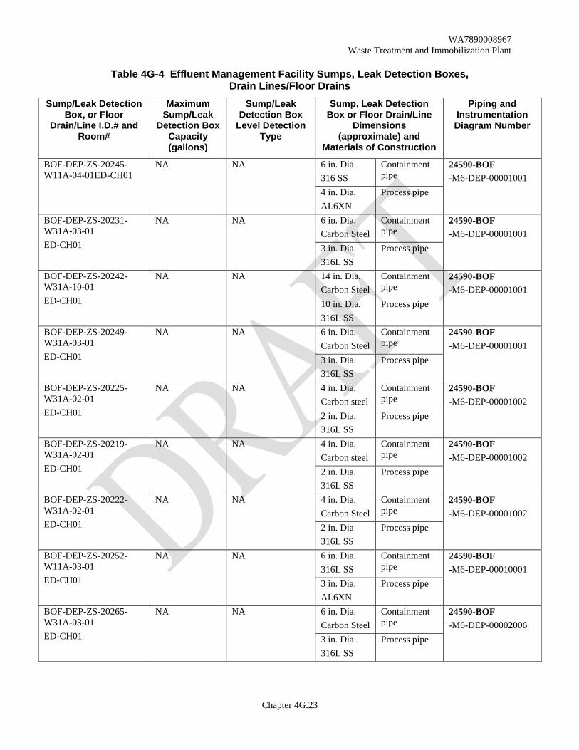
Table 4G-4 Effluent Management Facility Sumps, Leak Detection Boxes, Drain Lines/Floor Drains . 21 5
6
FIGURES 7
Figure 4G-1 Effluent Management Facility Process Flow ...................................................................... 25 8
9
10
WA7890008967
Waste Treatment and Immobilization Plant
Chapter 4G.5
Direct Feed Low-Activity Waste (Effluent Management Facility) 1
The Direct Feed Low-Activity Waste (DFLAW) configuration allows for the operation of the 2
Low-Activity Waste (LAW) Vitrification Facility and Analytical Laboratory (Lab) prior to operation of 3
the Pretreatment (PT) Facility. In this configuration, pretreated low-activity waste is fed directly from the 4
Hanford Tank Farms LAW Pretreatment System (LAWPS) to the LAW Vitrification Facility. The 5
LAWPS is permitted as a separate Treatment, Storage, and Disposal Facility under the Hanford 6
Dangerous Waste Permit. The DFLAW configuration differs from the baseline configuration. In the 7
baseline configuration, low-activity waste and high-activity waste is transferred directly from the Hanford 8
Tank Farms to the Pretreatment Facility and treated by ultrafiltration and cesium ion exchange before 9
transfer to the LAW Vitrification Facility or High-Level Waste (HLW) Vitrification Facility; in addition, 10
the generated off-gas effluents from the LAW Vitrification Facility and HLW Vitrification Facility 11
processes are returned to the Pretreatment Facility. In the DFLAW configuration, low-activity waste 12
bypasses the Pretreatment Facility and feeds directly into the LAW Vitrification Facility. As such, the 13
replication of some functions of the Pretreatment Facility is required. The Effluent Management Facility 14
(EMF) is in place to replicate activities conducted in the baseline configuration, including the 15
management and treatment of the liquid effluent from the LAW Vitrification Facility Radioactive Liquid 16
Waste Disposal (RLD) System and the Lab RLD System, and management of the effluent from the LAW 17
Secondary Offgas/Vessel Vent Process (LVP) System. Waste received at the LAW Vitrification Facility 18
from the Tank Operations Contractor (TOC)LAWPS will not be characterized as ignitable (D001) or 19
reactive (D003); therefore, tanks/vessels associated with the DFLAW configuration are not required to be 20
designed to manage reactive or ignitable wastes. 21
Permitted processes involved with the DFLAW configuration include the Direct Feed LAW EMF Process 22
(DEP) System, the Direct Feed LAW EMF Vessel Vent Process (DVP) System, and the underground 23
waste transfer lines. 24
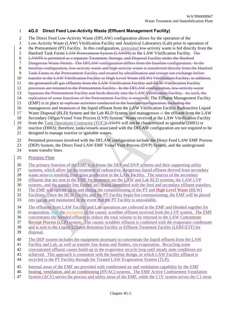
Process Flow 25
The primary function of the EMF is to house the DEP and DVP systems and their supporting utility 26
systems, which allow for the treatment of radioactive, dangerous liquid effluent derived from secondary 27
waste streams resulting from glass production in the LAW Facility. The sources of the secondary 28
effluents that are sent to the EMF for treatment are the LAW and Lab RLD systems, the LAW LVP 29
systems, and the transfer line flushes and drains associated with the feed and secondary effluent transfers. 30
The EMF will operate up to and during the commissioning of the PT and High-Level Waste (HLW) 31
Facilities. Once the HLW Facility and the PT Facility begin hot commissioning, the EMF will be placed 32
into lay-up and maintained in the event that the PT Facility is unavailable. 33
The effluents from LAW Facility and Lab operations are collected in the EMF and blended together for 34
evaporation, with the exception of the caustic scrubber effluent received from the LVP system. The EMF 35
concentrates the blended effluent to reduce the total volume to be returned to the LAW Concentrate 36
Receipt Process (LCP) system. The caustic scrubber effluent is combined with the evaporator condensate 37
and is sent to the Liquid Effluent Retention Facility or Effluent Treatment Facility (LERF/ETF) for 38
disposal. 39
The DEP system includes the equipment necessary to concentrate the liquid effluent from the LAW 40
Facility and Lab, as well as transfer line drains and flushes, via evaporation. Recycling some 41
concentrated effluent causes build-up in the evaporator recycle loop until steady state conditions are 42
achieved. This approach is consistent with the baseline design, in which LAW Facility effluent is 43
recycled to the PT Facility through the Treated LAW Evaporation System (TLP). 44
Internal areas of the EMF are provided with conditioned air and ventilation capability by the EMF 45
heating, ventilation, and air conditioning (HVAC) systems. The EMF Active Confinement Ventilation 46
System (ACV) serves the process and utility areas of the EMF, while the C1V system serves the C1 areas 47

WA7890008967
Waste Treatment and Immobilization Plant
Chapter 4G.6
that do not interface with the ACV system. The ACV system uses a cascading ventilation system that 1
maintains airflow from areas of less potential for contamination to areas of greater potential for 2
contamination to provide confinement of contamination at or near the source. Exhaust from the ACV 3
system is monitored to ensure compliance with permit requirements. 4
Figure 4G-1, EMF Process Flow, presents a simplified process flow diagram of the EMF Process. 5
Direct Feed Low-Activity Waste Effluent Management Facility Process System 6
The DEP System allows the EMF to collect, process, recycle, and dispose of the liquid effluent from the 7
Lab, LAW Vitrification Facility, and underground waste transfer line flushes. The DEP System performs 8
the following functions: 9
Receipt of liquid effluent. 10
Liquid effluent volume reduction. 11
Process stream sampling. 12
Waste conditioning. 13
The DEP System includes the following major components: 14
An evaporator system consisting of an evaporator separator vessel (DEP-EVAP-00001), 15
evaporator reboiler (DEP-RBLR-00001), evaporator condensers (DEP-COND-0001/2/3), 16
recirculation pump, and vacuum steam ejectors. 17
Low-Point Drain Vessel (DEP-VSL-00001). 18
Evaporator Feed Vessel (DEP-VSL-00002). 19
Evaporator Concentrate Vessels (DEP-VSL-00003A/B/C). 20
Overhead Sampling Vessels (DEP-VSL-00004A/B). 21
Process Condensate Lag Storage Vessels (DEP-VSL-00005A/B). 22
Other equipment, including pumps, filters, and associated piping and valves. 23
The DEP System evaporator loop functions to reduce the volume of liquid effluent that is received from 24
the LAW Vitrification Facility, Lab and underground waste transfer line flushes, and recycle the 25
concentrate back to the LAW Vitrification Facility.sent to the LERF/ETF, reduce the amount of the 26
effluent recycled, and concentrate the recycles by separating the effluents into a recycle stream and a 27
waste stream. The design also supports the transfer of the concentrate to the Hanford Tank Farms and to 28
the tanker truck load out area. Condensate from the DEP System process can be disposedtreated of at the 29
Liquid Effluent Retention Facility (LERF)/Effluent Treatment Facility (ETF). 30
The evaporator loop consists of the evaporator separator vessel, reboiler, condensers, and the recirculation 31
piping. As the liquid effluent circulates through the reboiler, the temperature rises. Then, the liquid rises 32
into the separator vessel, the hydrostatic head diminishes, and flash evaporation occurs near the liquid 33
surface. The liquid stream recirculates in the closed loop while the vapor stream enters the evaporator 34
overheads. The evaporator loop operates under a vacuum to reduce the boiling temperatures and 35
minimize corrosion. 36
The reboiler is a tube-and-shell heat exchanger. High pressure steam, supplied from the Balance of 37
Facilities (BOF), is used to heat a secondary steam loop that feeds the heat exchanger shell side, while the 38
evaporator feed circulates through the heat exchanger tubes. 39
Direct Feed Low-Activity Waste Effluent Management Facility Vessel Vent Process System 40
The DVP System is comprised of two main parts, air inlet, and exhaust. The DVP System provides 41
vessel ventilation for the DEP System vessels., tThe purpose of the DVP System is to direct vessel vent 42

WA7890008967
Waste Treatment and Immobilization Plant
Chapter 4G.7
gases to emission control systems, and purge hydrogen to maintain the vessel hydrogen concentration 1
below dangerous levels. 2
The DVP System includes the following major components: 3
Process Ventilation Preheaters (DVP-HTR-00001A/B). 4
Process Ventilation Primary High Efficiency Particulate Air (HEPA) Filters (DVP-HEPA-5
00003A/B). 6
Process Ventilation Secondary HEPA Filters (DVP-HEPA-00004A/B). 7
Process Ventilation Exhausters (DVP-EXHR-00001A/B). 8
For the DEP System vessels in the LAW Effluent Process Building, a purge air inbleed is used to meet 9
the very low required flow rates. The vessel vent is the exhaust portion of the DVP System and provides 10
suction pressure on the vessel headspace, to draw in the purge air, and mitigate hydrogen accumulation. 11
The discharged air is sent through a preheater, two-stage HEPA filters, and through an exhaust fan to 12
discharge out of the EMF stack. The DVP exhaust fans control and maintain the suction pressure inside 13
the various process vessels, maintaining the continuous purge air inbleed. 14
Underground Waste Transfer Lines 15
The underground waste transfer lines installed to support the DFLAW configuration are coaxial lines that 16
are constructed of stainless steel primary pipe, with a carbon steel encasement pipe that is coated with 17
fusion bonded epoxy (FBE). The coating system and water barrier consist of the FBE, polyurethane 18
insulation, and a jacket or thermoplastic outer water barrier made of high density polyethylene (HDPE). 19
Cathodic protection is not needed for the underground waste transfer lines installed to support the 20
DFLAW configuration as the pipe system is made of corrosion resistant materials, providing water 21
resistant construction to isolate the underground waste transfer lines from the soil and moisture. 22
The underground waste transfer lines transfer waste from various areas to support the DFLAW 23
configuration. Underground waste transfer lines support the receipt of the treated low-activity waste from 24
LAWPS to the LAW Vitrification Facility, as well as effluent transfers from LAW Vitrification Facility 25
and Lab, to the EMF and from the EMF to the LERF/ETF. Evaporator concentrate is sent back to the 26
LAW Vitrification Facility through the LAWPS underground waste transfer line. In addition, liquid 27
effluent can be transferred underground from the DEP System to the Hanford Tank Farms. After every 28
waste transfer from the LAWPS to LAW Vitrification Facility, the underground waste transfer lines are 29
flushed and drained to the EMF low-point drain vessel (DEP-VSL-00001); the effluent is collected and 30
processed at the EMF. The effluent is monitored for flow and density to minimize the volume of flush 31
liquid that is transferred to the LAW concentrate receipt vessel. 32
There are eight major Waste Treatment and Immobilization Plant (WTP) underground waste transfer lines 33
that support the EMF process. Line DEP-PB-00009-S32B-03 transfers LAWPS feed from the WTP 34
property boundary to the low-point drain vessel. Line LCP-PB-03368-S32B-03 transfers LAWPS feed 35
and EMF concentrate from the low-point drain vessel to the LAW Vitrification Facility. LAW LVP 36
process effluent and LAW RLD process effluent are transferred from the LAW Vitrification Facility to 37
the EMF through line LVP-ZY-00171-W31A-03. Lab RLD process effluent is transferred from the Lab 38
to the EMF through line RLD-WU-22142-S32B-03. Line DEP-ZS-00069-W31A-03 returns EMF 39
concentrate from the EMF to the WTP property boundary, with transfer to the Hanford Tank Farms. 40
EMF effluent is transferred to the existing LERF/ETF transfer line that connects in between the 41
Pretreatment Facility and the WTP property boundary through lines RLD-ZS-66989-W31A-04 and 42
RLD-ZS-66991-W31A-03. 43

WA7890008967
Waste Treatment and Immobilization Plant
Chapter 4G.8
Effluent Management Facility Buildings 1
The EMF, located north of the Lab, is comprised of four buildings, the LAW effluent process building, 2
the LAW effluent drain tank building, the LAW effluent electrical building, and the LAW effluent utility 3
building. The EMF contains an evaporator system, nine major process vessels, three supporting reagent 4
product storage tanks, heating, ventilation and air conditioning (HVAC) equipment, and electrical 5
utilities. The buildings are described in more detail below. The following is a list of the EMF Buildings: 6
Building 25 – LAW Effluent Process Building. 7
Building 25A – LAW Effluent Drain Tank Building. 8
Building 26 – LAW Effluent Utility Building. 9
Building 27 – LAW Effluent Electrical Building. 10
Building 25 – LAW Effluent Process Building 11
The LAW effluent process building houses the DEP System and DVP System. The DEP System is the 12
main process system for the EMF and consists of vessels and ancillary equipment used to support the 13
collection, processing, and disposal of the mixed waste effluent from the LAW and Lab Facilities; a more 14
detailed discussion of the processes contained in this building are located in Section 4G.2 and 4G.3. The 15
DVP System provides vessel ventilation for the DEP System vessels. A more detailed discussion of this 16
system can be found in Section 4G.5. 17
Building 25A – LAW Effluent Drain Tank Building 18
The LAW effluent drain tank building consists of the low-point drain vessel (DEP-VSL-00001) and the 19
drain tank maintenance area. The low-point drain vessel is sized to handle flushing of the DFLAW 20
underground waste transfer lines, between the LAWPS and the LAW Vitrification Facility and the 21
effluent lines between the LAW Vitrification Facility, the Lab and the EMF. A more detailed discussion 22
of the processes contained in this building are located in Section 4G.2. 23
Building 26 – LAW Effluent Utility Building 24
The LAW effluent utility building contains the building ventilation HVAC HEPA filters and fans, and the 25
BOF utility pumps and storage vessels. The LAW effluent utility building shares a ventilation system 26
with the LAW effluent process building. The treated DVP offgas from the LAW effluent process 27
building ties into the exhaust duct in the LAW effluent utility building and is discharged to the 28
atmosphere through the 150-foot-high stack. A more detailed discussion of this process can be found in 29
Section 4G.5.1. The building does not contain equipment that manages dangerous or mixed waste. 30
Building 27 – LAW Effluent Electrical Building 31
The LAW effluent electrical building houses most of the EMF electrical equipment, which includes 32
electrical batteries and control/instrumentation equipment. It has a separate power supply and exhaust 33
system. The building does not contain equipment that manages dangerous or mixed waste. 34
Figure 4G-1, EMF Process Flow, presents a simplified process flow diagram of the EMF Process. 35
Containers 36
The dangerous and mixed waste generated at the EMF is managed in 90-day accumulation areas and 37
satellite accumulation areas pursuant to the requirements in Washington Administrative Code (WAC) 38
173-303-200, generating dangerous waste on-site. All waste anticipated to be dangerous or mixed waste 39
is managed in accordance with WAC 173-303-170, Requirements for Generators of Dangerous Waste, 40
through WAC 173-303-230, Special Conditions. The dangerous and mixed waste is labeled and 41
characterized in accordance with requirements in WAC 173-303-070, Designation of Dangerous Waste. 42
Information on all 90-day accumulation areas and satellite accumulation areas is maintained as required in 43
the Hanford Dangerous Waste Permit, Part II General Facility Conditions, permit condition II.I.1.a. 44

WA7890008967
Waste Treatment and Immobilization Plant
Chapter 4G.9
The following are examples of secondary dangerous and mixed waste generated at the EMF:The 1
dangerous and mixed waste generated at the EMF is containerized secondary waste. The following are 2
examples of the generated secondary waste: 3
Spent or failed equipment. 4
Offgas HEPA filters. 5
Personal Protective Equipment. 6
Spent maintenance materials. 7
Tank Systems 8
Permitted tank systems are designed to comply with bounding design criteria, such as pH, temperature, 9
and pressure conditions. The EMF evaporator feed vessel (DEP-VSL-00002), the overhead sampling 10
vessels (DEP-VSL-00004A/B), evaporator concentrate vessels (DEP-VSL-00003A/B/C), and the process 11
condensate lag storage vessels (DEP-VSL-00005A/B) are located outside in secondary containment areas. 12
The remaining EMF process vessel, the low-point drain vessel (DEP-VSL-00001), is located indoors, in a 13
below grade process area. All tank systems are located within process areas with controlled access. 14
In general, overflows are prevented by inventory controls in conjunction with level monitoring. The fluid 15
level in a vessel is maintained within low- and high-level ranges. Appropriate alarm settings are used to 16
note deviations from the designed settings. Vessel overflow is prevented by continuous level monitoring 17
in conjunction with inventory controls. Automatic and operator alarm responses are designed to shut 18
down feed to the vessel when the high-level settings are exceeded. 19
A list of all EMF tank systems can be found in Table 4G-1, EMF Tank Systems. 20
4G.2.1 Low-Point Drain Vessel (DEP-VSL-00001) 21
The low-point drain vessel (DEP-VSL-00001) is located below grade, within an enclosed room 22
(ED-B001), in the LAW effluent drain tank building. The lower elevation of Room ED-B001 is 23
designated as a routinely non -accessible area. The low-point drain vessel collects effluent from 24
underground waste transfer line flushes, including effluent from flushes of the underground waste transfer 25
lines. 26
The low-point drain vessel also collects effluent from the DEP System concentrate transfer line relief 27
valve; west process area sumps (DEP-SUMP-00002A/B), feed vessel area sumps (DEP-SUMP-28
00004A/B), and tanker truck loadout sump (DEP-SUMP-00008); and the drains from the evaporator 29
concentrate/feed vessels LAW effluent cooler (DEP-HX-00001). In addition, the low-point drain vessel 30
collects overflow from several DEP System process vessels, including the evaporator feed vessel 31
(DEP-VSL-00002), evaporator concentrate vessels (DEP-VSL-00003A/B/C), overhead sampling vessels 32
(DEP-VSL-00004A/B), and process condensate lag storage vessels (DEP-VSL-00005A/B), as well as 33
effluent from the sampler return line, evaporator drain line, fume hood drain line, and off-specification 34
evaporator concentrate drain line. 35
The vessel drain line, overflow pipe, and the low-point drain sump (DEP-SUMP-00001) are 36
decontaminated with demineralized water. The demineralized water used for decontamination is 37
ultimately sent to LERF/ETF. 38
The low-point drain vessel is equipped with a vessel agitator (DEP-AGT-00001) to help prevent buildup of 39
settled solids in the waste. The agitator has a manual start and operates when transferring or sampling 40
liquid. The low-point drain vessel is vented to the vessel vent header and overflows to the low-point drain 41
area sump through a loop seal. This sump effluent is transferred to the evaporator feed prefilter 42
(DEP-FILT-00003) and then to the evaporator feed vessel by the low-point drain vessel area sump pump. 43
In-vessel pumps (DEP-PMP-00001A/B) are used to transfer the low-point drain vessel contents to the 44

WA7890008967
Waste Treatment and Immobilization Plant
Chapter 4G.10
evaporator feed vessel through the evaporator feed prefilter. The evaporator feed prefilter is used to keep 1
any solids larger than 5 microns from entering the evaporator process. 2
4G.2.2 Evaporator Feed Vessel (DEP-VSL-00002) 3
The evaporator feed vessel (DEP-VSL-00002) receives filtered effluent from multiple sources and caustic 4
solution from the caustic tank (SHR-TK-00013) for pH adjustment. Effluent is received in the evaporator 5
feed vessel (DEP-VSL-00002) from the following systems: 6
LAW plant wash vessel (RLD-VSL-00003). 7
RLD submerged bed scrubber condensate collection vessel (RLD-VSL-00005). 8
Lab RLD vessel (RLD-VSL-00164). 9
Low-point drain vessel (DEP-VSL-00001). 10
Overhead sampling vessels (DEP-VSL-00004A/B). 11
Low-point drain sump (DEP-SUMP-00001). 12
Off-specification concentrate (DEP-VSL-00003A/B/C). 13
Contaminated steam condensate (DEP-VSL-00008). 14
Evaporator Feed Prefilter (DEP-FILT-00003). 15
Effluent from the LAW plant wash vessel (RLD-VSL-00003), the RLD submerged bed scrubber 16
condensate collection vessel (RLD-VSL-00005), the Lab RLD vessel (RLD-VSL-00164), and the 17
low-point drain vessel (DEP-VSL-00001) are collected in the evaporator feed vessel prior to transfer to 18
the evaporator separator vessel (DEP-EVAP-00001). 19
The evaporator feed vessel also receives off-specification effluent from the overhead sampling vessels 20
(DEP-VSL-00004A/B), off-specification concentrate from the evaporator separator vessel 21
(DEP-EVAP-00001), and sump effluent from the low-point drain sump (DEP-SUMP-00001). 22
The evaporator system concentrates the feed from the evaporator feed vessel to reduce the overall effluent 23
volume for recycle to the LAW Vitrification Facility, or for transfer to the Hanford Tank Farms and the 24
tanker truck load out area. In addition, the evaporator system provides an overhead condensate that can be 25
processed by LERF/ETF. 26
The evaporator feed vessel recirculation pumps (DEP-PMP-00012A/B/C) are used to recirculate the 27
evaporator feed vessel contents to a sample connection, where samples are collected, and fluid is returned 28
to the evaporator feed vessel through the eductors. After passing through the evaporator feed prefilter 29
(DEP-FILT-00003), effluent from the evaporator feed vessel (DEP-VSL-00002) is transferred to the 30
evaporator separator vessel (DEP-EVAP-00001). 31
The evaporator feed vessel is equipped with eductors to mix vessel contents to support sampling. The 32
eductors circulate fluid from the evaporator feed vessel using recirculation pumps and operate while the 33
pumps are running. In the event of an off-normal condition within the EMF, the evaporator feed vessel 34
recirculation pumps can bypass the evaporator separator vessel and transfer effluent to the Hanford 35
Tank Farms after passing through the evaporator concentrate/feed vessels LAW effluent cooler 36
(DEP-HX-00001). The evaporator feed vessel (DEP-VSL-00002) is located in Room E-0105 which has 37
been designated as a routinely non-accessible tank system room. The evaporator feed prefilter 38
(DEP-FILT-00003) is used to keep any solids larger than 5 microns from entering the evaporator process. 39
4G.2.3 Evaporator Concentrate Vessels (DEP-VSL-00003A/B/C) 40
The evaporator concentrate vessels (DEP-VSL-00003A/B/C) are used to accumulate concentrated 41
effluent from the evaporator separator vessel (DEP-EVAP-00001). In addition, the evaporator 42
concentrate vessels may receive filter backflush from the evaporator feed prefilter (DEP-FILT-00003) and 43
caustic solution from the caustic tank (SHR-TK-00013). The concentrate effluent can either be recycled 44

WA7890008967
Waste Treatment and Immobilization Plant
Chapter 4G.11
back to the LAW LCP vessels (LCP-VSL-00001/2), to the Hanford Tank Farms, or to the tanker truck 1
load out area. In the event of an overflow, the liquid flows by gravity into the low-point drain vessel 2
(DEP-VSL-00001). Each batch is sampled in the evaporator concentrate vessels and characterized before 3
it is sent to the LAW Vitrification Facility or the Hanford Tank Farms. The evaporator concentrate vessels 4
(DEP-VSL-00003A/B/C) are also located in Room E-0105 which is designated as a routinely 5
non-accessible tank system room. 6
The evaporator concentrate transfer pumps (DEP-PMP-00003A/B) are used to circulate fluid from the 7
evaporator concentrate vessels via eductors. The evaporator concentrate pumps also transfer the 8
evaporator concentrate vessels’ contents to LAW LCP vessels, the Hanford Tank Farms, or the tanker 9
truck load out area. 10
When transferring concentrate to the Hanford Tank Farms, the effluent stream must comply with the 11
Hanford Tank Farms Waste Transfer Compatibility Program waste acceptance criteria. The evaporator 12
concentrate transfer pumps transfer the effluent through the evaporator feed prefilter (DEP-FILT-00003) 13
to remove solids, the filtered effluent is mixed with process condensate and sodium nitrite, as necessary, 14
and then the effluent is sent through the evaporator concentrate/feed vessel LAW effluent cooler 15
(DEP-HX-00001) before being sent to the Hanford Tank Farms. 16
4G.2.4 Overhead Sampling Vessels (DEP-VSL-00004A/B) 17
The overhead sampling vessels (DEP-VSL-00004A/B) receive inter and after condenser condensate from: 18
the eEvaporator primary condenser (DEP-COND-00001). 19
, iInter-condenser (DEP-COND-00002). and the 20
aAfter-condenser (DEP-COND-00003)., 21
cCaustic scrubber fluids from the LVP system (LVP-TK-00001)., 22
Process condensate lag storage vessels (DEP-VSL-00005A/B). 23
West process area sumps (DEP-SUMP-00002A/B). 24
Feed vessel area sumps (DEP-SUMP-00004A/B). 25
Non-radioactive liquid waste disposal system (NLD) sumps (NLD-SUMP-00031/32). 26
off-specification condensate from the process condensate lag storage vessels (DEP-VSL-27
00005A/B), effluent from west process area sumps (DEP-SUMP-00002A/B), effluent from the 28
feed vessel area sumps (DEP-SUMP-00004A/B) and liquid from the non-radioactive liquid waste 29
disposal system (NLD) sumps (NLD-SUMP-00031/32). Only qualified effluent is transferred to 30
the overhead sampling vessels. Effluent in the west process area sumps and the feed vessel area 31
sumps is also characterized using sampling or process knowledge prior to transfer to the overhead 32
sampling vessels. Each process batch is sampled in the concentrate vessels and characterized 33
before it is sent to the LAW facility or to the Hanford tank farms. Similarly, each batch is 34
sampled in the overhead sampling vessels and characterized before it is sent to the process 35
condensate lag storage vessels. 36
Samples are collected from the concentrate vessels in DEP-HOOD-0001 and characterized before being 37
sent to the LAW Facility or being returned to the Hanford tank farms. Similarly, each batch is sampled in 38
the overhead sampling vessels and characterized before transfer to the process condensate lag storage 39
vessels (DEP-VSL-00005A/B). If the waste does not meet LERF/ETF requirements 40
(i.e., off-specification), it can be blended in the other overhead sampling vessel in attempt to meet the 41
LERF/ETF requirements. If required, the liquid effluent can be transferred to the evaporator feed vessel 42
(DEP-VSL-00002). 43

WA7890008967
Waste Treatment and Immobilization Plant
Chapter 4G.12
The overhead sampling vessel transfer/recirculation pumps (DEP-PMP-00004A/B/C) are used to 1
recirculate the overhead sampling vessels contents to a sample connection, where samples are collected 2
and fluid is returned to the overhead sampling vessels through the eductors. After the content quality has 3
been verified through laboratory testing, pumps are used to transfer the contents to the process condensate 4
lag storage vessels. If the waste does not meet LERF/ETF requirements (i.e., off-specification), it can be 5
blended with the other overhead sampling vessel in attempt to meet the LERF/ETF requirements. If 6
required, the liquid effluent can be transferred to the evaporator feed vessel (DEP-VSL-00002) for 7
reprocessing, if necessary. In the event of an overflow, the liquid gravity drains to the low-point drain 8
vessel (DEP-VSL-00001). 9
4G.2.5 Process Condensate Lag Storage Vessels (DEP-VSL-00005A/B) 10
The process condensate lag storage vessels (DEP-VSL-00005A/B) receive batches of process condensate 11
from: 12
the oOverhead sampling vessels (DEP-VSL-00004A/B)., 13
sSecondary steam blowdown (SCW-VSL-00054). and 14
eEffluent from the east process area sumps (DEP-SUMP-00003A/B). and the 15
pProcess condensate vessel area sumps (DEP-SUMP-00005A/B).. 16
The vessels allow for lag storage before sending the process condensate to the LERF/ETF. In the event of 17
an overflow, the liquid will flow by gravity into the low-point drain vessel (DEP-VSL-00001). While 18
sampling normally occurs in the overhead sampling vessels, the process condensate vessel can also be 19
sampled prior to transfer to LERF/ETFperiodic sampling of the process condensate vessel area sumps is 20
out-sourced for permit compliance and LERF/ETF acceptance. 21
Recirculation pumps are used to circulate fluid in the process condensate lag storage via eductors. The 22
recirculation pumps are process condensate may bealso used to flush the transfer line from the low-point 23
drain vessel to the evaporator feed prefilter (DEP-FILT-00003), flush the transfer line from the evaporator 24
concentrate vessels to LCP-VSL-00001/2 low-point drank vessel transfer pumps, flush the pump suction 25
lines of the three evaporator concentrate vessels, as well as dilute evaporator concentrate prior to transfer 26
back to the Hanford Tank Farms to meet the acceptance criteria. The condensate is added to the 27
evaporator concentrate in a tee prior to the evaporator concentrate/feed vessel LAW effluent cooler (DEP-28
HX-00001). The flow ratios, based upon sampling before the transfer, are recorded and a sample is taken 29
for post transfer confirmation to verify that the transfer meets the Hanford Tank Farms waste acceptance 30
criteria. The effluent is then transferred to the Hanford Tank Farms. 31
Miscellaneous Units 32
The following miscellaneous units are part of the DEP System and are managed under this permit as tanks 33
and tank systems. Table 4G-2 EMF Miscellaneous Units (Systems and Sub-Systems) summarizes the 34
miscellaneous units within the EMF. 35
4G.3.1 Evaporator Separator Vessel (DEP-EVAP-00001) 36
The evaporator separator vessel (DEP-EVAP-00001) receives feed from the evaporator feed vessel 37
(DEP-VSL-00002 via DEP-PMP-00002A/B). Feed from DEP-VSL-00002 is combined with evaporator 38
concentrate recycles, heated in the reboiler, and introduced into the lowest portion on the evaporator. 39
Additionally, evaporator concentrates can be recycled without going through the reboiler.The evaporator 40
separator vessel also receives recirculated evaporator concentrate effluent from DEP-PMP-00007A/B and 41
recirculates concentrate from the evaporator reboiler (DEP-RBLR-00001). Recirculated concentrate 42
effluent from the evaporator reboiler is introduced below the liquid level and flashes to steam in the 43
vacuum atmosphere at the liquid surface. The overhead vapors, consisting mainly of water, pass through 44
an impingment plate tray and demister pads to remove entrained liquid, with the overhead vapor 45

WA7890008967
Waste Treatment and Immobilization Plant
Chapter 4G.13
continuing on to the evaporator primary condenser (DEP-COND-00001). Overhead vapors from the 1
evaporator are condensed through a series of condensers (DEP-COND-00001/2/3) before the condensate is 2
pumped to the DEP overhead sampling vessels (DEP-VSL-00004A/B) by the DEP evaporator condensate 3
pumps (DEP-PMP-00006A/B). The majority of the bottom liquid is recycled through the evaporator 4
reboiler with a small amount sent to the evaporator concentrate vessels (DEP-VSL-00003A/B/C) via the 5
evaporator concentrate discharge pumps (DEP-PMP-00007A/B. 6
The evaporator circulation pump (DEP-PMP-00017) is used to provide a continuous flow of recirculated 7
concentrate effluent to the evaporator reboiler (DEP-RBLR-00001). The evaporator reboiler adds heat to 8
the contents of evaporator to causing evaporation in the evaporator separator vessel (DEP-EVAP-0001). 9
Multiple transfer options are considered depending on the density, flow, and radiation levels of the 10
concentrate; and the effluent may be discharged to the evaporator concentrate vessels (DEP-VSL-11
00003A/B/C), recirculated back to the evaporator separator vessel, or if off-specification, transferred to 12
the evaporator feed vessel (DEP-VSL-00002). In addition, a drain line is provided from the evaporator 13
separator vessel to the low-point drain vessel (DEP-VSL-00001) to drain the evaporator during 14
maintenance. 15
The evaporator separator vessel (DEP-EVAP-00001) is fitted with level, temperature, pressure, and 16
differential pressure instrumentation that interfaces with the Process Control System (PCJ) for remote 17
monitoring of evaporator separator vessel conditions. The evaporator separator vessel is equipped with 18
nozzles in the vessel to spray evaporator condensate on the demister pads and impingement plate tray to 19
keep them clean. The evaporator separator vessel also has a nozzle for injection of anti-foam reagent. 20
Feed streams to the Anti-foam reagent is added to the evaporator separator vessel are combined with anti-21
foam reagent that is supplied by the anti-foam metering pumps (AFR-PMP-00014A/B) to reduce foam 22
generation and minimize entrainment of aerosols with overhead vapor during the evaporation process. 23
4G.3.2 Evaporator Primary Condenser (DEP-COND-00001) 24
The vapors from the evaporator separator vessel enter the primary condenser (DEP-COND-00001). The 25
vapor is cooled, allowing liquids to condense out and collect in the boot of DEP-COND-00001. The 26
liquids from DEP-COND-00002 and DEP-COND-00003 also collect in the boot of DEP-COND-00001. 27
The evaporator primary condenser (DEP-COND-00001) is the primary condenser for the evaporator 28
separator vessel (DEP-EVAP-00001). The overhead vapors from the top of the evaporator separator vessel 29
are condensed in the shell and tube condenser using a secondary cooling water loop. The condensate is 30
pumped to the overhead sampling vessels (DEP-VSL-00004A/B) by evaporator condensate pumps 31
(DEP-PMP-00006A/B), or sent back to the evaporator separator vessel (DEP-EVAP-00001) for 32
reprocessing. A portion of the condensate is also filtered via the condensate duplex cartridge filters 33
(DEP-FILT-00004A/B) and used to spray the demister pads and for intermittent wash down of the 34
evaporator separator vessel. 35
The vacuum for the evaporator separator vessel is established and maintained through condensing the 36
vapor into liquid in the evaporator primary condenser. The first stage ejector (DEP-EJCTR-00001A/B) is 37
used for additional pressure control in the evaporator separator vessel. 38
4G.3.3 Evaporator Inter-Condenser (DEP-COND-00002) 39
Non-condensable overhead vapor is moved from the evaporator separator vessel (DEP-EVAP-00001) and 40
evaporator primary condenser (DEP-COND-00001) via the first stage ejector and discharged to the 41
evaporator inter-condenser (DEP-COND-00002). The evaporator inter-condenser and evaporator 42
after-condenser (DEP-COND-00003) work with the steam ejectors to create a vacuum in the evaporator 43
separator vessel (DEP-EVAP-00001). The first stage ejector (DEP-EJCTR-00001A/B) is used to draw 44
vapor from the evaporator primary condenser (DEP-COND-00001). 45

WA7890008967
Waste Treatment and Immobilization Plant
Chapter 4G.14
4G.3.4 Evaporator After-Condenser (DEP-COND-00003) 1
The second stage ejector (DEP-EJCTR-00002) pulls vapor from evaporator inter-condenser (DEP-COND-2
00002) and discharges into the evaporator after-condenser (DEP-COND-00003), where the steam is 3
condensed and the remaining vapor is drawn into the vessel vent header. The condensate from the 4
condensers flows to a drain pot on the boot of the primary condenser, from there it is pumped by 5
evaporator condensate pumps (DEP-PMP-00006A/B) to the overhead sampling vessels (DEP-VSL-6
00004A/B), and/or back to the evaporator separator vessel (DEP-EVAP-00001). to be used as continuous 7
mesh-wash spray or intermittent wash-down, or sent back to the evaporator for reprocessing. 8
4G.3.5 Process Condensate Filter (DEP-FILT-00002) 9
Prior to transfer to LERF/ETF, effluent is filtered through a 5-micron process condensate filter 10
(DEP-FILT-00002) downstream of the process condensate lag storage transfer pumps (DEP-PMP-11
00005A/B). 12
4G.3.6 Evaporator Feed Prefilter (DEP-FILT-00003) 13
The evaporator feed prefilter (DEP-FILT-00003) is used to remove solids larger than 5 microns from the 14
effluent entering the evaporator feed vessel (DEP-VSL-00002). It filters all effluent except for 15
off-specification recycled condensate from overhead sampling vessels (DEP-VSL-00004A/B), 16
contaminated secondary condensate (off normal condition in closed-loop system) from reboiler condensate 17
collection vessel (DEP-VSL-00008), and off-specification concentrate from evaporator separator vessel 18
(DEP-EVAP-00001). Filtered solids do not enter the evaporator feed vessel and are flushed to the 19
evaporator concentrate vessels (DEP-VSL-00003A/B/C), where the solids are mixed with the evaporator 20
concentrate for transfer back to the LAW Vitrification Facility. or filtered through the evaporator feed 21
prefilter and sent the Hanford Tank Farms. Filtered solids do not enter the evaporator feed vessel. 22
4G.3.7 Condensate Duplex Cartridge Filters (DEP-FILT-00004A/B) 23
A portion of the condensate from the evaporator primary condenser (DEP-COND-00001) is also filtered 24
via the condensate duplex cartridge filters (DEP-FILT-00004A/B) and used to spray off the demister pads 25
or for intermittent wash down of the evaporator separator vessel (DEP-EVAP-00001). 26
4G.3.8 Evaporator Concentrate/Feed Vessels Low-Activity Waste Effluent Cooler 27
(DEP-HX-00001) 28
The evaporator concentrate/feed vessels LAW effluent cooler (DEP-HX-00001) uses plant cooling water 29
to cool the effluent stream prior to return to Hanford Tank Farms per the Tank Farms Waste Transfer 30
Compatibility Program.acceptance criteria; it is a plate and frame heat exchanger, where metal plates are 31
used to transfer heat between the effluent and the plant cooling water. The effluent stream may be mixed 32
with sodium nitrite and/or process condensate, as necessary. 33
4G.3.9 Evaporator Reboiler (DEP-RBLR-00001) 34
The evaporator reboiler (DEP-RBLR-00001) reheats the is a forced flow shell and tube reboiler that heats 35
the high flow rate bottom stream (recirculatinged concentrate) and the feed before it enters into from the 36
evaporator separator vessel (DEP-EVAP-00001). The process fluid is on the tube side, with saturated 37
steam on the shell side. The evaporator circulation pump (DEP-PMP-00017) is used to circulate 38
evaporator separator vessel concentrate through the evaporator reboiler and back to the evaporator 39
separator vessel. The heat input from the stream is adjusted depending on the temperature, level, and 40
vaporization rate in the evaporator separator vessel. The evaporator reboiler has temperature and level 41
sensing capabilities on the utility outlet piping, which interfaces with the PCJ to remotely monitor 42
temperature and level on the process fluid side. Also, the evaporator reboiler has conductivity sensing 43
capability for the utility side of the reboiler, which interfaces with the PCJ to remotely monitor the 44
evaporator reboiler for tube leaks. The reboiler condensate collection vessel (DEP-VSL-00008) manages 45
clean steam condensate as part of a closed loop system, and any contaminated steam condensate is 46

WA7890008967
Waste Treatment and Immobilization Plant
Chapter 4G.15
transferred to DEP-VSL-00002 and processed through the evaporator. During normal operations, it does 1
not handle dangerous waste or mixed waste. 2
Secondary Containment and Release Detection for Effluent Management Facility 3
The EMF is constructed of steel reinforced concrete. The design ensures that the containment units have 4
sufficient structural strength to prevent collapse or failure. The primary barriers of the EMF containment 5
units are designed to withstand loads from the movement of personnel, wastes, and equipment handling. 6
Stainless steel liners are provided on the interior floors, and a portion of the walls, for the areas containing 7
the low-point drain vessel (DEP-VSL-00001), the evaporator feed vessel (DEP-VSL-00002), and the 8
evaporator concentrate vessels (DEP-VSL-00003A/B/C). The remaining containment areas are provided 9
with special protective coatings that are constructed with chemical-resistant water stops and compatible 10
with the stored waste. 11
The specifications for the preparation, design, and construction of the secondary containment systems are 12
documented in Operating Unit Group 10, Appendix 13.7, and designed to applicable national codes and 13
standards. Construction of tank systems to required specifications ensures that foundations are capable of 14
supporting tank and secondary containment systems and that uneven settling and failures from pressure 15
gradients will not occur. 16
Table 4G-3, EMF Secondary Containment Rooms/Areas and Table 4G-4, EMF Sumps, Leak Detection 17
Boxes (LDB), Drain Lines and Floor Drains, summarizes the EMF secondary containment systems. 18
4G.4.1 Low-Point Drain Sump (DEP-SUMP-00001) 19
The low-point drain sump (DEP-SUMP-00001) is used to capture overflow effluent from the low-point 20
drain vessel (DEP-VSL-00001). In addition, underground waste transfer line leak detection box drain 21
headers discharge to the low-point drain sump. The low-point drain sump discharges to the evaporator 22
feed vessel (DEP-VSL-00002) via DEP-FILT-00003. The liquid level in the low-point drain sump is 23
monitored with transmitters that communicate with the PCJ and provide control room alarm indication. 24
4G.4.2 Pipeline Containment and Leak Detection 25
The DEP System has LDBs on the headers of the coaxial underground waste transfer piping. Leak 26
detection boxes are provided for the underground transfer lines from LAWPS to LAW Vitrification 27
Facility. Leak detection boxes are also provided on underground transfer lines between EMF, LAW, Lab, 28
and Hanford treatment, storage, and/or disposal (TSD).EMF and LAW Vitrification Facility, between 29
EMF and Lab, between EMF and the Hanford Tank Farms, and between EMF and the LERF/ETF. The 30
WTP underground transfer lines are equipped with LDBs are located in the LAW effluent drain tank 31
building (Room ED-B001) with the exception of the LERF/ETF transfer line LDBs which are located at 32
the interface point on the WTP property line. The LDBs are designed to detect a leak within the annular 33
space of the coaxial piping. The liquid level in the sumps is monitored with transmitters that 34
communicate with the PCJ and provide control room alarm indication. 35
Within EMF, the pipelines associated with the tank systems/miscellaneous units are primarily 36
single-walled. Secondary containment is provided for piping within the plant through the use of special 37
protective coatings and waterstops or stainless liners in process areas and process rooms. A short section 38
of process piping is located in a pipe chase in Room ED-CH01, between the west process area and the 39
low-point drain tank area, where coaxial piping is used. The leak detection equipment located within the 40
process areas and process rooms sumps alert operators of a piping leak through the use of level detection 41
instrument alarms. The west process area and the low-point drain area are connected by a pipe chase with 42
coaxial piping that drains to the low-point drain sump (DEP-SUMP-00001). 43
For all secondary containment area sumps, residual liquids may be present after the sump has been 44
flushed and pumped using the large transfer pump. When residual liquid is detected in sumps in readily 45
accessible areas, excluding the low point drain sump (DEP-SUMP-00001) and the feed vessel area sumps 46

WA7890008967
Waste Treatment and Immobilization Plant
Chapter 4G.16
(DEP-SUMP-00004A/B), an entry will occur to remove the residual liquid using a portable sump pump 1
or absorbent device. An exception to this process is in place for tThe feed vessel area sumps 2
(DEP-SUMP-00004A/B) in room E-0105. These sumps include designated sample pumps (DEP-PMP-3
00042A/B). located Samples are collected in the EMF Sampling Fume Hood (DEP-HOOD-00001). The 4
pumps are designed to support sampling of the sumps as well as the removal of small volumes of 5
precipitation or residual liquids after the large transfer pump has completed the transfer. 6
The leak detection instrumentation for all secondary containment area sumps include a Level 7
Computation Relay (LKY) function. The LKY function indicates an increase in fluid levels in the sump, 8
even when residual liquid is present. 9
Design details for EMF Sumps, LDBs, drain lines and floor drains are included in Table 4G-4, and are 10
shown on the process and instrumentation diagrams for DEP systems located in Operating Unit Group 10, 11
Appendix 13.2. 12
4G.4.3 Evaporator Secondary Containment System 13
The secondary containment system and associated ancillary equipment for the evaporator separator vessel 14
(DEP-EVAP-00001) is located in the area known as the west process area, located in the LAW effluent 15
process building. The west process area sumps (DEP-SUMP-00002A/B) are located in Room E-0103. 16
The west process area sumps and level detection instruments detect leakage from the evaporator separator 17
vessel, evaporator feed prefilter (DEP-FILT-00003), and the additional ancillary equipment associated 18
with the evaporator separator vessel. The west process area is sloped to the room sumps and is provided 19
with a special protective coating and waterstops as part of secondary containment. 20
Fluid contained in the west process area sumps is transferred to the overhead sampling vessels 21
(DEP-VSL-00004A/B) or the low-point drain vessel (DEP-VSL-00001) by sump pumps 22
(DEP-PMP-00032A/B). The liquid level in the west process area sumps is monitored with transmitters 23
that communicate with the PCJ and provide control room alarm indication. 24
4G.4.4 Evaporator Condenser Secondary Containment System 25
The secondary containment system for the evaporator condensers (DEP-COND-00001/2/3) and associated 26
ancillary equipment is located in the area known as the east process area. The east process area sumps 27
(DEP-SUMP-00003A/B) are located in Room E-0102. The east process area sumps and level detection 28
instruments detect leakage from the evaporator condensers, the evaporator reboiler (DEP-RBLR-00001), 29
the evaporator concentrate/feed vessels LAW effluent cooler (DEP-HX-00001), and the ancillary 30
equipment associated with the evaporator condensers and evaporator reboiler. The east process area is 31
sloped to the east process area sumps and is provided with a special protective coating and waterstops as 32
part of secondary containment. 33
Fluid contained in the east process area sumps is transferred to the process condensate lag storage vessels 34
(DEP-VSL-00005A/B) by sump pumps (DEP-PMP-00033A/B). The liquid level in sumps is monitored 35
with transmitters that communicate with the PCJ and provide control room alarm indication. 36
4G.4.5 Process Condensate Vessel Area Sumps (DEP-SUMP-00005A/B) 37
The process condensate vessel area sumps (DEP-SUMP-00005A/B) are located in Room E-0106. The 38
process condensate vessel area sumps are equipped with level detection instruments to detect 39
precipitation or leakage from the overhead sampling vessels (DEP-VSL-00004A/B) and the process 40
condensate lag storage vessels (DEP-VSL-00005A/B). The process condensate vessel area sumps also 41
collect leakage from ancillary equipment located in this room. Room E-0106 is sloped to the sumps and 42
is provided with a special protective coating and waterstops as part of secondary containment. 43
Fluid contained in the process condensate vessel area sumps is transferred to the process condensate lag 44
storage vessels (DEP-VSL-00005A/B) by sump pumps (DEP-PMP-00035A/B). Room E-0106 is an 45
easily accessible area, and sSump liquid will be transferred to the lag storage vessels after an operator 46

WA7890008967
Waste Treatment and Immobilization Plant
Chapter 4G.17
verifies that the source of the sump effluent did not originate in either of the lag storage vessels. When 1
effluent is transferred from a sump to a vessel in a shared secondary containment area, the effluent will 2
only be transferred to a non-leaking vessel. 3
Any accumulation of precipitation can be transferred to a container and managed as non-dangerous waste. 4
Large volumes can be transferred to the process condensate lag storage vessels (DEP-VSL-00005A/B).If 5
sampling verifies that the source of liquid in the overhead sampling vessel area sumps is precipitation, 6
large volumes of precipitation can be transferred to the process condensate lag storage vessels 7
(DEP-VSL-00005A/B) to be treated and disposed at the LERF/ETF. If small volumes of precipitation are 8
accumulated, the liquid from the sumps can be manually transferred to a container and managed as non-9
dangerous waste. The effluent in the sumps will be removed within 24 hours or as practicable after 10
receipt of the sample results. 11
A small volume of residual liquids may be present after the sump has been flushed and pumped using the 12
large transfer pump. When residual liquid is detected in Room E-0106 sumps, an entry will occur to 13
remove the residual liquid using a portable pump or absorbent spill devices. 14
The liquid level in the sump is monitored and the sump is equipped with level transmitters that 15
communicate with the PCJ and provide a control room alarm indication. The leak detection 16
instrumentation for all secondary containment area sumps include a LKY function. The LKY function 17
indicates an increase in fluid levels in the sump, even when residual liquid is present. 18
4G.4.6 Feed Vessel Area Sumps (DEP-SUMP-00004A/B) 19
The feed vessel area sumps (DEP-SUMP-00004A/B) are located in Room E-0105 and provide leak 20
detection for the evaporator feed vessel (DEP-VSL-00002) and the evaporator concentrate vessels 21
(DEP-VSL-00003A/B/C). The sumps also collect leakage from ancillary equipment or precipitation 22
collected in Room E-0105. The room is sloped to the feed vessel area sumps. The secondary 23
containment area located in the room is provided with a stainless steel liner. The liquid level in the feed 24
vessel area sumps is monitored with transmitters that communicate with the PCJ and provide control 25
room alarm indication. Due to radiation dose rates there is limited access to Room E-0105. 26
Any accumulation of precipitation can be transferred to a container and managed as non-dangerous waste. 27
Large volumes can be transferred to the process condensate lag storage vessels (DEP-VSL-00005A/B). If 28
sampling verifies that source of liquid in the feed vessel area sumps is precipitation, large volumes of 29
precipitation can be transferred to the overhead sampling vessels to be returned to the process. If small 30
volumes of precipitation are accumulated, the liquid from the sample pumps (DEP-PMP-00042A/B) will 31
be discharged to the DEP-HOOD-00001 drain that discharges to the low-point drain vessel 32
(DEP-VSL-00001). Alternately, precipitation can be discharged to a container and managed as 33
non-dangerous waste. The effluent in the sumps will be removed within 24 hours or as practicable after 34
receipt of the sample results. 35
A small volume of residual liquids may be present after the sump has been flushed and pumped using the 36
large transfer pump. When residual liquid is detected the sample pumps (DEP-PMP-00042A/B) can be 37
used to remove the residual liquids after the large transfer pump has completed the transfer. 38
The leak detection instrumentation for all secondary containment area sumps include a LKY function. 39
The LKY function indicates an increase in fluid levels in the sump, even when residual liquid is present. 40
The feed vessel area sumps are equipped with pumps that transfer the liquid to the appropriate vessel; the 41
liquid is transferred after sampling occurs to characterize the liquid. Precipitation collected in the feed 42
vessel area sumps can be transferred by sump pumps (DEP-PMP-00034A/B) to the overhead sampling 43
vessels (DEP-VSL-00004A/B). Effluent from a spill is transferred to the low-point drain vessel 44
(DEP-VSL-00001) by sump pumps (DEP-PMP-00034A/B) and recycled back into the process. 45

WA7890008967
Waste Treatment and Immobilization Plant
Chapter 4G.18
Air Emission Control 1
4G.5.1 Direct Feed Low-Activity Waste Effluent Management Facility Vessel Vent Process 2
System 3
The DVP System is comprised of two main parts, air intake and exhaust. The DVP is designed to maintain 4
hydrogen levels below dangerous levels and remove mixed waste particulates that may be present in the 5
gases that fill the headspace of select DEP System process vessels. The DEP System process vessels and 6
condenser that directly interface with the DVP are the low-point drain vessel (DEP-VSL-00001), 7
evaporator feed vessel (DEP-VSL-00002), evaporator concentrate vessels (DEP-VSL-00003A/B/C), 8
overhead sampling vessels (DEP-VSL-00004A/B), process condensate lag storage vessels (DEP-VSL-9
00005A/B) and the evaporator after condenser (DEP-COND-00003). The headspace in the evaporator 10
separator vessel (DEP-EVAP-00001) is exhausted by the DVP through the evaporator condensers 11
(DEP-COND-00001/2/3). The inlet air is taken from lower contamination areas throughout the building to 12
provide purged air for maintaining the DEP System process vessels below the lower flammability limit for 13
hydrogen. 14
In the LAW effluent process building, the exhaust air is sent through a preheater (DVP-HTR-00001A/B), 15
two-stages of HEPA filters (DVP-HEPA-00004A/B) and (DVP-HEPA-00003A/B), and an exhaust fan 16
(DVP-EXHR-00001A/B). The exhaust fan is downstream of the DEP System process vessels, preheater 17
and HEPA filters, to ensure that the DEP System vessel headspaces are at negative pressure. 18
Downstream of the EMF ACV HEPA filters and exhaust fans, the treated DVP offgas ties into the LAW 19
effluent utility building exhaust duct, where it is discharged through the 150-foot-high EMF stack. The tie-20
in point to the LAW effluent utility building exhaust duct is upstream of the stack monitoring systems, 21
which monitor the exhaust air streams prior to discharge to the atmosphere. 22
Effluent Management Facility Process Sampling 23
A liquid sSampling station (DEP-HOOD-00001) is provided for the manual sampling of seven unique 24
EMF process fluid streams, while maintaining the safety of the operator/worker. The sampling station 25
consists of a standard fume hood, the low-point drain vessel (DEP-VSL-00001) process pipelines, manual 26
sampling collection points, utilities systems and a drain system. The seven EMF process sample streams 27
include samples from: 28
DEP-VSL-00001. 29
DEP-VSL-00002. 30
DEP-VSL-00003A/B/C. 31
DEP-VSL-00004 A/B. 32
DEP-VSL-00005A/B. 33
DEP-EVAP-00001. 34
DEP-HX-00001. 35
The fume hood functions to capture, confine, and exhaust fumes, vapors, and particulate matter produced 36
or generated within the enclosure. The process pipelines provide primary containment for the radioactive 37
process fluid to be sampled, and the hood is located within the east process area (Room E-0102). 38
Process pipelines bring the process fluids to the sampling station, recirculate the stream before the sample 39
is collected to ensure the sample is representative for the batch, and provide the means to collect the 40
sample into a sampling bottle. A system of valves is installed on the pipelines areand used to control the 41
flow during the sampling. The manual sampling collection points are individual points for each process 42
vessel and are designed to hold and secure the sampling bottle during collection. 43
The utility systems are provided in the sampling station to allow for flushing and cleanup of the sampling 44
lines at completion of the sampling campaign, and cleanup of the sampling station work area, whenever 45

WA7890008967
Waste Treatment and Immobilization Plant
Chapter 4G.19
needed. The drain system collects the liquid waste resulting from the line flushing process and from the 1
hood cleanup. The drain system connects the liquid sampling station and drains to the low-point drain 2
vessel (DEP-VSL-00001). 3
4
Table 4G-1 Effluent Management Facility Tank Systems
No. System Vessel Number/Location
Description Material Approximate Total Volume (US Gallons)
Approximate Dimensions (Inside
Diameter Height or Length in feet)
(tangent line/tangent line)
1 DEP DEP-VSL-00001
ED-B001
Low-point drain
vessel
Stainless
Steel
18,000 14 ft x 12.75 ft
2 DEP DEP-VSL-00002
E-0105
Evaporator feed
vessel
6% Mo 42,300 14 ft x 32 ft
3 DEP DEP-VSL-00003A
E-0105
Evaporator
concentrate
vessel
6% Mo 14,900 12 ft x 13.5 ft
4 DEP DEP-VSL-00003B
E-0105
Evaporator
concentrate
vessel
6% Mo 14,900 12 ft x 13.5 ft
5 DEP DEP-VSL-00003C
E-0105
Evaporator
concentrate
vessel
6% Mo 14,900 12 ft x 13.5 ft
6 DEP DEP-VSL-00004A
E-0106
Overhead
sampling vessel
Stainless
Steel
Reserved
40,800 14 ft x 30.75 ft
7 DEP DEP-VSL-00004B
E-0106
Overhead
sampling vessel
Stainless
Steel
Reserved
40,800 14 ft x 30.75 ft
8 DEP DEP-VSL-00005A
E-0106
Process
condensate lag
storage vessel
Stainless
Steel
Reserved
127,260 25 ft x 29.5 ft
9 DEP DEP-VSL-00005B
E-0106
Process
condensate lag
storage vessel
Stainless
Steel
Reserved
127,260 25 ft x 29.5 ft
10 DEP DEP-FILT-00003
E-0103
DEP
Evaporator
Feed Prefilter
6% Mo NA NA
5

WA7890008967
Waste Treatment and Immobilization Plant
Chapter 4G.20
Table 4G-2 Effluent Management Facility Miscellaneous Units (Systems and Sub-Systems)
No. System/ Subsystem
Component Number/Location
Description Material Total Volume (US gallons)
Effluent Management Facility
1 DEP DEP-COND-00001
E-0102
DEP Evaporator
Primary Condenser
Stainless Steel NA
2 DEP DEP-COND-00002
E-0102
DEP Evaporator Inter-
Condenser
Stainless Steel NA
3 DEP DEP-COND-00003
E-0102
DEP Evaporator After-
Condenser
Stainless Steel NA
4 DEP DEP-EVAP-00001
E-0103
DEP Evaporator
Separator Vessel
Hastelloy NA
5 DVP DVP-HTR-00001A
E-0102
Process Ventilation
Preheater
Stainless Steel
Reserved
NA
6 DVP DVP-HTR-00001B
E-0102
Process Ventilation
Preheater
Stainless Steel
Reserved
NA
7 DVP DVP-HEPA-00003A
E-0102A
Process Ventilation
Primary HEPA Filter
Housing
Stainless Steel
Reserved
NA
8 DVP DVP-HEPA-00003B
E-0102A
Process Ventilation
Primary HEPA Filters
Housing
Stainless Steel
Reserved
NA
9 DVP DVP-HEPA-00004A
E-0102A
Process Ventilation
Secondary HEPA
Filters Housing
Stainless Steel
Reserved
NA
10 DVP DVP-HEPA-00004B
E-0102A
Process Ventilation
Secondary HEPA
Filters Housing
Stainless Steel
Reserved
NA
11 DEP DEP-HX-00001
E-0103
Evaporator
Concentrate/Feed
Vessels LAW Effluent
Cooler
Stainless Steel NA
12 DEP DEP-RBLR-00001
E-0103
DEP Evaporator
Reboiler
Hastelloy NA
13 DVP DVP-EXHR-00001A
E-0102
Process Ventilation
Exhausters
Stainless Steel
Reserved
NA
14 DVP DVP-EXHR-00001B
E-0102
Process Ventilation
Exhausters
Stainless Steel
Reserved
NA
15 DEP DEP-FILT-00002
E-0103
DEP Process
Condensate Filter
6% Mo NA
16 DEP DEP-FILT-00003
E-0103
DEP Evaporator Feed
Prefilter
6% Mo NA
17 DEP DEP-FILT-00004A
E-0102
DEP Condensate
Duplex Cartridge
Filter
6% Mo NA

WA7890008967
Waste Treatment and Immobilization Plant
Chapter 4G.21
Table 4G-2 Effluent Management Facility Miscellaneous Units (Systems and Sub-Systems)
No. System/ Subsystem
Component Number/Location
Description Material Total Volume (US gallons)
Effluent Management Facility
18 DEP DEP-FILT-00004B
E-0102
DEP Condensate
Duplex Cartridge
Filter
6% Mo NA
1
Table 4G-3 Effluent Management Facility Secondary Containment Rooms/Areas
Room/Area Approximate Room/Area Dimensions
(LW, in feet)
Miscellaneous Treatment Units
or Tanks in Room/Area
(Largest Plant Item)
Volume of Largest Plant Item
in Room/Area (US Gallons)
Minimum Secondary
Containment Height (feet)
E-0102 east
evaporator process
area
62 ft x 94 ft
6 in.
Process condensate
lag storage vessel
127,260 4 ft 6 in.
E-0103 west
evaporator process
area
62 ft x 56 ft
6 in.
Evaporator feed
vessel
42,300 3 ft 5 in.
ED-B001 low-point
drain vessel area
28 ft x 33 ft Low-point drain
vessel
18,000 4 ft 2 in.
E-0105-evaporator
feed vessel area
45 ft 6 in. x
39 ft
Evaporator feed
vessel
42,300 5 ft 2 in.
E-0106 process
condensate lag
storage vessel area
45 ft6 in. x
84 ft 4 in.
Process condensate
lag storage vessel
127,260 6 ft 10 in.
2
Table 4G-4 Effluent Management Facility Sumps, Leak Detection Boxes, Drain Lines/Floor Drains
Sump/Leak Detection Box, or Floor
Drain/Line I.D.# and Room#
Maximum Sump/Leak
Detection Box Capacity (gallons)
Sump/Leak Detection Box
Level Detection Type
Sump, Leak Detection Box or Floor Drain/Line
Dimensions
(approximate) and Materials of Construction
Piping and Instrumentation Diagram Number
Effluent Management Facility
Sumps
DEP-SUMP-00001
ED-B001
~58 Radio Frequency
(RF) Capacitance
24 in. Dia. x 30 in. Length
304L SS
24590-BOF
-M6-DEP-00001002
DEP-SUMP-00002A
E-0103
~58 RF Capacitance 24 in. Dia. x 30 in. Length
304L SS
24590-BOF
-M6-DEP-00009001

WA7890008967
Waste Treatment and Immobilization Plant
Chapter 4G.22
Table 4G-4 Effluent Management Facility Sumps, Leak Detection Boxes, Drain Lines/Floor Drains
Sump/Leak Detection Box, or Floor
Drain/Line I.D.# and Room#
Maximum Sump/Leak
Detection Box Capacity (gallons)
Sump/Leak Detection Box
Level Detection Type
Sump, Leak Detection Box or Floor Drain/Line
Dimensions
(approximate) and Materials of Construction
Piping and Instrumentation Diagram Number
DEP-SUMP-00002B
E-0103
~58 RF Capacitance 24 in. Dia. x 30 in. Length
304L SS
24590-BOF
-M6-DEP-00009001
DEP-SUMP-00003A
E-0102
~58 RF Capacitance 24 in. Dia. x 30 in. Length
304L SS
24590-BOF
-M6-DEP-00009004
DEP-SUMP-00003B
E-0102
~58 RF Capacitance 24 in. Dia. x 30 in. Length
304L SS
24590-BOF
-M6-DEP-00009004
DEP-SUMP-00004A
E-0105
~58 RF Capacitance 24 in. Dia. x 30 in. Length
304L SS
24590-BOF
-M6-DEP-00009002
DEP-SUMP-00004B
E-0105
~58 RF Capacitance 24 in. Dia. x 30 in. Length
304L SS
24590-BOF
-M6-DEP-00009002
DEP-SUMP-00005A
E-0106
~58 RF Capacitance 24 in. Dia. x 30 in. Length
304L SS
24590-BOF
-M6-DEP-00009005
DEP-SUMP-00005B
E-0106
~58 RF Capacitance 24 in. Dia. x 30 in. Length
304L SS
24590-BOF
-M6-DEP-00009005
Leak Detection Boxes
DEP-LDB-00001
ED-B001
~7 Conductivity Switch 8 in. Dia. x 41 in. Length
316L SS
24590-BOF
-M6-DEP-00011001
DEP-LDB-00002
ED-B001
~7 Conductivity Switch 8 in. Dia. x 41 in. Length
316L SS
24590-BOF
-M6-DEP-00011001
DEP-LDB-00003
ED-B001
~7 Conductivity Switch 8 in. Dia. x 41 in. Length
316L SS
24590-BOF
-M6-DEP-00011001
DEP-LDB-00004
ED-B001
~7 Conductivity Switch 8 in. Dia. x 41 in. Length
316L SS
24590-BOF
-M6-DEP-00011001
DEP-LDB-00005
ED-B001
~7 Conductivity Switch 8 in. Dia. x 41 in. Length
316L SS
24590-BOF
-M6-DEP-00011001
DEP-LDB-00006
ED-B001
~7 Conductivity Switch 8 in. Dia. x 41 in. Length
316L SS
24590-BOF
-M6-DEP-00011001
Drain Lines
BOF-DEP-ZS-20282-
W11A-011/02-01
ED-CH01
NA NA 4 in. Dia.
316L SS
Containment
pipe 24590-BOF
-M6-DEP-00001001
1 ½ in. Dia.
AL6XN
Process pipe
BOF-DEP-ZS-20236-
W31A-02-01
ED-CH01
NA NA 4 in. Dia.
Carbon Steel
Containment
pipe 24590-BOF
-M6-DEP-00001001
2 in. Dia.
316L SS
Process pipe
WA7890008967
Waste Treatment and Immobilization Plant
Chapter 4G.23
Table 4G-4 Effluent Management Facility Sumps, Leak Detection Boxes, Drain Lines/Floor Drains
Sump/Leak Detection Box, or Floor
Drain/Line I.D.# and Room#
Maximum Sump/Leak
Detection Box Capacity (gallons)
Sump/Leak Detection Box
Level Detection Type
Sump, Leak Detection Box or Floor Drain/Line
Dimensions
(approximate) and Materials of Construction
Piping and Instrumentation Diagram Number
BOF-DEP-ZS-20245-
W11A-04-01ED-CH01
NA NA 6 in. Dia.
316 SS
Containment
pipe 24590-BOF
-M6-DEP-00001001
4 in. Dia.
AL6XN
Process pipe
BOF-DEP-ZS-20231-
W31A-03-01
ED-CH01
NA NA 6 in. Dia.
Carbon Steel
Containment
pipe 24590-BOF
-M6-DEP-00001001
3 in. Dia.
316L SS
Process pipe
BOF-DEP-ZS-20242-
W31A-10-01
ED-CH01
NA NA 14 in. Dia.
Carbon Steel
Containment
pipe 24590-BOF
-M6-DEP-00001001
10 in. Dia.
316L SS
Process pipe
BOF-DEP-ZS-20249-
W31A-03-01
ED-CH01
NA NA 6 in. Dia.
Carbon Steel
Containment
pipe 24590-BOF
-M6-DEP-00001001
3 in. Dia.
316L SS
Process pipe
BOF-DEP-ZS-20225-
W31A-02-01
ED-CH01
NA NA 4 in. Dia.
Carbon steel
Containment
pipe 24590-BOF
-M6-DEP-00001002
2 in. Dia.
316L SS
Process pipe
BOF-DEP-ZS-20219-
W31A-02-01
ED-CH01
NA NA 4 in. Dia.
Carbon steel
Containment
pipe 24590-BOF
-M6-DEP-00001002
2 in. Dia.
316L SS
Process pipe
BOF-DEP-ZS-20222-
W31A-02-01
ED-CH01
NA NA 4 in. Dia.
Carbon Steel
Containment
pipe 24590-BOF
-M6-DEP-00001002
2 in. Dia
316L SS
Process pipe
BOF-DEP-ZS-20252-
W11A-03-01
ED-CH01
NA NA 6 in. Dia.
316L SS
Containment
pipe 24590-BOF
-M6-DEP-00010001
3 in. Dia.
AL6XN
Process pipe
BOF-DEP-ZS-20265-
W31A-03-01
ED-CH01
NA NA 6 in. Dia.
Carbon Steel
Containment
pipe 24590-BOF
-M6-DEP-00002006
3 in. Dia.
316L SS
Process pipe

WA7890008967
Waste Treatment and Immobilization Plant
Chapter 4G.24
Table 4G-4 Effluent Management Facility Sumps, Leak Detection Boxes, Drain Lines/Floor Drains
Sump/Leak Detection Box, or Floor
Drain/Line I.D.# and Room#
Maximum Sump/Leak
Detection Box Capacity (gallons)
Sump/Leak Detection Box
Level Detection Type
Sump, Leak Detection Box or Floor Drain/Line
Dimensions
(approximate) and Materials of Construction
Piping and Instrumentation Diagram Number
BOF-DEP-ZY-00181-
W31A-03-01
ED-CH01
NA NA 6 in. Dia.
Carbon Steel
Containment
pipe 24590-BOF
-M6-DEP-00001001
3 in. Dia.
316L SS
Process pipe
BOF-DEP-WU-00008-
W31A-03-01
ED-CH01
NA NA 6 in. Dia.
Carbon steel
Containment
pipe 24590-BOF
-M6-DEP-00001001
3 in. Dia.
316L SS
Process pipe
BOF-DVP-GV-00026-
W31A-03-01
ED-CH01
NA NA 6 in. Dia.
Carbon steel
Containment
pipe 24590-BOF
-M6-DEP-00001001
3 in. Dia.
316L SS
Process pipe
1

WA7890008967
Waste Treatment and Immobilization Plant
Chapter 4G.25
1
Figure 4G-1 Effluent Management Facility Process Flow 2

WA7890008967
Waste Treatment and Immobilization Plant
Chapter 4G.26
1
2
3 This page intentionally left blank. 4
5