water and waste-water management in the edible oil …
TRANSCRIPT

NATSURV6
WATER ANDWASTE-WATERMANAGEMENT
IN THEEDIBLE OIL INDUSTRY

NATSURV 6
WATER AND WASTE-WATER MANAGEMENTIN THE EDIBLE OIL INDUSTRY
Prepared for theWater Research Commission
By
STEFFEN, ROBERTSON & KIRSTEN INCConsulting Engineers
WRC Project No. 14540/89
PretoriaDECEMBER 1989

Available from :
Water Research Commission
PO Box 824
PRETORIA
0001
Republic of South Africa
ISBN 0 947447 37 7
This publication stems from a research project entitled : National Industrial Water and Waste-
water Survey that was carried out by : Steffen, Robertson and Kirsten Inc
Consulting Engineers
Steffen, Robertson and Kirsten PO Box 88561^th Floor JOHANNESBURG20 Anderson Street 2000JOHANNESBURG Tel. 492-1316
DISCLAIMER
This report has been reviewed by the Water Research Commission andapproved, for publication. Approval does not signify that the contentsnecessarily reflect the views and policies of the Water ResearchCommission, nor does mention of trade names or commercial productsconstitute endorsement or recommendation for use.

neutralisation of free fatty acids in crudeoil. See also saponification.
SOAPY WATER
SPECIFIC EFFLUENTVOLUME
Aqueous effluent produced from washingneutralised oil after soapstock has beenseparated off.
The effluent volume for a particular perioddivided by the product volume for the sameperiod.
SPECIFIC POLLUTIONLOAD
SPECIFIC WATERINTAKE
TRIGLYCERIDE
VOTATOR
WAX
The mass of given pollutant for a particularperiod divided by the product volume for thesame period.
The water intake for a particular perioddivided by the product volume for the sameperiod.
An ester of glycerol in which eachglycerol molecule is combined with threefatty acid molecules. See also glyceride.
Trade name for a scrape surface heatexchanger, used in the manufacture ofmargarine and cooking fat.
Simple lipids consisting of esters of longerchain (higher) fatty acids than are usuallyfound in fats and oils.
WINTERISING A process to remove high melting pointwaxes from oil by chilling and filtering outthe resulting crystals, preventing cloudingof salad oils at low temperatures.
XII

I
removed. Its major components are pro-teins and lipids.
MISCELLA The oil-solvent mixture produced in thesolvent extraction of vegetable oil fromseed.
OILS
OLEIC ACID
PACKING
PHOSPHOLIPID
Simple lipids consisting of a mixture ofvarious glycerides of fatty acids; some-times distinguished from fats by virtue ofbeing liquid at room temperature.
The most commonly found monounsatura-ted fatty acid occurring in vegetable oilsC17H33COOH. See also linoleic acid.
In the context of edible oil processing, thisterm covers the preparation of the productas well as its final packaging.
Complex lipids that contain phosphoricacid (PHOSPHATIDE)groups and nitrogen-ous bases. See also lecithin.
PHYSICAL REFINING An alternative to alkali refining, in whichfree fatty acid as well as odours areremoved by steam stripping, only appli-cable to certain crude oils.
SAPONIFICATION The conversion of fatty acids to theirsodium salts (soap) by hydrolysis withcaustic soda.
SOAP SPLITTING The recovery of free fatty acids fromsoapstock by the addition of a strongmineral acid.
SOAPSTOCK The aqueous soap phase produced on the
XI

HARDENED OIL
HOT WELL
HULL (HUSK)
HYDROGENATION
LECITHIN
oil during refining.
Oil whose melting point has been raised byhydrogenation of the unsaturated fattyacid chain.
In the context of edible oil refining, a tankinto which the barometric legs from evac-uated vessels discharge. Direct contactcooling water and condensed distillate iscollected in the hot well, passed over cool-ing towers and recycled.
External covering of oil seeds usually par-tially removed prior to oil extraction.
The addition of hydrogen, as a gas, in thepresence of a catalyst (usually nickel) tothe unsaturated constituents of an oil toproduce more highly or completely satu-rated triglycerides
A group of yellow-brown phospholipidsconsisting of substituted glycerides, amajor component of gums can be used asan emulsifier.
LIPID
LINOLEIC ACID
MEAT
A generic term for fatty material, subdividedinto simple lipids (which include fats, oilsand waxes) and complex lipids (whichinclude phospholipids).
T h e m o s t c o m m o n l y f o u n dpolyunsaturated fatty acid occurring invegetable oils: C:7H31COOH. See alsooleic acid.
The oil-bearing portion of a seed revealedonce the hull and husk have been

expelling by solvent extraction - usually withhexane.
FATS
FATTY ACIDS
Simple lipids consisting of a mixture ofvarious glycerides of fatty acids; distin-guished from oils by virtue of having amelting point greater than 20°C. Looselydistinguished from oils by being (semi)solid at room temperature.
A group of saturated and unsaturatedmonobasic organic acids having the gen-eral formula R.COOH. Those appearing invegetable oil are most commonly linoieic(C..H3,COOH) and oleic (C.7H33COOH)acids, while marine oils may have longerchain fatty acids (C20 + ).
FILTER AID
FREE FATTY ACIDS
GLYCERIDE
GOSSYPOL
Diatomaceous earth added to oil at thewinterising stage to facilitate subsequentfiltration and removal of crystallised waxes.Fatty acids which have been cleaved fromthe triglyceride by natural degradation anahydrolysis during processing of the oil.Usually abbreviated to FFA.
An ester of glycerol with an organic acid.Edible oils are primarily composed oftriglycerides of fatty acids.
A toxic compound present in cottonseeds.Largely retained in the meal but also respo-nsible for the deep red-black colour ofcottonseed oil.
GUMS A collective term referring to phosphatides.sugars, resins and proteinaceous materialswhich are removed from crude vegetable
IX

CHEMICAL REFINING
CHLOROPHYLLS
DECORTICATION
DEFATTED MEAL
DOWTHERM
EMULSIFIER
ESTER
EXOTHERMIC PROCESS
EXPELLING
EXTRACTION (SOLVENT)
Classic method for refining crude or degu-mmed oil, in which caustic soda is used toneutralise free fatty acids which are thenremoved as soapstock. Neutralised oil isthen subjected to further refining steps.
A group of yellow-green pigments partiallyresponsible for the colouration of crude oil.See also carotenes.
The removal of husks and hulls from oilseed to expose the meats (kernels).
Meats from which the oil content has beenextracted.
Trade name for a thermal fluid whichvaporises on heating and yields its latentheat to oil being processed. Sometimesused in preference to steam in deodorisersand steam strippers since superheated orhigh pressure steam would be necessaryto achieve the required temperatures.
A substance which forms or stabilises anemulsion of finely dispersed water in oil.
An organic compound consisting of twoalkyl groups joined by an OCO group, i.e.R.OCO.R. Vegetable oils are predominant-ly composed of esters of glycerol withfatty acids.
A process in which heat is released, e.g.hydrogenation.
Partial removal of oil from meats usually bymeans of screw expellors.
The removal of the residual oil left after
VIII

GLOSSARY
ACID OIL
ACID OIL FACTOR
ACIDULATION
AUTOCLAVE
BAROMETRIC LEG
BLEACHING CLAY
CAROTENES
A mixture of fatty acids recovered fromsoapstock by the addition of a strong acid.
Measure of efficiency of the refining pro-cess defined as the percentage of acid oilby-product resulting from the neutralisationstep divided by the percentage free fattyacid in the crude oil. See also soap splitt-ing.
See soap splitting.
A pressure vessel in which a product issubjected to elevated temperature andpressure.
A system of pipework allowing removal ofdistillate from an evacuated vessel withoutingress of unwanted material: effected bypipework from the vessel discharging belowthe surface of a hot well situated approxi-mately 10 m below, corresponding to theatmospheric head of water.
(Also known as bleaching earth) A clayused for the removal of pigment and othersubstances from oil in the bleaching stageof refining.
A group of orange-red hydrocarbons par-tially responsible for the colouration ofcrude oil. See also chlorophyll
VII
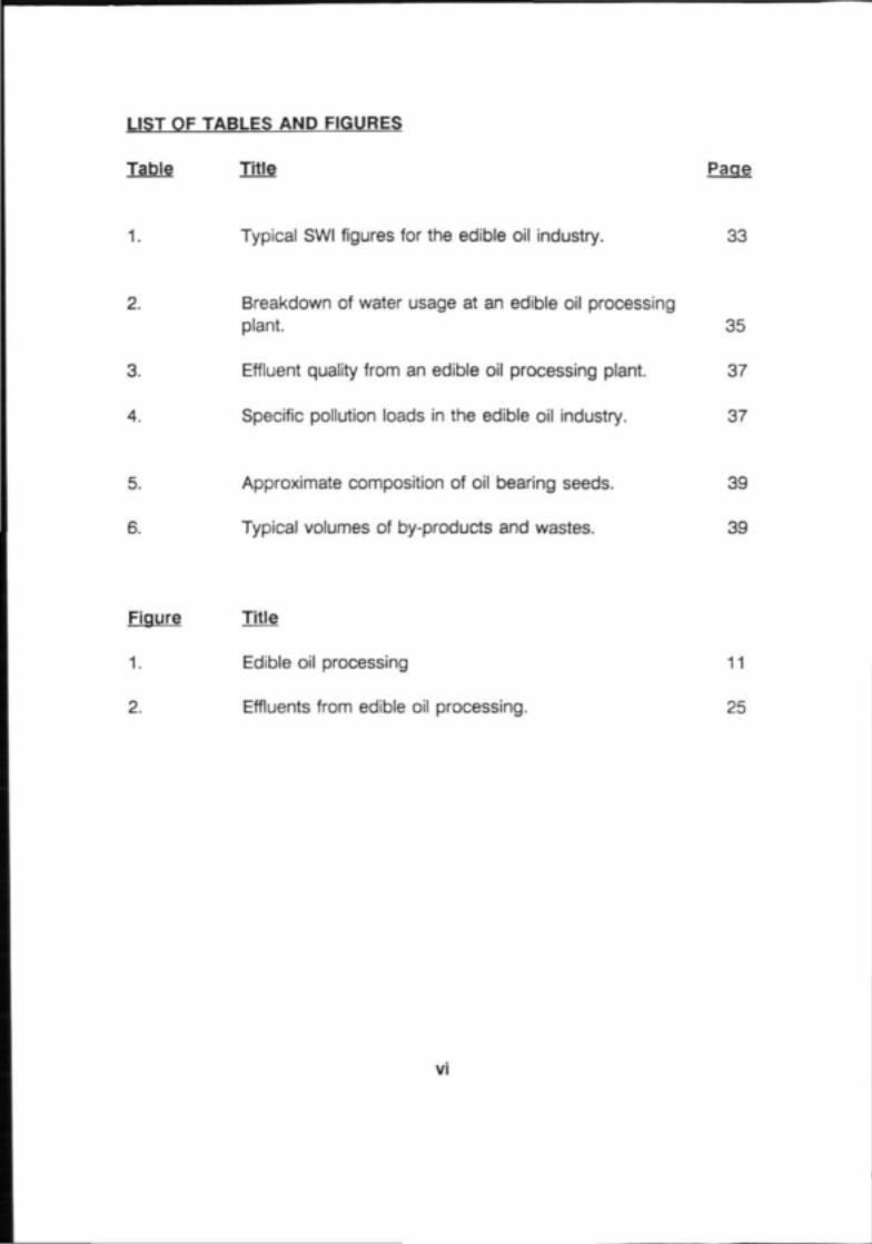
LIST OF TABLES AND FIGURES
Table Title Page
1. Typical SWI figures for the edible oil industry. 33
2. Breakdown of water usage at an edible oil processing
plant. 35
3. Effluent quality from an edible oil processing plant. 37
4. Specific pollution loads in the edible oil industry. 37
5. Approximate composition of oil bearing seeds. 39
6. Typical volumes of by-products and wastes. 39
Figure Title
1. Edible oil processing 11
2. Effluents from edible oil processing. 25
VI

4 SUMMARY OF SURVEY RESULTS 33
4.1 Water intake 33
4.2 Effluent 36
4.3 Solid wastes and by-products 38
5 CONCLUSIONS AND RECOMMENDATIONS 40
5.1 Water intake 40
5.2 Effluent 42
5.3 Effluent treatment 43
5.4 Storm water 48
6 REFERENCES 50

TABLE OF CONTENTS Page
1 INTRODUCTION 1
2 PROCESS RESUME 3
2.1 Background 3
2.2 Crude oil production 5
2.3 Oil Processing 8
2.4 Chemical refining 13
2.5 Physical refining 18
2.6 Packaging 20
3 BY-PRODUCTS, WASTES AND EFFLUENTS 23
3.1 Seed preparation 23
3.2 Oil extraction 23
3.3 Degumming 26
3.4 Chemical refining 26
3.5 Physical refining 30
3.6 Margarine 30
3.7 Washdown 31
3.8 Miscellaneous effluents 31
IV

SUMMARY
There are 16 edible oil processing plants in South Africa, producing approximate-ly 250 000 t of edible oil annually. The industry consumes approximately 1,5million cubic metres of water each year.
Specific water intakes (SWI) were found to range between 2,1 and 3,1 m3/t formilling and 3,2 and 4,6 m3/t for refining. Improvements in SWI can be achievedby improved water management. Target SWI figures of 2,0 m7t for milling and3,0 m3/t for refining are proposed. A target of 5,0 m3/t for a plant milling andrefining all product oil on-site is proposed.
Specific pollution loads (SPL) were found to range between 4,3 and 13,8 kg ofCOD/t oil, and 10,1 and 24,8 kg TDS/t oil. Targets of 7 kg COD/t oil, and 12kg TDS/t oil would seem to be reasonably achievable by the industry. Againthese targets apply to a plant milling and refining all product oil on-site.
in

ACKNOWLEDGEMENTS
The preparation of this publication was constituted under the leadership of thefollowing Editorial Committee:
DR 0 0 HART (Chairman) Water Research CommissionMR DF SUTTON Department of Water AffairsMR CM OLIVIER Nola IndustriesMR JAC COWAN Steffen, Robertson and KirstenMR P SKIVINGTON Steffen, Robertson and Kirsten
Their contributions and that by Mr AJ Elphinston, are gratefully acknowledged.

FOREWORD
The need for guidelines to reduce water intake and waste-water disposal byindustry is of national concern in view of South Africa's water scarcity.
To establish norms for water intake and waste-water disposal, the WaterResearch Commission (WRC) in collaboration with the Department of WaterAffairs (DWA) contracted Steffen, Robertson and Kirsten, a firm of consultingengineers, to undertake a National Industrial Water and Waste-water Survey(NATSURV) of all classes of industry.
The consultants identified 75 industrial groupings in South Africa, one of whichis the edible oil industry. The results obtained in the survey of the edible oilindustry form the basis of this guide on Water and Waste-water Managementin the Edible Oil Industry.
It is expected that this Guide will be of value to the industry itself and to otherinterested parties such as municipalities, administrators, researchers andconsultants in the water and effluent fields.

ABBREVIATIONS
AOF - Acid oil factor
CIP - Cleaning-in-place
COD - Chemical oxygen demand
DAF - Dissolved air flotation
FFA - Free fatty acids
OA - Oxygen absorbed
SEV - Specific effluent volume
SOG - Soaps, oils, greases
SPL - Specific pollution load
SS - Suspended solids
SWI - Specific water intake
TDS - Total dissolved solids
xiii

INTRODUCTION
The edible oil industry consumes approximately 1,75 million m3 of water
each year. The total quantity of oi! refined in South Africa has remained
relatively constant over the last few years, at approximately 250 000 t/a
but is expected to increase by about 3% per annum over the next few
years. Good maize crops and a record oil seed production of 982 000
t enabled the industry to produce a record 275 000 t of oil in 1981.6 The
continuing drought since that year, however, has resulted in a dramatic
decline in locally produced oil, and in the year 1985/86 only about 150
000 t of oil was produced from local raw material. The balance of
approximately 100 000 t oil was imported, mostly in crude form, to be
refined in South African refineries. Since then improved rains have led to
an increase in the proportion of locally produced oil with production for
the 1988-89 season being about 240 000 t/a, of which 30 000 to 35 000
t/a was imported.
There are two clearly defined stages in the production of refined vegetable
oil - crude oi! production conducted in an oil mill, and oil processing
conducted in a refinery. In South Africa the two stages of the process are
usually conducted on the same site although marine oils and animal fats,
where used , are purchased as such.
An oil plant typically discharges about 35% of the incoming water to
sewer. The remaining 65% is either vapourised in the many cooling
circuits, or else leaves the site in one of a number of secondary products
and by-products. The effluent that is discharged to sewer will contain

quantities of fat, oil, sodium, sulphates, phosphates and other pollutants.
The effluent thus has a high inorganic as well as a high organic loading.
Municipal treatment works have to treat the majority of this effluent.
There are 16 edible oil plants in South Africa, run by a total of 10 separate
groups. This guide presents data collected from eleven oil plants and
concludes with several recommendations aimed at reducing both water
usage by and pollution load from an oil processing plant.

PROCESS RESUME
2.1 Background
The principal product of an edible oil refinery is liquid oil which
may be sold as cooking or salad oil or may be further processed
to increase the market value of the product. Common examples
of this are the manufacture of margarine, cooking and bakers' fat,
peanut butter and mayonnaise.
Vegetable oil may be obtained from a wide variety of seeds,
including cotton seed, soya bean, peanuts, sunflower seed,
maize, rice bran, palm kernels, linseed, olives and coconut. The
varying climatic conditions found around the world favour the
cultivation of different oil bearing seed and as a result of this, the
seed from which oil is extracted varies with geographic location.
North America's primary oil seed crops are cotton seed and soya
bean, whilst the Far East's oil is extracted primarily from palm,
palm kernel and coconut sources. In South Africa the most
commonly grown oil bearing crops are sunflower, groundnut and
maize, although other seeds, such as cotton and soya, are also
processed. In addition to these vegetable oils, a large quantity of
both locally-produced and imported fish oil and some animal fat
is also refined.
The situation is further complicated by the fact that different
hybrids of a particular oil seed thrive in different parts of the

world. Thus, sunflower seed from North America may require
different processing steps than locally harvested sunflower seed.
The drought which South Africa has experienced over the last few
years has meant that insufficient seed has been available locally
to meet oil demands, and the shortfall has had to be made up
with imports from elsewhere around the world. These imports
may be in the form of seed or more usually unrefined or semi-
refined (degummed and neutralised) oil. Recent better rains have,
however, meant that a much larger proportion of the oil produced
in South Africa has been derived from local seed. For the 1988-
89 season only about 15% of the oil produced has been derived
from imported, unrefined or semi-refined oil, compared to 26% in
1986.
Another important factor to consider is that the edible oil industry
in South Africa utilises only about 65% of its processing capacity
at present. This has an important bearing on the efficiency of
water use by the industry as will be discussed later.
There are two distinct stages involved in the production of
vegetable oil: separation of the oil from the oil-bearing seed and
subsequent refining of this oil. Although final product oil from
each of the many sources has similar properties, each seed type
has process requirements peculiar to itself- The fundamental unit
processes in the recovery of the oil and its subsequent refining
are, however, similar for each oil type. These unit processes are
described below and attention is drawn to the various individual

requirements of each oil type.
2.2 Crude oil production
2.2.1 Seed preparation
When seed arrives at an oil mill, the first operation is the
removal of all foreign matter, such as sticks, stones and
metal articles. This is usually achieved by the use of
magnets, bar screens, sieves and air separators. The
cleaned seed is now ready for the next process stage.
2.2.2 Sunflower and soya
These seeds are first decorticated after which the meats
are separated from the hulls using vibratory screens and
air lifts. The hulls are removed to ensure that the protein
content of the resulting meal meets prescribed stand-
ards.
The separated meats, made up of small, tough walled
cells containing the oil, may be rolled into thin flakes to
make them more permeable to steam in the ensuing
cooking step. Here the flakes are subjected to live
steam and brought up to a predetermined optimum
temperature and moisture content. Conditioned seed
from the cookers is passed to screw presses (expellors)
where about 75% of the oil is squeezed from the flakes.

small fraction of this expelled oil, containing fines, may
be mixed with the incoming conditioned meats, whilst the
remainder is filtered and sent to storage.
The expelled meat or cake still contains approximately
25% of its oil content, and this is extracted using a
solvent extraction process. The cake is washed with
hexane leaving about 1% oil in the final meal. This is
usually effected using a counter-current system in which
an oil rich miscella is contacted with fresh oil cake, whilst
fresh hexane contacts with outgoing cake. The dis-
charged cake loses about 95% of its entrained hexane
in a vapour desolventiser and the remainder of the
solvent is removed from the cake using live steam
injection. The vapours flow to scrubbers where
entrained fines are removed and recycled to the extract-
or. Solvent-free meal is removed and cooled.
Miscella from the extractor is pumped to a rising film
evaporator for primary separation of oil and solvent. The
enriched miscella from the evaporator now flows to a
steam-heated oil stripper where hexane is recovered
from the oil with live superheated steam. The recovered
oil is cooled and pumped to storage.
The evaporator and oil stripper are both equipped with
condensers that liquify the solvent vapours. Hexane

leaving the stripper condenser contains water that was
injected as live steam into the stripper; this stream goes
to a water separator where make-up hexane is added.
Vapours from the evaporator condenser, the desolven-
tiser condenser and the separating tank go to a com-
mon vent condenser where they are cooled with water.
To prevent hexane losses, gases from the vent conden-
ser are washed with mineral oil in an absorber. Water
vapour and non-condensables are vented to atmosphere
from this vessel and the rich mineral oil is pumped to a
stripper where hexane is flashed, condensed and
recycled.
2.2.3 Maize germ
In the extraction of oil from maize germ, the expelling
stage associated with high oil content seeds such as
sunflower is not always used. Instead, conditioned germ
is fed directly to a solvent extraction plant.
2.2.4 Cotton seed
The preparation of cotton seed prior to oil extraction is
more difficult than for the seeds mentioned above, since
the remaining cotton lint must first be removed from the
seeds before conditioning can take place. Once this
step has been performed, however, the oil is extracted

in a very similar manner to that described for sunflower
and soya.
2.2.5 Developments
Innovations are constantly implemented in this industry,
and one of the more recent of these is direct expelling
of non-conditioned seed. Screw presses are now
available which develop sufficient heat through friction to
effectively condition the seed and expel the oil in a single
unit process.
2.3 Oil processing
The crude oil is composed largely of glycendes of various
saturated and unsaturated fatty acids, notably oleic and linoleic
acids. There are, however, a number of impurities which must be
removed from the oil before it can be considered fit for human
consumption. These impurities vary according to the particular
type of oil, the geographic location of the source, the season, the
way in which the oil has been stored and prepared and the
manner in which the oil has been extracted. These impurities can
be classified into four broad categories,
(a) Gums
A collective term referring to phosphatides, sugars, resins and
other proteinaceous material. The gum content of sunflower.
8

maize and soya is of the order of 2%, while cotton seed can be
even higher.10'12
(b) Free fatty acids
These can occur in extremely high quantities (as high as 40%
sometimes) but usually range between 0,5% and 8%, depending
on the oil type.10
(c) Pigment
Usually of chlorophyllic or carotenic base. Cotton oil in particular
has a deep red-black colouration associated with gossypol.
(d) Taste and odour
Chiefly a result of volatile aldehydes and ketones.
Crude oil is refined to remove this objectionable content. There
are two approaches to refining and both are in wide commercial
use. The classic method of refining a crude oil is neutralisation
with caustic soda followed by bleaching and deodorising of the
neutralised oil. Study of the deodorising step in this "chemical"
method led to the introduction of what is known as "physical"
refining.
Attention has already been drawn to the fact that the constituents
and properties of oils depend upon their source. These differen-
ces in composition necessitate the use of slightly different
processing techniques. Nonetheless, the stages in the two
principal methods of oil refining are illustrated in Figure 1. The
essential operating features of each of these stages is described
briefly below.
2.3.1 Crude oil storage
Refining can be said to start in the crude oil storage tank,
since oil-insoluble matter separates here by gravity.
Semi-solid oils are maintained at slightly elevated tempera-
tures.
10

Figure 1 Edible oil processing
Crude oiI storage
"Chemical"Refining
Degum
"Physical" Refining
Neutralise Bleach
Bleach
Uinterise Hydrogenate
Neutratise
Bleach
Blend
Deodori se Steam strip
Packing
11

2.3.2 Degumming
Gums may be broadly separated into hydratable and
non-hydratable types. Their removal is important on at
least three counts:
(a) their emulsifying properties, which increase losses during
chemical refining;
(b) their tendency, on heating to deodorising temperatures,
to impart deep brown colouring to finished oil; and
(c) their tendency to form complex compounds with certain
trace metals which adversely affect product stability.
Hydratable gums (usually amounting to between 60 and 75%
of the total gum content) are comparatively simply removed
by the addition of hot water and subsequent separation of the
swoiien, insoluble gums in centrifuge equipment.10 £ Removal
of non-hydratable gums requires prior treatment with phos-
phoric or citric acid to render them hydratable."' The
subsequent removal of the now hydrated gums may either be
achieved by the addition of a small amount of water followed
by centrifugation or by use of an activated absorbent coupled
with a filter. Many variations on this two stage process are
used, including combining the two operations into one.
12

2.4 Chemical refining
2.4.1 Neutralisation
As mentioned above, crude oil naturally contains a percen-
tage of free fatty acids (FFA) - carboxylic acids which have
been separated by natural degradation from the
triglycerides. In the chemical refining process these acids
are neutralised by the addition of caustic soda. Caustic
soda up to 4N strength16 is intimately mixed with the oil at
a predetermined optimum temperature in either batch,
semi-continuous or continuous equipment. A strong
caustic solution such as is used in this step will tend to
saponify the neutral triglycerides with consequent loss of
neutral oil, and thus careful control of the operating
conditions is required. Certain oils are particularly suscep-
tible to saponification, and in these cases a more dilute
caustic solution is used.
Besides saponifying the FFA in the crude oil, the addition
of caustic provides a much more effective hydration of
gums than the simple addition of water. It is therefore
sometimes possible to dispense with a separate degumm-
ing step for oils with low gum contents. To a certain extent
caustic will also affect pigments and this provides a
valuable method of recovering poorer quality and more
highly coloured oils, such as cottonseed oil.
13

In continuous and semi-continuous equipment the
immiscible soap (termed "soapstock") produced upon
neutralisation is separated from the neutralised oil using
centrifuges. In batch operation, gravitational settling and
subsequent separation is used. Soapstock is usually
further treated on-site to produce acid oil.
2.4.2 Bleaching
In addition to colour removal, bleaching acts as a further
"purification" step in the refining process.
This step in the refining process is conducted under
vacuum at raised temperatures and may again be per-
formed in batch, semi-continuous or continuous equipment.
Bleaching clay (up to 2% by weight) is introduced, the
clay/oil mix agitated, and filtered.13'1416 Sometimes the clay
is added in two stages: an unactivated clay first absorbs
soap while a more expensive activated clay absorbs trace
metals, pigments and various oxidation products which
would otherwise cause severely reduced product life.
2.4.3 Hydrogenation
Oil which is intended for use in margarine and other similar
products must be hydrogenated: this produces fats with
superior keeping qualities as well as higher melting points.
14

The process consists of dispersing hydrogen gas in oil in
the presence of a catalyst. The catalyst most widely used
is finely divided nickel supported on a diatomaceous earth.
In order to prevent poisoning of this catalyst, oil to be
hydrogenated must first be neutralised and bleached,
ensuring the oil is dry and clean.
In the reaction, hydrogen is added at the points of
unsaturation in the fatty acid chain. Naturally occurring oils
contain fatty acids having up to six double bonds in the
chain: hydrogenation attempts to saturate these selectively,
reducing the six double bonds to five, the five to four, and
so on.
Although some continuous plants are in use, most hydro-
genation is carried out in batch equipment. An evacuated
autoclave is charged with oil and heated to the required
temperature. Catalyst is added and hydrogen is fed to the
reactor where it is continuously mixed with the circulating
oil. Hydrogenation is an exothermic reaction. If the
temperature were to be allowed to rise uncontrolled the oil
would undergo undesirable side reactions; consequently
the temperature is controlled using cooling circuits. When
hydrogenation has proceeded to the desired end point, the
oil is cooled from the reaction temperature of approximately
185°C and is filtered to separate the catalyst from the
product.
15

When hardened oil is produced in this manner, the oil
suffers an increase in free fatty acid content which must
again be reduced. In addition, filtration is not able to
eliminate completely all traces of nickel from the hydro-
genated oil. Both of these impurities are usually removed
by a subsequent caustic neutralisation/bleach step, known
as "post-neutralising" and "post-bleach". Hydrogenation
also imports a characteristic flavouring to the product, so
that hardened or hydrogenated oil must be deodorised in
the same way as other oil.
2.4.4 Winterising
Certain vegetable oils, including sunflower and maize,
contain wax from the seed shell or husk, and this causes
an undesirable cloudy appearance at lower temperatures,
when they begin to crystallise. Typically, wax content
varies between 200 and 2 000 mg/kg, and this must be
reduced to 10 mg/kg if adequate cold stability is to be
obtained.12 This reduction is effected by careful cooling of
the oil to approximately 5°C, followed by filtration to remove
the crystallised wax. This process, known as winterising, is
usually only performed on oil which is to be marketed as
such. It is not necessary to winterise oil which is to be
hydrogenated. After winterising the oil is usually
deodorised.
16
2.4.5 Deodorising
All refined and bleached oil goes through a deodortsation
step, although oil intended for use in margarine is hydro-
genated first and other oil may be winterised beforehand if
necessary.
Basically, the deodorisation process involves steam distilla-
tion under vacuum. Its purpose is to remove, so far as is
possible, residual free fatty acids, aldehydes and ketones
(which are responsible for unacceptable odours and
flavours) and decolourising final oil by thermal decomposi-
tion of the pigments. The decomposition products from
the pigments are subsequently distilled off.
Once again batch, semi-continuous or continuous plant
may be employed, each having its own advantages under
particular circumstances. In a typical semi-continuous
deodorising unit, partially heated oil is fed to a top tray or
tank where air and other volatile materials are released
from the oil under full vacuum. In a second tank an
indirect heat exchange medium, such as Dowtherm, is
used to heat the oil to the operating temperature of
between 18OCC and 250cC before the bulk of the total of
4% open steam is injected for deodorisation/ s = The
deodorised oil is now cooled in lower tanks before being
17

pumped to storage. Small quantities of citric acid may be
injected during the cooling stages to retard oxidation of the
2.5 Physical refining
In the deodorisation process open steam, heat and very low
pressure are used to remove small quantities (approximately
0,15%) of fatty acids and other impurities from the oil. The basis
of physical refining (or steam stripping) is the use of deodorisers
for the steam distillation of all the free fatty acids as well as
odoriferous volatiles without a prior neutralising stage. The
physical refining technique has two primary advantages over the
conventional caustic refining route: reduction in oil loss and the
elimination of soapstock and its associated effluent treatment
problem.
As was mentioned in the description of the caustic refining
neutralisation step, quantities of neutral oil are saponified together
with the free fatty acids. This saponified oil is then separated with
the soapstock and forms a significant loss of product oil. One of
the values used to measure the efficiency of the refining process
is the acid oil factor (AOF), defined as the percentage of acid oil
by-product recovered from the soapstock divided by the percen-
18

tage of free fatty acid in the crude oil. A value of 1,0 is perfection
and standard caustic refining, as described earlier, range from 1,3
for easily refined oils to 4 for low FFA oils in batch units. Physical
refining provides factors of about 1,2 for all oils and is capable of
handling oils having an FFA content of 8% and above - which
would be very difficult using the traditional caustic process.16
One very important requirement, however, is that the feedstock
should be rigorously pretreated to ensure that it is free from
phosphatides, impurities, trace metals and earth-removable
pigments. If these impurities were to be allowed to remain in the
oil, the high temperatures used in the process would darken the
oil and cause a poor quality product. The extent of the
pretreatment necessary is dependent on the particular oil and its
quality; the criteria most often used are the percentage content of
non- hydratable gums and of iron and the oxidative state of the
feedstock.
Pretreatment of high FFA oils such as maize and sunflower prior
to physical refining, typically comprises the addition of phosphoric
or citric acid at temperatures of approximately 70°C followed by
high speed centrifugation to remove the hydrated gums. The
centrifuged oil is dried and subsequently bleached and winterised
before being sent to the physical refining section. Here the oil is
pumped into a vacuum deaerator before entering the top heating
section of the stripper. In this section the oil is heated to a
temperature of up to 270°C using a thermal fluid (such as
19
Dowtherm) from a vapouriser. In a continuous unit the oil is then
refined by flowing over the top series of trays counter-current to
the fiow of stripping steam which is injected below the bottom
tray. The "refined" oil now flows down to a holding section which
provides the retention necessary for heat bleaching of some of
the oils before a final series of trays enables steam stripping of all
remaining odoriferous material.
Exiting oil transfers some of its heat to the incoming feed before
being pumped to polishing filters and on to storage.
Semi-continuous units are also frequently used for physical
refining and these operate on the same basic principles as the
continuous unit described above.
2.6 Packaging
The term packaging, as used in vegetable oil processing, differs
somewhat from that usually employed in industry in that it
includes not only final product packing but also the preparation
for that step. The most important product from the packaging
area of a vegetable oil processing plant is margarine, although
other oil based products such as mayonnaise, peanut butter or
shortening may also be produced on the same site.
2.6.1 Margarine
Margarine is a water-in-oil emulsion, consisting of a
20
continuous oil phase and a discontinuous aqueous phase
finely dispersed in the oil phase; the oil phase contains fat
crystals which give the margarine its body. Legislation
dictates that the minimum oil content of a margarine is 80%
and the maximum water content is 16%. Flavouring,
colouring, emulsifiers and various vitamins (particularly A
and D) are amongst the ingredients added to the oil phase,
whilst salt and milk solids are contained in the aqueous
phase.
The margarine industry has become extremely competitive
in recent years and this has resulted in a wide variety of
different formulations being prepared, some of these
contain up to 40% aqueous phase - although these are no
longer strictly "margarines" but fat "spreads". Various
consumer preferences have resulted in, for instance, the
development of salt free margarines, as well as margarines
with a high polyunsaturated fatty acid content; other
margarines are required to have good spreadability straight
from a refrigerator. Each of these specifications require a
carefully selected blend of various vegetable oils and fats.
Margarine manufacture can be performed as either a batch
or a continuous operation. The two phases each have the
various ingredients added to them before being intimately
mixed to form an emulsion. This emulsion is then chilled
in a unit known as a "votator" - a rotating drum whose
21
inner surface is kept cold by circulating refrigerant. Rows
of scraper blades remove the crystallised emulsion from
the chilled surface and pass on to a resting tube (the
"B-unit") where the remaining latent heat of crystallisation is
released and the product solidifies.
From the B-unit the margarine is fed to the packaging
machine where the product is wrapped in blocks or packed
in tubs. The finished product is stored in refrigerated
warehouses prior to despatch.
22
BY-PRODUCTS, WASTES AND EFFLUENTS
3.1 Seed preparation
The principal by-product from this operation is the husk or hulls
from which the oil bearing seed has been removed. These hulls
are frequently added to animal feeds to provide fibre and
roughage. Only a limited amount can be used in this way,
however, since legislation restricts fibre content in standard feeds.
Any surplus hulls are usually transported to the boiler house
where they are used as a supplementary fuel.
3.2 Oil extraction
Regardless of whether oil is expelled or extracted using a solvent,
this operation produces a large quantity of defatted meal.
Residual oil content in the meal after desolventising is of the order
of 0,5% with a moisture content below 10%; protein content is of
the order of 40%.5" This meal may be toasted to increase its
nutritional value and then removed for use in animal feeds.
Legislation and storage requirements dictate a maximum moisture
content allowable in the meal.
The relatively complex system utilised to recover and recycle
hexane in the solvent extraction process gives rise to small
volumes of aqueous effluent. This effluent is primarily from
condensed stripping steam and scrubbers used to prevent fines
23

from entering the recovered solvent cycle. Blow-down from
cooling towers serving the solvent extraction process probably
produces a more significant volume of effluent.
24

Figure 2 Effluents from edible oil processing
Crude OiI storage
CHEMICALREFINING
Oegum gumsPHYSICALREFINING
Neutralise
Bleach
waxes& fat
winterise
FFA S,Odoursetc
Deodorise
soapstock& soapy water
spent earth
Bleach
Hydrogenate
Neutralise
Bleach
Blend
• cataLystin clay
-••soapstock& soapywater
-•spentearth
spentearth
Steam strip -•FFA &odours
Packaging
25

3.3 Degumming
The gums separated from the crude oil prior to either chemical or
physical refining invariably contain small quantities of oil. The
gums themselves consist primarily of complex lipids, so that the
mixture of gum and oil is highly nutritious. For this reason the
extracted gums are usually mixed with the defatted meal for
subsequent processing into animal feeds. Any citric acid intro-
duced to facilitate degumming serves as a preservative in the
animal feed.
Alternatively, it is possible to dry the gums in a thin film evapor-
ator and process them to derive commercial lecithin products.
3.4 Chemical refining
3.4.1 Neutralisation
Chemical refining with caustic soda gives rise to the most
potent effluent generated at an oil processing plant. In the
neutralisation process, free fatty acids present in the crude
oil are removed as highly alkaline soapstock. A quantity of
neutral crude oil is also saponified in this process, the
exact percentage (indicated by the acid oil factor) being
determined by the oil type and neutralising procedure.
This soapstock is usually converted back into fatty acids
using a strong acid, either as a batch or a continuous
26

process. The product of this operation is known as acid
oil, which is used in the manufacture of paints, varnishes
etc. The process, variously described as acidulation,
soapstock conversion or soap splitting, consists of three
basic steps:
(a) acidification of the highly basic soapstock, usually
with sulphuric acid;
(b) breaking the emulsion of fatty acid and foreign
material in water by means of heat (often live steam
injection), pressure and agitation; and
(c) separation of the phases.
The presence of gums in the soapstock tends to favour
the formation of an emulsion, so that, where no prior
degumming stage is employed in conjunction with chemi-
cal refining, the resultant soapstock is difficult to split.610
The aqueous phase from the splitting operation is ap-
proximately pH 2, and after some has been recycled to
dilute incoming soapstock, the remainder must be
neutralised by the addition of caustic soda. The resultant
neutralised liquid, predominantly a sodium sulphate
solution, is discharged to drain.
After the separation of soapstock from the neutralised oil,
the oil must be washed to remove all traces of caustic.
27

This is performed using water which is intimately mixed
with the oil before being separated either continuously in a
centrifuge, or gravitationally. Sometimes the resultant
effluent stream, known as soapy water, is discharged to
drain after neutralisation. However this results in the loss
of valuable oil and contributes a large percentage of the
pollution load in the final effluent. For these reasons.
soapy water is often mixed with the soapstock already
removed from the oil, forming an homogenous mixture
from which acid oil is more easily recovered in the soap
splitting operation.6
3.4.2 Bleaching
The majority of the pigment contained in the crude oil
being refined is absorbed onto activated clays during
bleaching. When removed, this clay contains a certain
amount of oil as well as any remaining soap that was not
washed out after neutralisation. Used bleaching earth is
usually removed from the oil refinery in a skip before being
dumped.
3.4.3 Winterising
Oil temperature is reduced to approximately 5=C causing
high melting point esters and waxes to crystallise. These
fat crystals are subsequently removed in a filter, usually
28

with the assistance of diatomaceous earth as a filter aid.
The fat/earth mixture is removed and discarded with the
bleaching clay.
3.4.4 Hydrogenation
Nickel catalyst, mixed with diatomaceous earth, is
removed from hydrogenated oil in a filter. This sludge is
collected to enable subsequent recovery of the nickel.
Wastes from the post-neutralisation and post-bleach steps
are handled in the same way as their equivalents in the
primary neutralisation and bleaching.
3.4.5 Deodorising
The deodorisation process involves steam distillation at
pressures of approximately 5 mm Hg; injected steam
constitutes up to 4% of oil weight. Vacuum in the
deodorising unit is maintained by means of three stage
steam- jet ejectors.
The distillate from the oil contains the volatile compounds
responsible for the oil's characteristic odour as well as any
remaining FFA. The vacuum pulls these vapours together
with the stripping steam through a scrubber where the bulk
of the FFA and any entrained oil are recovered. The
stripping steam and remaining FFA vapours now mix with
29

the motive steam from the ejectors to form a single stream
which is condensed using direct contact cooling water.
The volume of water in the cooling circuit is thus aug-
mented by the condensed steam, and after collection in a
hot well, the water is recycled over cooling towers and
returned to the steam ejector condensers. Excessive build-
up of FFA in the circuit is avoided by regular removal of
floating fats in a sump just prior to the cooling towers.
These fats may be recovered subsequently as acid oil. It
is usually possible to balance evaporation and blowdown
losses from the cooling circuit with the condensed steam
being added, so that only minimal quantities of make-up
are necessary.
3.5 Physical refining
Except for the higher temperatures involved, physical refining can
be considered to be approximately analogous to the deodorising
step used in chemical refining. Therefore the side streams
produced are generally handled in the same way as those from
the deodoriser.
3.6 Margarine
Incorrectly packed or off-specification margarine is usually
recycled to recover and reprocess the oil content. Damaged
packaging materials are removed for incineration or dumping.
30

The major source of effluent from this section is washdown water.
3.7 Washdown
Most of the plant used in an edible oil refinery must undergo
regular cleaning. This will generally be performed after a week's
production or between changes in feedstock; batch equipment
may be cleaned after each batch has been processed.
Cleaning of vessels is usually effected using live steam and hot
water on a CIP system, thus ensuring optimum use of steam,
reduction in effluent volume, improved hygiene and reduced
manual labour. Other cleaning, such as floor cleaning, is
conducted using hot water as necessary. This fat and oil bearing
effluent is discharged to the sewer via fat traps, where the oil rich
scum is recovered and sent for reworking.
3.8 Miscellaneous effluents
The bulk of the remaining effluent, in terms of volume, emanates
from the boiler house. The high steam demand of the industry
requires considerable volumes of softened water, and this in turn
gives rise to large volumes of regeneration effluent flowing to
drain from ion exchange water softening units.
Return of condensate from the various vessels in the oil process-
ing plant is often no more than 20%, since the risk of oil contami-
31

nation is considered to outweigh any possible water savings.
Nevertheless, regular biowdown of the boiler contents is necess-
ary to regulate build-up of salts in the water.
These streams combine with cooling tower biowdown to form a
significant volume of comparatively saline effluent.
32

4 SUMMARY OF SURVEY RESULTS
4.1 Water intake
The results obtained from the survey are shown in tabular form in
Table 1.
Table 1 Typical SWI figures for the edible oil industry
Mi I I ing
Refining
Average monthly
oiI production (t)
Range Mean
1 000 - 3 600 2 080
1 000 - 3 600 2 520
Average monthly3
water intake (m )
Range Mean
2 070 - 11 070 5 390
3 100 - 16 600 9 650
Spec i f i c
water intake (m /t)
Range Weighted
average
2,1-3,1 2,6
3,2-4,6 3,8
It must be noted that almost every plant producing edible oil also
produces secondary products such as margarine, peanut butter and
mayonnaise. The figures quoted in Table 1 refer specifically to oil milling
and refining. An average SWI of 1,4 m3/t was found for the manufacture
of margarine.
From Table 1 the weighted average SWI was found to be 2,6 m3/t for
milling and 3,8 m3/t for refining. It is important to consider that for the
33

edible oil industry in general, only about 65% of capacity is currently being
utilised. This is of significance because many plant operations require the
same amount of water to be used regardless of the plant throughput at
the time. This will obviously lead to higher SWI figures when plants are
operating at below design capacity. It is expected that recent better rains
may result in an increase in utilisation of capacity by the edible oil industry
in South Africa over the next few years. Size of plant is not really an
important issue for the edible oil industry as plants are all of similar size.
This is a different situation from that in, for example, the red meat industry
where there is a tremendous variation in plant size and capacity.
The variation in SWi was found to be 2,1 to 3,1 m3/t for milling and 3,2
to 4,6 m3/t for refining. This is a clear indication that opportunities for
better water management do exist within the industry.
The SWI for a combined mill and refinery is implied to be 6,4 nV/t from
addition of the individual SWI figures for milling and refining. This agrees
well with the SWI figures typically found for a combined mill and refinery
though certain economies of scale would tend to result in slightly lower
SWI figures for the combined plant.
4.1.1. Breakdown of water use
Table 2 below indicates how water is used in a typical edible oil plant.
Since much of the steam used in the refinery is motive steam for steam-jet
ejector sets, this water enters the barometric cooling circuit and is
ultimately lost to evaporation. It could therefore be argued that the
34

cooling requirement of the refinery exceeds the figure of 10% quoted in
the table.
Table 2 Breakdown of water usage at an edible oil processing plant
ProcessBoilersCoolingWashdownDomestic
Hill
X
2102511
39
Refinery(including
hydrogenation)
13301071
61
Total
15403582
100
Utilities are by far the largest water users in an edible oil plant with boilers
typically accounting for 40% and cooling 35% of the water intake at an oil
mill/refinery.
Condensate return is low with typically only about 20% of the available
condensate to the hot well. The remaining condensate is either contamin-
ated or potentially contaminated and as such is discharged as effluent.
Live steam use is quite considerable and again this is obviously lost to the
system as is steam used in steam ejectors. These can represent up to
10% and 20% respectively of the total steam use in an edible oil plant.
Steam raising and cooling water use varies seasonally.
The figures include water used for preparing husks and hulls for use in
subsequent products, but do not include the preparation of these
products themselves. The figures exclude all operations not directly
associated with the production of vegetable oil, such as the manufacture
of margarine, peanut butter and mayonnaise.
35

4.2 Effluent
When considering effluent from various oil mills, there are several points
which should be considered:
(a) Whether finished oil is produced from seed or whether the factory
only produces crude oil or only refines purchased oil.
(b) Whether the predominant refining method is chemical or physical.
This will be governed both by type of feedstock and by installed
plant.
(c) Whether other products such as margarine, peanut butter and
mayonnaise are manufactured on the site.
(d) Whether the existing effluent drainage system allows representative
sampling of individual process effluents. The tendency of free fats
to float on the surface of aqueous effluents increases the difficulty
of obtaining representative samples.
(e) Whether any form of effluent treatment is practised prior to final
discharge.
4.2.1 Specific pollution load
Edible oil plants discharge an effluent which varies considerably in
quality over a 24-h period. Composite samples of final effluent were
collected and the results summarised in Table 3 below:
36

Table 3 Effluent quality from an edible oil processing plant
Average monthlyeffluentdischarge
(mi )
Range2 180 - 8 200
Mean5 130
PH
Range1,8 - 10,5
Mean5,9
CODCmg/L)
Range1100 - 8990
Mean4 580
D E T E F
SOG(mg/l)
Range80 - 1360
Mean630
M I N A N D
TDSCmg/l)
Range1910 - 17550
Mean4 860
soA2~
(mg/l)
Range130 - 10 950
Mean1 805
Table 4 Specific pollution loads in the edible oil industry
Average monthlyeffluentdiscbarge(m3)
Range2 180 - 8 200
Mean5 130
Average monthlyoiI production
(t)
Range1 000 - 3 600
Mean2 520
SPECIFIC POLLUTION LOAD
COD(kg/t)
Range4,3 - 13,
Mean9,8
SOG(kg/t)
Range0,2 - 3,3
Mean1,6
TDS(kg/t)
Range10,1 - 24,8
Mean15,4
SO 2-
(kg/t)
Range2,1 - 15,5
Mean7,6
As it is normally impossible to distinguish effluents arising from the
mill and refinery in an edible oil plant, the final effluent analyses are
given and the SPL figures are based on the total tonnage of refined
oil produced monthly.
From Tables 3 and 4 it can be calculated that the mean SEV is
2,0 m3/t. This gives an average percentage effluent discharge of
31%.
From the average pollutant concentrations calculated in Table 4, the
following average SPL figures have been calculated:
Average COD = 9,8 kg/t
Average SOG = 1,6 kg/t
Average TDS = 15,4 kg/t
37

Average sulphate = 7,6 kg/t
4.2.2 Breakdown of specific pollution load
In terms of volume and load the largest proportion of the effluent
discharged by an edible oil plant arises from refining operations.
Typically about 80% of the effluent volume is attributable to the
refinery.
The main sources of effluent in the mill are general washing and as
a result of hexane recovery. In the refinery, effluents can be discha-
rged from the degumming stage (gums), the neutralisation stage
(soapstock and soapy water) and the bleaching stage (spent earth),
as well as the various steam and cooling operations and general
washing.
The main types of pollutant in edible oil plant effluents are fats and
oils. Foiiowing neutralisation of the crude oii and subsequent soap
splitting, water is used for washing, giving rise to effluents known as
soapy water and acid water. These can contain considerable
quantities of fats and oils and contain very high levels of sodium and
sulphate. Detergents used in washdown operations often emulsify
oils leading to high levels of oils in the plant effluent which are very
difficult to remove.
4.3 Solid wastes and by-products
The production of large quantities of solids is unavoidable when extracting
38
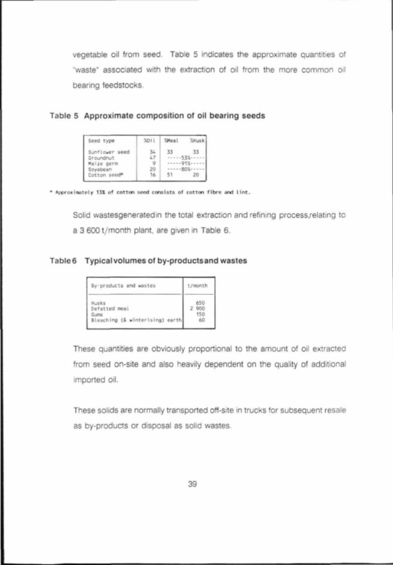
vegetable oil from seed. Table 5 indicates the approximate quantities of
"waste" associated with the extraction of oil from the more common oil
bearing feedstocks.
Table 5 Approximate composition of oil bearing seeds
Seed type
Sunflower seedGroundnutMaize germSoyabeanCotton seed*
XOil
344792016
%Heal %Husk
33 3353%91%80%
51 20
* Approximately 13X of cotton seed consists of cotton fibre and lint.
Solid wastesgeneratedin the total extraction and refining process.relating to
a 3 600 t/month plant, are given in Table 6.
Table6 Typicalvolumes ot by-productsand wastes
By-products and wastes
HusksDefatted mealGumsBleaching (& winterising) earth
t/month
6502 90015060
These quantities are obviously proportional to the amount of oil extracted
from seed on-site and also heavily dependent on the quality of additional
imported oil.
These solids are normally transported off-site in trucks for subsequent resale
as by-products or disposal as solid wastes.
39

CONCLUSION AND RECOMMENDATIONS
5.1 Water intake
Edible oil plants in South Africa have a range of SWI between 2.1
and 3,1 m3/t for milling and 3,2 and 4,6 m3/t for refining.
The varying properties of crude oil as extracted from different seeds,
have a strong bearing on the type of processing steps required and
this in turn will affect the necessary water intake. Thus it is very
difficult to set a realistically achievable SWI for the industry as a
whole. Nonetheless, target figures of 2.0 nr/ t for milling and 3.0
mJ/t for refining would seem to be realistically achievable for the
industry as a whole. These figures imply a target SWI of 5,0 m3/t for
a plant milling raw seed and refining the crude oil produced without
any additional crude oil being introduced from another source. Due
to recent better rainfall this is increasingly the typical case and
particularly if plants begin to utilise more of their design capacity,
5,0 m3/t should be a readily achievable target.
Since some 75% of water intake to an oil processing plant is used
in services, it is logical that the greater potential for saving should lie
within the services. Several methods of reducing water intake are
listed below:
(a) ensure maximum condensate return possible to boiler
house: the use of carbon filters should be considered to
enable the reuse of water which may contain minute
40

quantities of oil;
(b) ensure cooling towers are working efficiently - allow for
regular cleaning of oil-clogged packing and other internals;
(c) monitor automatic blowdown from cooling towers and
boilers to avoid excessive blowdown losses;
(d) the use of boiler blowdown for moistening coal ash;
(e) consideration should be given to treating blowdown in a
reverse osmosis unit to render it suitable for reuse in the
boiler;
(f) use of high pressure, low volume equipment for floor
washing and other general washdown requirements (each
should be fitted with a self closing nozzle device);
(g) greater use of CIP installations for pipes, tanks and
centrifuges;
(h) installation and control of water meters at all sections in the
operation and commitment from the factory management
to a water monitoring and management programme;
(i) improved staff training to increase awareness of water
saving methods;
(j) shut down of pump gland cooling water lines on pumps
when not in use1;
(k) substitute air cooling for some water cooling requirements
where feasible1; and
(I) investigate operation of cooling towers on a zero-blowdown
basis which has been reported1 as being successful on a
pilot plant basis following the addition of a chromate
corrosion inhibition.
41

5.2 Effluent
The range of SPLs for edible oil plants in South Africa is 4,3 to 13,8 kg
COD/t oil and 10,1 to 24,8 kg TDS/t oil. Targets are proposed of 7 kg
COD/t oil and 12 kg TDS/t oil.
Primary pollutants from an oil plant are fats and oils, with an associated
oxygen demand. In addition, where acid oil is recovered from soapstock,
very high concentrations of Na~ and SO/ occur.
Since the presence of fat and oil in the effluent constitutes loss of marketable
oil, it is in the interest of the management to reduce the fat content to a
minimum. Methods of achieving this are presented below:
(a) monitor caustic addition in the neutralisation stage of chemical
refining very carefully as excess caustic causes saponification of
neutral oil and later problems with removal as soapstock;
(b) ensure soapstock separation from neutral oil is performed accura-
tely;
(c) use continuous soap splitting plant in preference to batch wherever
possible: resultant acid water can be greatly reduced in this way:=
(d) ensure soap splitting operation is conducted on fresh soapstock:
soapstock is split more effectively if treated immediately than if left
to stand overnight prior to reheating and acid addition;2
(e) use as little detergent as possible in cleaning operations: emulsified
oil cannot be removed from the resultant effluent very easily;
(f) removal of gums prior to neutralisation: their presence in soapstock
42

hinders the efficiency of the acid splitting operation;20
(g) fat traps should be placed wherever washdown water is likely to
contain oil or fat: recovered fat can be sent for reworking or acid oil
recovery;
(h) use of a flume or similar monitoring equipment to measure effluent
discharge accurately, since this is otherwise difficult to estimate;
(i) use of acid water from soap splitting operation for subsequent acid
splitting of final effluent.
(j) replacement of barometric condensers with surface (non-contact)
condensers which will reduce emulsified oil pick-up in barometric
condenser water2;
(k) recirculation of oily cooling water produced by barometric conden-
sers in a separate cooling system with occasional blowdown ; and
(I) replacement of steam-jet ejectors by vacuum pumps, eliminating the
production of oily condensate by the jet ejectors'.
5.3 Effluent treatment
Effective treatment of refinery effluent may be achieved by a combination of
screening, acid splitting of oil emulsions, skimming of fats and oils and final
neutralisation.
5.3.1 Screening
Gross solids, such as defatted meal and husks, which may have
entered the effluent system may be removed using a rotary, vibrating
or a static "self- cleaning" screen. Both would need periodic
43

cleaning, preferably with live steam jets.
5.3.2 Acidification
The bulk of the fatty matter contained in soapy water, deodoriser
effluent and final effluent is in an emulsified form. This content,
together with any colloidal or dissolved fat, will not be removed by
the direct application of gravity separation techniques. Destabilisa-
tion of these emulsions can be achieved using sulphuric acid, and
this has the advantage that the separated fatty material can be
recovered. Where prior soap splitting has been performed, the acid
water generated may be used for this purpose, with fresh acid being
used on a standby basis only. Fatty matter released in this way may
now be removed in a gravity settler system.
At sites where effluent streams exist which do not contain emulsified
fatty substances, these streams should be segregated from the
others and only mixed with the acidified stream after the de-emuls-
ified oil has been separated. This will necessitate the use of two
flotation stages, one for the acidified stream and one for the
combined stream.
5.3.3 Gravity separation
Since fats and oils are less dense than water, the simplest way of
separating these pollutants from oily effluent is flotation.
44

In its simplest form, a flotation system may consist of a tank contai-
ning a series of baffles beneath which the aqueous phase can flow
freely. A manometric arm maintains the liquid level at baffle height
so that fatty material is trapped; periodically fat has to be removed
manually from the surface. This fat can often be reprocessed.
As mentioned above, gravity separation will not remove fats or oils
in emulsion form. The effectiveness of a gravity separator depends
on the water temperature, the density and size of the oil globules
and the amount and characteristics of the suspended matter in the
waste water1. It must be remembered that provision should be made
for periodic removal of sludge from the separator vessels. It is
important to realise the limitations of gravity separators in edible oil
plant waste-water treatment. These are:
(a) they can only remove gravity-separable oils and will not
separate stable emulsions;
(b) other parameters only undergo limited reduction;
(c) any emulsifier, spent caustic or detergent present will tend
to reduce efficiency of removal;
(d) suspended solids attached to oils may not settle; and
(e) hydraulic overloading reduces efficiency.
5.3.4 Dissolved air flotation (DAF)
An alternative or subsequent treatment stage to gravity separation
45

is dissolved air flotation in which air is dissolved in the effluent in a
pressure vessel before the solution is released into an open flotation
tank. The sudden reduction in pressure causes the air to leave
solution as very fine bubbles which then adhere to any oil, fat or
other suspended solids in the effluent and bring them to the surface.
The entrained air causes the resulting agglomerates to have greatly
improved vertical rise rates, typically1 0,0025 to 0,005 m/s.
The layer of frothy solids, fats and oils which forms is swept into an
inclined exit chute by a rotating arm or other skimming device.
Typical design parameters for dissolved air flotation units would be1:
Pressure 170 to 480 kPa
Air/solids ratio 0,01 to 0,1
Retention time 20 to 60 min
Surface hydraulic
loading 2 to 330 m3/m2.d
Solids loading 2,4 to 24,0 kg/m'.h
Polyelectrolyte addition usually enhances fat and oil removal from
waste waters. Fatty material in food industry effluent is normally
negatively charged and treatment therefore involves the addition of
an ion of the opposite charge to destabilise the emulsion3. Comm-
46

only used agents for breaking emulsions include ferric chloric,
sodium aluminate, aluminium sulphate, ferrous sulphate and lime.
5.3.5 Neutralisation
Effluent from the first, low pH separation will need neutralising with
caustic soda before being mixed with the remaining effluent and
being subjected to a final flotation process. The liquor discharged
from this second flotation unit must be neutralised to bring the pH
value up to local statutory requirements. This final neutralisation can
be effected with either caustic soda or calcium hydroxide. Calcium
hydroxide addition would avoid a further increase in the sodium
content of the final discharge, but would give rise to a siudge
handling problem requiring the use of a filter, probably a plate and
frame type. Although requiring an additional stage of treatment, the
filtration process would provide further removal of fatty matter, COD
and suspended solids.
5.3.6 Biological treatment
5.3.6.1 Aerobic
A strain of bacteria has been developed which will digest fats from
this type of effluent, and at least one oil plant in South Africa runs an
activated sludge treatment facility as a polishing unit to complement
a DAF system. Problems encountered in the running of such a plant
stem from periodic shock loads of, for instance, soapstock spillages.
47

5.3.6.2 Anaerobic
Anaerobic treatment of readily biodegradable effluents, particularly
from the food and beverage industry, is receiving much attention
worldwide at this time. Research work is being conducted in
Malaysia on the applicability of the technology to the treatment of
vegetable oil mill effluent.4 Palm oil mill effluent, such as was the
subject of this research, is of a very different nature from effluents
generated in local oil plants. Nonetheless, anaerobic treatment of
effluent should be investigated especially when other highly biodegr-
adable effluents are available from nearby sources.
5.3.7 Membrane technology
Reverse osmosis making use of ultra-thin synthetic or natural
membranes may be viable for treating process effluent high in TDS
such as acid water. This is particularly true in areas where strict
standards are enforced regarding, for example, sulphate content,
where edible oil plants are presently tankering effluents high in
sulphate off their premises for disposal elsewhere.
5.4 Storm water
Storm water run-off from an oil refinery site invariably contains quantities of
fats and oils. Provision should therefore be made for preventing this oil from
entering the storm-water drains. A combination of two approaches can be
used:
(a) storm water from potentially heavily polluted areas, such as tank
48

farm bunded areas, should be directed to the effluent treatment
plant; and
(b) all other storm water should pass through fat traps before being
discharged to municipal storm-water drains.
49

6 REFERENCES
1. Barnes, D., Forster, C.F. and Hrudey.S.E.,"Surveys in Industrial Waste-Water
Treatment", Vol.2, "Petroleum and Organic Chemicals lndustries"Pitman
(1984).
2. Binnie and Partners (Queensland), "Report on Effluent Treatment and
Disposal for PTL Margarines and Oils", No. C108 (1981).
3. Binnie and Partners, "Physical/Chemical Treatment", Report prepared for
Water Research Commission, No. 174 (1985).
4. Chin, K.K. and Wong, K.K., "Palm Oil Refinery Wastes Treatment", WAT RES,
15, 1087-1092 (1981).
5. Chin, K.K. and Wong, K.K., "Thermophilic Anaerobic Digestion of Palm Oil
Effluent", WAT RES, 17, 993-995 (1983).
6. Cofield, E.P., "Solvent Extraction of Oil Seed", CHEM ENG, 58, (1), 127-140
(1951).
7. Crauer, L.S., "Continuous Recovery of Acid Oil", J AM OIL CHEM SOC, 42,
(7), 661-663 (1965).
8. Dudrow, FA , " Deodorization of Edible Oil",J AM OIL CHEM SOC, 60, (2),
224A-226A (1983).
50

9. Editorial comment, J AM OIL CHEM SOC, 63, (8), 966-67 (1986).
10. Forster, A. and Harper, A.J., "Physical Refining", J AM OIL CHEM SOC, 60
(2), 217A-223A (1983).
11. Frampton, G.A., "Equipment Selection for Vegetable Oil Refineries", CHEM
& PROC ENG, 50, (2), 91-96 (1969).
12. Haines, W.H., Perry, G.C. and Gastrock, E.A., "Filtration-Extraction of
Cottonseed Oil", IND & ENG CHEM, 49, (6), 920-929 (1957).
13. Haraldsson, G., "Degumming, Dewaxing and Refining", J AM OIL CHEM
SOC 60, (2), 203A-208A (1983).
14. Hightower, J.V.,"Better Way to Bleach Vegetable Oils", CHEM ENG, 56, (9),
102-104 (1949).
15. Sanders, J.H.,"Processing of Food Fats - A Review", FOOD TECH, 13, (1),
41-45 (1959).
16. Wurster, O.H., " Hydrogenation of Fats", IND & ENG CHEM 32, (9), 1193-
1199 (1940).
51