water distiller service manual - statimusa.com
TRANSCRIPT

Water DistillerService Manual
L70478WT ©2008RegalWare,Inc.
Water D
istiller Service Man
ual

Table of Contents
- 1 -
RECOMMENDED TOOLS...................................................................................................................... 2
GENERAL INSPECTION ..........................................................................................................................3
BOILING CHAMBER TROUBLESHOOTING & REPAIRS
Description....................................................................................................................................................... 4
Primary boiler components....................................................................................................................... 4
Boiling chamber inspection & electrical service
Replacing boiling chamber connector.......................................................................................... 5
Red light does not come on .............................................................................................................. 5
Checking for electrical continuity ................................................................................................... 6
Replacing control board ..................................................................................................................... 7
Short cycle - unit stops running prematurely............................................................................. 7
Replacing boiler thermostat.............................................................................................................. 8
Long cycle or boiler not heating...................................................................................................... 9
CHASSIS TROUBLESHOOTING & REPAIRS
Chassis electric system description...................................................................................................... 10
Chassis tubing system description....................................................................................................... 10
Primary chassis components .................................................................................................................. 10
Chassis inspection & electrical service
Fan blade inspection and repair.................................................................................................... 11
Condensing coil thermostat inspection and repair ............................................................... 12
Fan motor inspection and repair/replacement........................................................................ 12
Chassis tubing inspection and repair .......................................................................................... 14
Replacing steam spout ..................................................................................................................... 15
Replacing chassis connector........................................................................................................... 16

Recommended Tools
- 2 -
A Hammer
B 3⁄16 inch wrench
C 1⁄4 inch wrench
D Flat head/straight edgescrewdriver
E Needle nose pliers
F Wire cutter/stripper
G Ohmmeter
H Wire crimpers (not pictured)
A
B C D E F G
General Inspection
- 3 -
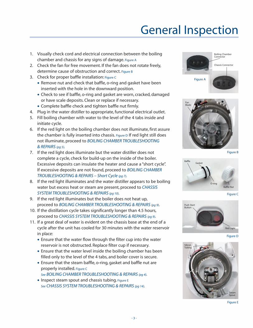
1. Visually check cord and electrical connection between the boilingchamber and chassis for any signs of damage. Figure A
2. Check the fan for free movement. If the fan does not rotate freely,determine cause of obstruction and correct. Figure B
3. Check for proper baffle installation: Figure C
• Remove nut and check that baffle, o-ring and gasket have beeninserted with the hole in the downward position.
• Check to see if baffle, o-ring and gasket are worn, cracked, damagedor have scale deposits. Clean or replace if necessary.
• Complete baffle check and tighten baffle nut firmly.4. Plug in the water distiller to appropriate, functional electrical outlet.5. Fill boiling chamber with water to the level of the 4 tabs inside and
initiate cycle.6. If the red light on the boiling chamber does not illuminate, first assure
the chamber is fully inserted into chassis. Figure D If red light still doesnot illuminate, proceed to BOILING CHAMBER TROUBLESHOOTING & REPAIRS (pg 5).
7. If the red light does illuminate but the water distiller does notcomplete a cycle, check for build-up on the inside of the boiler.Excessive deposits can insulate the heater and cause a “short cycle”.If excessive deposits are not found, proceed to BOILING CHAMBERTROUBLESHOOTING & REPAIRS – Short Cycle (pg 7).
8. If the red light illuminates and the water distiller appears to be boilingwater but excess heat or steam are present, proceed to CHASSISSYSTEM TROUBLESHOOTING & REPAIRS (pg 10).
9. If the red light illuminates but the boiler does not heat up,proceed to BOILING CHAMBER TROUBLESHOOTING & REPAIRS (pg 9).
10. If the distillation cycle takes significantly longer than 4.5 hours,proceed to CHASSIS SYSTEM TROUBLESHOOTING & REPAIRS (pg 9).
11. If a great deal of water is evident on the chassis base at the end of acycle after the unit has cooled for 30 minutes with the water reservoirin place:
• Ensure that the water flow through the filter cup into the waterreservoir is not obstructed. Replace filter cup if necessary.
• Ensure that the water level inside the boiling chamber has beenfilled only to the level of the 4 tabs, and boiler cover is secure.
• Ensure that the steam baffle, o-ring, gasket and baffle nut areproperly installed. Figure C
See BOILING CHAMBER TROUBLESHOOTING & REPAIRS (pg 4).
• Inspect steam spout and chassis tubing. Figure E
See CHASSIS SYSTEM TROUBLESHOOTING & REPAIRS (pg 14).
Figure A
Figure C
Figure D
Figure E
Figure B
Boiling ChamberConnector
Chassis Connector
Fan Blade
Baffle
Baffle Nut
O-ring
Gasket
Push StartButton
Red Light
Silicon Tubing
SteamSpout
DESCRIPTIONThe boiling chamber consists of a water vessel, a heating unit, a thermostat, a control circuit board, asocket and various leads and connectors. When the start button is depressed, a relay on the control circuitboard closes the power circuit to the heating circuit. A red indicator lamp attached to the control circuitboard illuminates to verify start-up. The heating unit provides the heat to boil the water in the vessel. Asthe water volume in the boiling chamber is reduced, the thermostat, which is wired in series to the heaterunit, senses the increased boiler temperature and opens the circuit to the heater. Any power interruptionto the water distiller or the boiler will open the relay circuit and discontinue the cycle. To resume the cycleafter power interruption, the start button must be depressed to close the relay circuit.
NOTE: Before opening the boiler for inspection, try inserting it into another water distiller that is knownto function properly. If the boiler then functions properly the fault is related to the chassis.See CHASSIS SYSTEM TROUBLESHOOTING & REPAIRS (pg 10).
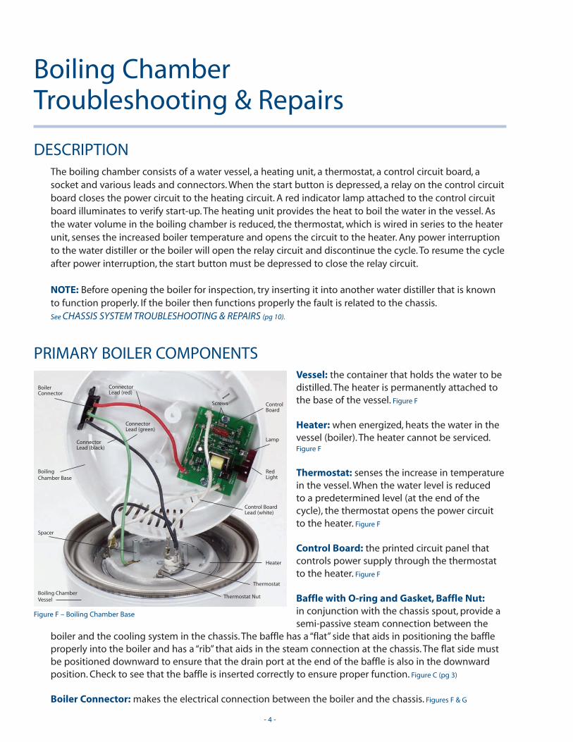
PRIMARY BOILER COMPONENTSVessel: the container that holds the water to bedistilled. The heater is permanently attached tothe base of the vessel. Figure F
Heater: when energized, heats the water in thevessel (boiler). The heater cannot be serviced.Figure F
Thermostat: senses the increase in temperaturein the vessel. When the water level is reduced to a predetermined level (at the end of thecycle), the thermostat opens the power circuit to the heater. Figure F
Control Board: the printed circuit panel thatcontrols power supply through the thermostatto the heater. Figure F
Baffle with O-ring and Gasket, Baffle Nut:in conjunction with the chassis spout, provide asemi-passive steam connection between the
boiler and the cooling system in the chassis. The baffle has a “flat” side that aids in positioning the baffleproperly into the boiler and has a “rib” that aids in the steam connection at the chassis. The flat side mustbe positioned downward to ensure that the drain port at the end of the baffle is also in the downwardposition. Check to see that the baffle is inserted correctly to ensure proper function. Figure C (pg 3)
Boiler Connector: makes the electrical connection between the boiler and the chassis. Figures F & G
Boiling Chamber Troubleshooting & Repairs
- 4 -
Figure F – Boiling Chamber Base
BoilingChamber Base
BoilerConnector
RedLight
ConnectorLead (red)
ConnectorLead (green)
ConnectorLead (black)
Lamp
ControlBoard
Control BoardLead (white)
Screws
Boiling ChamberVessel
Heater
Thermostat
Thermostat Nut
Spacer
- 5 -
BOILING CHAMBER INSPECTION & ELECTRICAL SERVICE
Replacing Boiling Chamber Connector
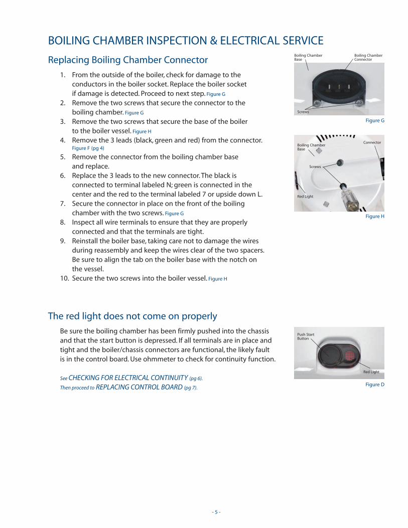
1. From the outside of the boiler, check for damage to theconductors in the boiler socket. Replace the boiler socket if damage is detected. Proceed to next step. Figure G
2. Remove the two screws that secure the connector to the boiling chamber. Figure G
3. Remove the two screws that secure the base of the boiler to the boiler vessel. Figure H
4. Remove the 3 leads (black, green and red) from the connector.Figure F (pg 4)
5. Remove the connector from the boiling chamber base and replace.
6. Replace the 3 leads to the new connector. The black is connected to terminal labeled N; green is connected in the center and the red to the terminal labeled 7 or upside down L.
7. Secure the connector in place on the front of the boiling chamber with the two screws. Figure G
8. Inspect all wire terminals to ensure that they are properlyconnected and that the terminals are tight.
9. Reinstall the boiler base, taking care not to damage the wiresduring reassembly and keep the wires clear of the two spacers.Be sure to align the tab on the boiler base with the notch on the vessel.
10. Secure the two screws into the boiler vessel. Figure H
The red light does not come on properly
Be sure the boiling chamber has been firmly pushed into the chassisand that the start button is depressed. If all terminals are in place andtight and the boiler/chassis connectors are functional, the likely faultis in the control board. Use ohmmeter to check for continuity function.
See CHECKING FOR ELECTRICAL CONTINUITY (pg 6).
Then proceed to REPLACING CONTROL BOARD (pg 7).
Figure G
Boiling ChamberConnector
Screws
Boiling ChamberBase
Figure H
Connector
Red Light
Screws
Boiling ChamberBase
Figure D
Push StartButton
Red Light
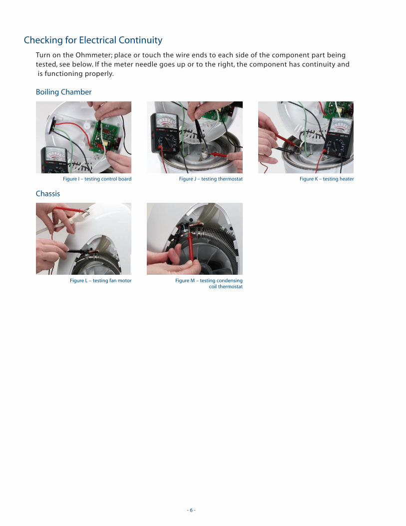
Checking for Electrical Continuity
Turn on the Ohmmeter; place or touch the wire ends to each side of the component part beingtested, see below. If the meter needle goes up or to the right, the component has continuity andis functioning properly.
Boiling Chamber
Chassis
- 6 -
Figure I – testing control board Figure J – testing thermostat Figure K – testing heater
Figure L – testing fan motor Figure M – testing condensing coil thermostat
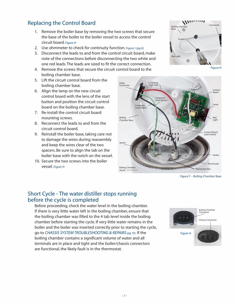
Replacing the Control Board
1. Remove the boiler base by removing the two screws that secure the base of the boiler to the boiler vessel to access the control circuit board. Figure H
2. Use ohmmeter to check for continuity function. Figure I (pg 6)
3. Disconnect the leads to and from the control circuit board, make note of the connections before disconnecting the two white and one red leads. The leads are sized to fit the correct connection.
4. Remove the screws that secure the circuit control board to theboiling chamber base.
5. Lift the circuit control board from theboiling chamber base.
6. Align the lamp on the new circuitcontrol board with the lens of the startbutton and position the circuit controlboard on the boiling chamber base.
7. Re-install the control circuit board mounting screws.
8. Reconnect the leads to and from thecircuit control board.
9. Reinstall the boiler base, taking care not to damage the wires during reassemblyand keep the wires clear of the twospacers. Be sure to align the tab on theboiler base with the notch on the vessel.
10. Secure the two screws into the boilervessel. Figure H
Short Cycle - The water distiller stops running before the cycle is completed
Before proceeding, check the water level in the boiling chamber.If there is very little water left in the boiling chamber, ensure that the boiling chamber was filled to the 4 tab level inside the boilingchamber before starting the cycle. If very little water remains in theboiler and the boiler was inserted correctly prior to starting the cycle,go to CHASSIS SYSTEM TROUBLESHOOTING & REPAIRS (pg 10). If theboiling chamber contains a significant volume of water and allterminals are in place and tight and the boiler/chassis connectors are functional, the likely fault is in the thermostat.
- 7 -
Figure H
Connector
Red Light
Screws
Boiling ChamberBase
Figure F – Boiling Chamber Base
BoilingChamber Base
BoilerConnector
RedLight
ConnectorLead (red)
ConnectorLead (green)
ConnectorLead (black)
Lamp
ControlBoard
Control BoardLead (white)
Screws
Boiling ChamberVessel
Heater
Thermostat
Thermostat Nut
Spacer
Figure A
Boiling ChamberConnector
Chassis Connector
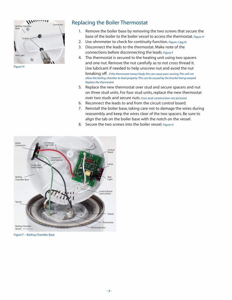
Replacing the Boiler Thermostat
1. Remove the boiler base by removing the two screws that secure the base of the boiler to the boiler vessel to access the thermostat. Figure H
2. Use ohmmeter to check for continuity function. Figure J (pg 6)
3. Disconnect the leads to the thermostat. Make note of the connections before disconnecting the leads. Figure F
4. The thermostat is secured to the heating unit using two spacers and one nut. Remove the nut carefully as to not cross thread it.Use lubricant if needed to help unscrew nut and avoid the nut breaking off. If the thermostat moves freely this can cause poor sensing.This will not
allow the boiling chamber to heat properly. This can be caused by the bracket being warped.
Replace the thermostat.
5. Replace the new thermostat over stud and secure spacers and nuton three stud units. For four stud units, replace the new thermostatover two studs and secure nuts. Four stud construction not pictured.
6. Reconnect the leads to and from the circuit control board.7. Reinstall the boiler base, taking care not to damage the wires during
reassembly and keep the wires clear of the two spacers. Be sure toalign the tab on the boiler base with the notch on the vessel.
8. Secure the two screws into the boiler vessel. Figure H
- 8 -
Figure H
Connector
Red Light
Screws
Boiling ChamberBase
Figure F – Boiling Chamber Base
BoilingChamber Base
BoilerConnector
RedLight
ConnectorLead (red)
ConnectorLead (green)
ConnectorLead (black)
Lamp
ControlBoard
Control BoardLead (white)
Screws
Boiling ChamberVessel
Heater
Thermostat
Thermostat Nut
Spacer

The water distiller’s cycle is much longer than 4.5 hours; or, the red light illuminates but the boiler isn’t heating
Before proceeding, ensure that the boiler is the proper voltage.Improper voltage (240 volt heater with 110 volt power supply or vise versa) the water distiller will produce at a greatly reduced rate.The voltage is indicated on the heater unit. If the boiler is of thecorrect voltage, the heater unit may be at fault.
1. Remove the boiler base by removing the two screws that securethe base of the boiler to the boiler vessel to access the heater.Figure H
2. Use ohmmeter to check for continuity function. Figure K (pg 6)
3. The heater unit is not field-serviceable. If the heater unit does notshow continuity, the complete boiling chamber or the boilervessel (service part available) must be replaced.
4. The boiler vessel for the 120V/240V includes the heater and 2 spacers. Figure F (pg 8)
5. Using the existing boiling chamber base, reconnect the components.
6. Reconnect the circuit control board white leads to the thermostat and heater.
7. Reconnect the connector leads. Black lead connects to thethermostat. The green lead is connected under the single spaceropposite the thermostat.
8. Reinstall the boiler base, taking care not to damage the wiresduring reassembly and keep the wires clear of the two spacers.Be sure to align the tab on the boiler base with the notch on the vessel.
9. Secure the two screws into the boiler vessel. Figure H
- 9 -
Figure D
Push StartButton
Red Light
Figure H
Connector
Red Light
Screws
Boiling ChamberBase

CHASSIS ELECTRICAL SYSTEM DESCRIPTIONThe chassis system consists of the cooling fan, the condensing coil, the condensing coil thermostat, themain power supply socket, the boiler electrical connector, the steam spout, vapor and water tubes, thewater exit elbow, and various electrical leads and connectors. The main electrical supply system providespower from the household supply to the boiling chamber and the electric cooling fan. The steam spoutprovides the vapor connection between the boiling chamber and the vapor tubing. The vapor tubingroutes the steam into the condensing coil. When the condensing coil reaches a specified temperature thecondensing coil thermostat closes the power circuit to the fan motor. The fan supplies a flow of air pastthe condensing coil. The cooling process condenses the vapor back to its liquid state. The distilled water isrouted from the condensing coil to the water jug through the water tube and the water exit elbow.
CHASSIS TUBING SYSTEM DESCRIPTIONSteam generated in the boiling chamber must be cooled to a liquid state, passed through the filter cupand then delivered to the water jug. The chassis tubing system incorporates a steam spout to make theconnection between the boiler and the chassis. A silicon tube carries the steam into the condenser wherethe steam is cooled to a liquid state. The distilled water exits the condenser and is carried by gravitythrough another silicon tube to the exit elbow. From the exit elbow, the highly distilled water drips intothe water jug.
PRIMARY CHASSISCOMPONENTSChassis Connector: distributes electrical supplyfrom power cord to all of the electricalcomponents in the unitand makes the electricalconnection between thechassis and the boilingchamber via the boilingchamber socket. Figure N
Condenser: is a heat exchanger that transfers the heat from the steam, causing the steam tocondense into its liquid state, distilled water.The condenser is comprised of a stainless steeltube with aluminum cooling fins. Figure O
Fan: consists of a motor and a fan rotor.Aids the condensation process by moving
Chassis SystemTroubleshooting & Repairs
- 10 -
Figure O – Chassis without Vent Cover
Condensing CoilThermostat Clip
CondensingCoilCondensing Coil
Thermostat Lead
SiliconTubing
FanBlade
Screws
Hood
Motor
Figure N – Chassis Connector
ChassisHousing
ChassisConnector
ChassisBase
Condensing CoilThermostat

a moderate volume of air through the condenser.The fan motor is fittedwith an internal thermal fuse. Figure O
Condenser Thermostat: is an energy saving feature. It senses heat in thecondenser and then closes the electrical circuit to the fan motor. Figure O
Steam Spout: in conjunction with the boiler baffle, makes the semi-passive steam connection between the boiler and the chassis. Figure P
Silicon Tubing: is of very high purity and very high durability.Two lengths of silicon tubing are used to transportsteam to the condenser and transport cooled waterfrom the condenser to the water jug. NOTE: The sectionof silicon tubing that connects the steam spout to thecondenser has a very small port drilled through it atone of its ends. This is a feature called a “volatile gasvent” and is intended to improve the water quality.When replacing the tubing, be sure that the vent isvisible. The vented end of the tubing is to be connectedto the condenser and the vent should be positioned tothe top of the tubing. Figure Q
Exit Elbow: is the small white elbow from which thedistilled water flows into the water jug. The exit elbowis connected by a section of silicon tubing to thecondenser. Figure Q
NOTE: Unless otherwise specified, unplug the water distiller from the power supplybefore proceeding.
CHASSIS INSPECTION & ELECTRICAL SERVICE Check for damage at the chassis connector and power cord; replace if necessary.See REPLACING THE CHASSIS CONNECTOR ( pg 16).
Fan Blade Inspection and Repair
1. Remove the top vent cover. Figure R
• Locate the “notch” at the back of the cover.
• Insert a screwdriver. (Be careful not to damage the finish.)
• Pry the back of the vent cover upward.
• Pull the vent cover free from the chassis hood.2. Verify free movement of the fan blade. Figure O (pg 10)
3. Inspect the fan blade for fractures or other damage.4. Replace fan blade, if necessary, by pulling fan blade
upward with both hands.5. Place replacement fan blade over motor shaft and
snap into place.
- 11 -
Figure P
Steam Spout
Figure Q – Chassis without Hood & Fan Blade
CondensingCoil
Condensing CoilThermostat Lead
SiliconTubing
Steam Spout
Ribbed ChassisHousing Screws
Fan Motor
Motor Wires
Condensing CoilThermostat
Fan MotorScrews
Silicon Tubingwith VOC Vent
Exit Elbow
Figure R
Notch
Chassis Vent Cover
Chassis Hood
Locking Tab
WireClip
Condensing CoilThermostat Clip
Fan Motor Inspection andRepair/Replacement
1. Remove the top vent cover. Figure R (pg 11)
• Locate the “notch” at back of cover.
• Insert screw driver. (Be careful not to
damage the finish.)
• Pry the back of the vent cover upward.
• Pull the vent cover free from the chassis hood.
2. Use ohmmeter to check for fan motor continuity function. Figure L (pg 6)
3. Remove the fan blade by pulling fan blade upward with hands. Figure S
4. Check that the fan motor rotor movesfreely. If there is resistance to movement,the fuse has likely opened and the fuseneeds to be reset or the motor replaced.
5. The fuse on the motor is resetable byplacing the boiling chamber into thechassis and pushing the red start button.Figure D (pg 9)
6. If this does not reset the motor, it will need to be replaced.7. Remove the black screw on the backside of the unit that secures the
hood to the chassis body Figure T and the two screws holding thefront of the hood. Figure S Remove hood.
- 12 -
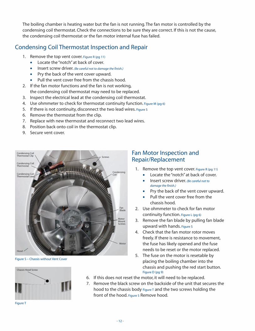
Figure S – Chassis without Vent Cover
CondensingCoil
FanBlade
Screws
Hood
Motor
MotorMountScrews
Figure T
Chassis Hood Screw
The boiling chamber is heating water but the fan is not running. The fan motor is controlled by thecondensing coil thermostat. Check the connections to be sure they are correct. If this is not the cause,the condensing coil thermostat or the fan motor internal fuse has failed.
Condensing Coil Thermostat Inspection and Repair
1. Remove the top vent cover. Figure R (pg 11)
• Locate the “notch” at back of cover.
• Insert screw driver. (Be careful not to damage the finish.)
• Pry the back of the vent cover upward.
• Pull the vent cover free from the chassis hood.2. If the fan motor functions and the fan is not working,
the condensing coil thermostat may need to be replaced.3. Inspect the electrical lead at the condensing coil thermostat.4. Use ohmmeter to check for thermostat continuity function. Figure M (pg 6)
5. If there is not continuity, disconnect the two lead wires. Figure S
6. Remove the thermostat from the clip.7. Replace with new thermostat and reconnect two lead wires.8. Position back onto coil in the thermostat clip.9. Secure vent cover.
Condensing CoilThermostat Clip
Condensing CoilThermostat Lead
Condensing CoilThermostat
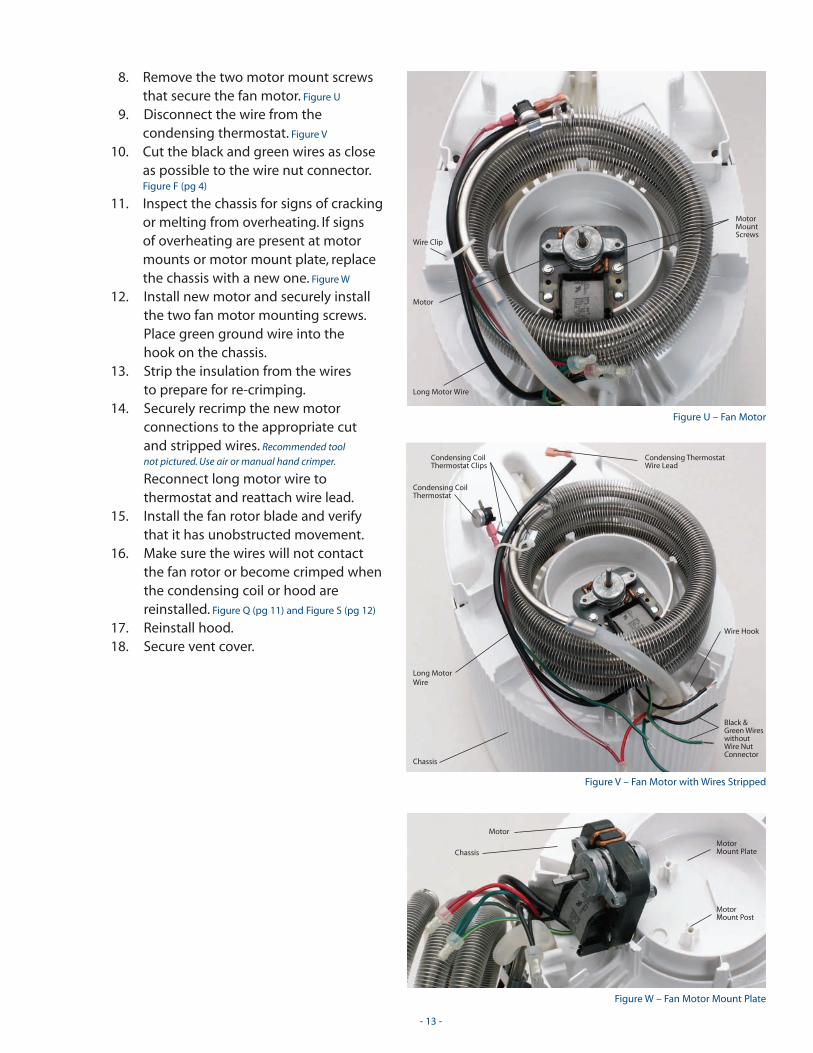
8. Remove the two motor mount screwsthat secure the fan motor. Figure U
9. Disconnect the wire from thecondensing thermostat. Figure V
10. Cut the black and green wires as closeas possible to the wire nut connector.Figure F (pg 4)
11. Inspect the chassis for signs of crackingor melting from overheating. If signs of overheating are present at motormounts or motor mount plate, replacethe chassis with a new one. Figure W
12. Install new motor and securely installthe two fan motor mounting screws.Place green ground wire into the hook on the chassis.
13. Strip the insulation from the wires to prepare for re-crimping.
14. Securely recrimp the new motorconnections to the appropriate cut and stripped wires. Recommended tool
not pictured. Use air or manual hand crimper.
Reconnect long motor wire tothermostat and reattach wire lead.
15. Install the fan rotor blade and verifythat it has unobstructed movement.
16. Make sure the wires will not contactthe fan rotor or become crimped whenthe condensing coil or hood are reinstalled. Figure Q (pg 11) and Figure S (pg 12)
17. Reinstall hood.18. Secure vent cover.
- 13 -
Figure U – Fan Motor
Long Motor Wire
Motor
MotorMountScrews
Wire Clip
Figure V – Fan Motor with Wires Stripped
Chassis
Long MotorWire
Black &Green WireswithoutWire NutConnector
Condensing CoilThermostat
Condensing ThermostatWire Lead
Wire Hook
Figure W – Fan Motor Mount Plate
Chassis
Motor
MotorMount Post
MotorMount Plate
Condensing CoilThermostat Clips

Chassis Tubing Inspection and Repair
Inspect the steam spout at the inside back surface of the chassis. Figure P
Replace if any damage is noted. See REPLACING STEAM SPOUT ( pg 16).
1. Remove the top vent cover. Figure R
• Locate the “notch” at back of cover.
• Insert screw driver. (Be careful not to damage the finish.)
• Pry the back of the vent cover upward.
• Pull the vent cover free from the chassis hood.2. Remove the black screw on the backside of the unit that secures the
hood to the chassis body. Figure T (pg 12) Remove the two screwsholding the front of the hood. Figure S (pg 12) Remove the hood.
3. Locate the silicon tubing that connects the steam spout to thecondenser coil. Figure Q
4. Correct any crimped tubing and replace anydamaged tubing. Ensure that the VOC vent ispositioned properly. The end of the tube that hasthe VOC vent is to be attached to the inlet end ofthe condenser coil and the vent must be on thetopside of the tube when installed. Figure X
5. Carefully inspect the silicon tubing that connectsthe condenser coil to the exit elbow.
6. Correct any crimped tubing and replace anydamaged tubing. Tubing should be taut.
7. Make sure that the exit elbow is properly seatedand that the locking tabs that secure it are fullyengaged. Figure Q
8. Ensure that no wires or tubes become crimpedwhen the hood and vent cover are reinstalled.Figure O (pg 10)
9. Reinstall hood.10. Ensure that the fan blade has free movement.11. Secure vent cover.
- 14 -
Figure P
Steam Spout
Locking Tab
Figure R
Notch
Chassis Vent Cover
Chassis Hood
Figure Q – Chassis without Hood & Fan Blade
CondensingCoil
Condensing CoilThermostat Lead
SiliconTubing
Steam Spout
Ribbed ChassisHousing Screws
Fan Motor
Motor Wires
Condensing CoilThermostat
Fan MotorScrews
Silicon Tubingwith VOC Vent
Exit Elbow
WireClip
Figure X – Chassis with Silicon Tubing
Fan MotorWires in Hook
Condensing Coil
Fan Motor
Silicon Tubingwith VOC Vent
SteamSpout
Wire Nut
Exit Elbow
SiliconTubing
Condensing CoilThermostat

Replacing Steam Spout
1. Remove the top vent cover. Figure R
• Locate the “notch” at back of cover.
• Insert screw driver. (Be careful not to damage the finish.)
• Pry the back of the vent cover upward.
• Pull the vent cover free from the chassis hood.2. Remove the black screw on the backside of the unit that secures
the hood to the chassis body. Figure T (pg 12) Remove the two screwsholding the front of the hood. Figure S (pg 12) Remove the hood.
3. Locate the silicon tubing that connects thesteam spout to the condenser coil.Figure Q (pg 14) and Figure X
4. Disconnect tube.5. Remove 4 black screws securing chassis to
inner housing. Figure Q (pg 14)
6. Lift chassis up slightly with condenser coiland wires attached.
7. Elevate high enough to remove steam spoutfrom its location between the chassis andinner housing. Replace with new one,taking care to position it properly. Figure X
8. Lower chassis and secure to inner housing.9. Reassemble to inner housing by replacing
4 black screws.10. Reconnect hose into steam spout.11. Ensure that no wires or tubes become crimped
when the hood and vent cover are reinstalled.Figure O (pg 10)
12. Reinstall hood.13. Secure vent cover.
- 15 -
Figure X – Chassis with Silicon Tubing
Fan MotorWires in Hook
Condensing Coil
Fan Motor
Silicon Tubingwith VOC Vent
SteamSpout
Wire Nut
Exit Elbow
SiliconTubing
Condensing CoilThermostat
Figure R
Notch
Chassis Vent Cover
Chassis Hood

- 16 -
Replacing Chassis Connector1. Remove the top vent cover. Figure R (pg 15)
• Locate the “notch” at back of cover.
• Insert screw driver. (Be careful not to damage the finish.)
• Pry the back of the vent cover upward.
• Pull the vent cover free from the chassis hood.2. Remove the black screw on the backside of the
unit that secures the hood to the chassis body.Figure T (pg 12) Remove the two screws holding thefront of the hood. Figure S (pg 12) Remove the hood.
3. Locate the silicon tubing that connects thesteam spout to the condenser coil. Figure Q
4. Disconnect tube.5. Remove 4 black screws securing chassis to housing.6. Locate the two tabs that secure the elbow.7. Insert small screwdriver into the water exit
elbow’s exit port from the outside of the unit.8. While applying slight pressure to the
screwdriver, carefully pry apart the two locatingtabs until the water exit elbow is free.
9. Lift and pivot the condensing coil over the backof the machine. Figure Y
10. Lift chassis slightly with condenser coil, motorand wires attached.
11. Grasp the steam spout from the boiler side(inside) of the unit.
12. Remove 4 black screws from inner housing andlift off of base.
13. Pull out Strix Connector.Figure N
14. Disconnect the wires from the connector. (Make a note of
the wire connection location before
disconnecting.) Figure Z
15. Remove connector fromthe chassis base andreplace with new one.
16. Attach the 3 wires to the new connector. Black is
connected on the left. (Note “B” on base.) Green with white tab is the
middle and red is the right.
17. Replace the housing and secure with 4 screws.Secure wires in hook, to the right side of thespout on the inner housing. Figure V (pg 13)
18. Replace the chassis with 4 black screws.19. Put the condensing coil into position and
properly secure.20. Reconnect and reassemble the exit tube and
steam tube.21. Readjust wires and thermostat on the
condensing coil, if necessary.22. Reinstall hood.23. Secure vent cover.
Figure Q – Chassis without Hood & Fan Blade
CondensingCoil
Condensing CoilThermostat Lead
SiliconTubing
Steam Spout
Ribbed ChassisHousing Screws
Fan Motor
Motor Wires
Condensing CoilThermostat
Fan MotorScrews
Silicon Tubingwith VOC Vent
Exit Elbow
WireClip
Figure Y – Chassis Assembly
CondensingCoil
Steam Spout
Chassis
Silicon Tubingwith Exit Elbow
Lead Wires toStrix Connector
Housing
Figure N – Chassis Connector
ChassisHousing
ChassisConnector
ChassisBase
Figure Z – Chassis Strix Connector Assembly
Base
Housing
WiresStrixConnector