water distribution system & sanitary sewer collection
TRANSCRIPT
Water Distribution System & Sanitary
Sewer Collection System
Construction Standards and
Specifications
Prepared by
City of Williamsburg Department of Public Works and Utilities
May 2020
City of Williamsburg, Virginia
401 Lafayette Street
Williamsburg, Virginia 23185

I-1
TABLE OF CONTENTS
TABLE OF CONTENTS .............................................................................................................. I-1
STANDARD SPECIFICATIONS FOR ALL PUBLIC UTILITY SYSTEMS ......................... II-1
PART 1 GENERAL .................................................................................................................... II-1
1.1 DEFINITIONS AND ABBREVIATIONS .............................................................. II-1
1.2 REFERENCE STANDARDS .................................................................................. II-2
1.3 INSPECTIONS AND PERMITS ............................................................................. II-4
1.4 PROFESSIONAL LICENSURE AND CONTRACTOR REGISTRATION .......... II-5
1.5 WATER AND SEWER DATA SHEETS ................................................................ II-5
1.6 EASEMENTS & DEDICATION ............................................................................. II-5
1.7 RECORD DRAWINGS ........................................................................................... II-6
PART 2 PRODUCTS ................................................................................................................. II-7
2.1 UNDERGROUND PIPE MARKERS ...................................................................... II-7
PART 3 EXECUTION ............................................................................................................... II-7
3.1 GENERAL................................................................................................................ II-7
3.2 TRAFFIC CONTROL .............................................................................................. II-8
3.3 EROSION & SEDIMENT CONTROL (E&SC) & STORMWATER
MANAGEMENT (SWM) .................................................................................................. II-8
3.4 EXCAVATION ........................................................................................................ II-8
3.5 DISCONNECTING WATER AND SEWER SERVICES ................................... II-9
STANDARD SPECIFICATIONS FOR WATER DISTRIBUTION SYSTEMS ..................... III-1
PART 1 GENERAL ................................................................................................................... III-1
1.1 SUMMARY............................................................................................................. III-1
1.2 ADDITIONAL APPROVALS ................................................................................ III-1
1.3 DESIGN................................................................................................................... III-1
1.4 SYSTEM LAYOUT ................................................................................................ III-3
1.5 COVER AND SEPARATION ................................................................................ III-3
1.6 VALVES ................................................................................................................. III-4
1.7 FIRE HYDRANTS .................................................................................................. III-5
1.8 SERVICE CONNECTIONS AND METERS ......................................................... III-5
1.9 TAPS AND MAIN CONNECTIONS TO EXISTING MAINS ............................. III-6
1.10 THRUST RESTRAINT ....................................................................................... III-6
1.11 BACKFLOW PREVENTION ............................................................................. III-7

I-2
PART 2 MATERIALS .............................................................................................................. III-8
2.1 DUCTILE IRON PIPE ............................................................................................ III-8
2.2 POLYVINYL CHLORIDE (PVC) PIPE ................................................................ III-9
2.3 HIGH DENSITY POLYETHYLENE (HDPE) PIPE ............................................. III-9
2.4 COPPER PIPE ......................................................................................................... III-9
2.5 BRASS PIPE ......................................................................................................... III-10
2.6 STEEL ENCASEMENT PIPE .............................................................................. III-10
2.7 VALVES, GENERAL REQUIREMENTS ........................................................... III-11
2.8 GATE VALVES .................................................................................................... III-12
2.9 BUTTERFLY VALVES ....................................................................................... III-12
2.10 BALL VALVES ................................................................................................ III-13
2.11 CORPORATION STOPS .................................................................................. III-13
2.12 CHECK VALVES ............................................................................................. III-14
2.13 SINGLE DETECTOR CHECK VALVE (SDCV) ASSEMBLIES ................... III-14
2.14 CONTROL AND OTHER SPECIALTY VALVES ......................................... III-14
2.15 VALVE BOXES ................................................................................................ III-15
2.16 TAPPING SLEEVES......................................................................................... III-15
2.17 SERVICE SADDLES ........................................................................................ III-16
2.18 FIRE HYDRANTS ............................................................................................ III-17
2.19 METERS ............................................................................................................ III-18
2.20 METER BOXES AND VAULTS ..................................................................... III-20
2.21 THRUST RESTRAINT ..................................................................................... III-21
2.22 BEDDING AND COVER MATERIALS ......................................................... III-22
2.23 ANCILLARY MATERIALS............................................................................. III-22
2.24 DISINFECTANT ............................................................................................... III-23
2.25 DECHLORINATION CHEMICALS ................................................................ III-23
2.26 FLUSHING AND TESTING WATER ............................................................. III-24
2.27 TESTING EQUIPMENT ................................................................................... III-24
PART 3 - EXECUTION .......................................................................................................... III-24
3.1 INSTALLATION - WATER MAINS ................................................................... III-24
3.2 INSTALLATION - VALVES ............................................................................... III-26
3.3 TAPPING OF EXISTING WATER MAINS ........................................................ III-27
3.4 INSTALLATION - HYDRANTS ......................................................................... III-28
3.5 INSTALLATION – BLOW-OFFS ....................................................................... III-28
3.6 INSTALLATION – AIR RELEASE ASSEMBLIES ........................................... III-29
3.7 RESTRAINT SYSTEMS AND THRUST BLOCKING ...................................... III-29
3.8 BACKFILLING..................................................................................................... III-30

I-3
3.9 METERS AND SERVICE CONNECTIONS ....................................................... III-30
3.10 FLUSHING ........................................................................................................ III-30
3.11 HYDROSTATIC PRESSURE TEST ................................................................ III-31
3.12 DISINFECTION ................................................................................................ III-32
3.13 FINAL CONNECTION TO EXISTING WATER SYSTEM ........................... III-34
3.14 CLEANUP AND RESTORATION ................................................................... III-35
3.15 FINAL INSPECTION AND ACCEPTANCE................................................... III-36
STANDARD SPECIFICATIONS FOR SANITARY SEWER COLLECTION SYSTEMS ... IV-1
PART 1 GENERAL ................................................................................................................... IV-1
1.1 SUMMARY............................................................................................................. IV-1
1.2 ADDITIONAL APPROVALS ................................................................................ IV-1
1.3 DEFINITIONS ........................................................................................................ IV-2
1.4 DESIGN................................................................................................................... IV-2
1.5 SYSTEM LAYOUT ................................................................................................ IV-4
1.6 COVER, DEPTH, AND SEPARATION ................................................................ IV-5
1.7 MANHOLES ........................................................................................................... IV-6
1.8 SURFACE WATER AND AERIAL CROSSINGS ................................................ IV-7
1.9 SERVICE CONNECTIONS ................................................................................... IV-7
1.10 TAPS AND MAIN CONNECTIONS TO EXISTING MAINS.......................... IV-7
1.11 THRUST RESTRAINT ....................................................................................... IV-8
PART 2 MATERIALS & EXECUTION .................................................................................. IV-8
2.1 HRPDC REGIONAL CONSTRUCTION STANDARDS...................................... IV-8
2.2 PROFESSIONAL CERTIFICATION ..................................................................... IV-8
2.3 SPECIAL PROVISIONS ........................................................................................ IV-8
APPENDIX A – WATER SYSTEM DATA SHEET ................................................................ V-1
APPENDIX B – SANITARY SEWER SYSTEM DATA SHEET ........................................... VI-1
APPENDIX C – WATER SYSTEM STANDARD DETAIL DRAWINGS .......................... VII-1

II-1
STANDARD SPECIFICATIONS FOR ALL PUBLIC UTILITY SYSTEMS
PART 1 GENERAL
1.1 DEFINITIONS AND ABBREVIATIONS
A. Terms used in these standards shall follow those listed in Part II, Chapter I of the
Code of the City of Williamsburg, Virginia (“Code”) and Section 101.02 of the
VDOT Road and Bridge Specifications. The following definitions shall be observed,
unless such definition would be inconsistent with City Code:
1. City - The City of Williamsburg, a municipal corporation in the Commonwealth
of Virginia.
2. Director - The Director of Public Utilities as designated by the City Manager who
acts directly or through his duly authorized representative(s).
3. Engineer - The City Engineer, as designated by the Director or City Manager who
acts directly or through his duly authorized representative(s).
4. Right of Way - As defined in the VDOT Road and Bridge Specifications. For the
purposes of these standards, this includes those rights of way owned, operated,
and/or maintained by the City of Williamsburg, either directly or through license
or agreement, and excludes those maintained by private individuals or
associations, the federal government, the Commonwealth of Virginia, or the
College of William and Mary.
B. The abbreviations herein, together with others in general use, are applicable to these
Standards and Specifications, project plans, and contract documents. Note that some
abbreviations are commonly shown with or without periods.
1. AASHTO American Association of State and Highway
Transportation Officials
2. ACI American Concrete Institute
3. AWG American Wire Gauge
4. ABS Acrylonitrile-Butadiene-Styrene
5. AWWA American Water Works Association
6. ARV Air Release Valve
7. ASTM American Society for Testing and Materials
8. BM or TBM Benchmark or Temporary Benchmark
9. BO Blow-Off
10. BV Butterfly Valve
11. CDI Curb Drop Inlet
12. CIP Cast Iron Pipe
13. CO Cleanout
14. CONC Concrete
15. CMP Corrugated Metal Pipe
16. CV Check Valve
17. CY Cubic Yard
18. DEQ Virginia Department of Environmental Quality
19. DI Drop Inlet

II-2
20. DIP Ductile Iron Pipe
21. DIPRA Ductile Iron Pipe Research Association
22. FH Fire Hydrant
23. FL Flanged
24. FPT Female Pipe Thread (see NPT)
25. GIP Galvanized Iron Pipe
26. GPM Gallons per Minute
27. GV Gate Valve
28. HGL Hydraulic Grade Line
29. INV Invert (aka flow line)
30. IP Iron Pipe
31. LF Linear Feet
32. LS Lump Sum
33. MH Manhole
34. MJ Mechanical Joint
35. MPT Male Pipe Thread (see NPT)
36. MSS Manufacturers Standardization Society
37. NIC Not in Contract
38. NPT National Standard Taper Pipe Thread
39. PSI Pounds per Square Inch (taken to be pressure above
ambient or psig – psi gauge)
40. PVC Polyvinyl Chloride
41. PVB Pressure Vacuum Breaker
42. RCP Reinforced Concrete Pipe
43. RP Reduced Pressure backflow prevention device
44. R/W or ROW Right of Way
45. SDCV Single Detector Check Valve
46. SDR Standard Dimension Ratio
47. SS Sanitary Sewer
48. SF Square Feet
49. SY Square Yard
50. THWN Thermoplastic Heat & Water-resistant Nylon coated
(wire)
51. TS&V Tapping Sleeve and Valve
52. VAC Virginia Administrative Code
53. VDH Virginia Department of Health
54. VDOT Virginia Department of Transportation
1.2 REFERENCE STANDARDS
A. American Association of State Highway and Transportation Officials (AASHTO)
1. AASHTO T180 - Standard Specification for Moisture-Density Relations of Soils
Using a 4.54-kg (10-lb) Rammer and a 457-mm (18-in.) Drop.
B. American Society of Mechanical Engineers (ASME)
1. ASME B16.18 - Cast Copper Alloy Solder Joint Pressure Fittings.
2. ASME B16.22 - Wrought Copper and Copper Alloy Solder Joint Pressure
Fittings.

II-3
C. American Society of Sanitary Engineering (ASSE)
1. ASSE 1012 - Backflow Preventer with Intermediate Atmospheric Vent.
2. ASSE 1013 - Reduced Pressure Principle Backflow Preventers.
D. ASTM International (ASTM)
1. ASTM A36 / A36M - Standard Specification for Carbon Structural Steel.
2. ASTM A48/A48M - Standard Specification for Gray Iron Castings.
3. ASTM A123 / A123M - Standard Specification for Zinc (Hot-Dip Galvanized)
Coatings on Iron and Steel Products.
4. ASTM A126 - Standard Specification for Gray Iron Castings for Valves, Flanges,
and Pipe Fittings.
5. ASTM A513 / A513M - Standard Specification for Electric-Resistance-Welded
Carbon and Alloy Steel Mechanical Tubing.
6. ASTM A536 - Standard Specification for Ductile Iron Castings
7. ASTM B88 - Standard Specification for Seamless Copper Water Tube.
8. ASTM C858 - Standard Specification for Underground Precast Concrete Utility
Structures.
9. ASTM D698 - Standard Test Method for Laboratory Compaction Characteristics
of Soil Using Standard Effort (12,400 ft-lbf/ft3 (600 kN-m/m3)).
10. ASTM D1557 - Standard Test Methods for Laboratory Compaction
Characteristics of Soil Using Modified Effort (56,000 ft-lbf/ft3 (2,700 kN-
m/m3)).
11. ASTM D1785 - Standard Specification for Rigid Poly (Vinyl Chloride) (PVC)
Compounds and Chlorinated Poly (Vinyl Chloride) (CPVC) Compounds.
12. ASTM D2466 - Standard Specification for Poly (Vinyl Chloride) (PVC) Plastic
Pipe Fittings, Schedule 40.
13. ASTM D2855 - Standard Practice for Making Solvent-Cemented Joints with Poly
(Vinyl Chloride) (PVC) Pipe and Fittings.
14. ASTM D2922 - Standard Test Method for Density of Soil and Soil-Aggregate in
Place by Nuclear Methods (Shallow Depth).
15. ASTM D3017 - Standard Test Method for Water Content of Soil and Rock in
Place by Nuclear Methods (Shallow Depth).
E. American Welding Society (AWS)
1. AWS A5.8 - Specification for Filler Metals for Brazing and Braze Welding.
F. American Water Works Association (AWWA)
1. AWWA B300 – Hypochlorites.
2. AWWA C104 - American National Standard for Cement-Mortar Lining for
Ductile-Iron Pipe and Fittings for Water.
3. AWWA C110 - American National Standard for Ductile-Iron and Gray-Iron
Fittings.
4. AWWA C111 - American National Standard for Rubber-Gasket Joints for
Ductile-Iron Pressure Pipe and Fittings.
5. AWWA C115 - American National Standard for Flanged Ductile-Iron Pipe with
Ductile-Iron or Gray-Iron Threaded Flanges.
6. AWWA C151 - American National Standard for Ductile-Iron Pipe, Centrifugally
Cast, for Water.
7. AWWA C153 - American National Standard for Ductile-Iron Compact Fittings
for Water Service

II-4
8. AWWA C213 - Standard for Fusion-Bonded Epoxy Coating for the Interior and
Exterior of Steel Water Pipelines.
9. AWWA C500 - Metal-Seated Gate Valves for Water Supply Service.
10. AWWA C502 - Dry-Barrel Fire Hydrants.
11. AWWA C504 - Rubber-Sealed Butterfly Valves.
12. AWWA C508 - Swing-Check Valves for Waterworks Service, 2 in. (50 mm)
Through 24 in. (600 mm) NPS.
13. AWWA C509 - Resilient-Seated Gate Valves for Water-Supply Service.
14. AWWA C512 - American National Standard for Air-Release, Air/Vacuum, and
Combination Air Valves for Waterworks Service.
15. AWWA C515 - American National Standard for Reduced-Wall, Resilient-Seated
Gate Valves for Water Supply Service.
16. AWWA C550 - American National Standard for Protective Interior Coatings for
Valves and Hydrants.
17. AWWA C600 - Installation of Ductile-Iron Water Mains and Their
Appurtenances.
18. AWWA C606 - Grooved and Shouldered Joints.
19. AWWA C651 - Disinfecting Water Mains.
20. AWWA C655 - Field Dechlorination
21. AWWA C800 - American National Standard for Underground Service Line
Valves and Fittings.
G. Ductile Iron Pipe Research Association (DIPRA)
H. Hampton Roads Planning District Commission (HRPDC)
1. HRPDC Regional Construction Standards (RCS), 6th edition including all
technical amendments
(http://www.hrpdcva.gov/Regional_Construction_Stnds/REGCONST_Home.asp)
I. Manufacturers Standardization Society (MSS)
1. MSS SP-80 - Bronze Gate, globe angle and check valves.
J. Underwriters Laboratories Inc. (UL)
1. UL 246 - Hydrants for Fire - Protection Service.
K. Virginia Department of Transportation (VDOT)
1. 2016 Road and Bridge Specifications
(http://www.virginiadot.org/business/const/spec-default.asp)
2. 2016 Road and Bridge Standards
(http://www.virginiadot.org/business/const/spec-default.asp)
1.3 INSPECTIONS AND PERMITS
A. The Owner/Developer shall be responsible for payment of permits and inspection
services required by the City of Williamsburg and/or the Virginia Department of
Transportation, unless otherwise directed. The Contractor shall satisfy himself as to
the nature of the requirements of permits issued by the City and/or VDOT for the
project.

II-5
1.4 PROFESSIONAL LICENSURE AND CONTRACTOR REGISTRATION
A. All utility plans and hydraulic analysis reports shall be sealed by a professional
actively licensed and competent to do such work in the Commonwealth of Virginia in
accordance with the Regulations Governing Architects, Professional Engineers, Land
Surveyors, Certified Interior Designers and Landscape Architects (18VAC10-20) and
Title 54.1, Chapter 4 of the Code of Virginia, 1950, as amended.
B. Contractors responsible for installing utility infrastructure shall be actively registered
and in good standing in accordance with Title 2.2, Chapter 43 of the Code of
Virginia, 1950, as amended.
1.5 WATER AND SEWER DATA SHEETS
A. Owner/Developer shall provide information on proposed facilities as indicated on
data sheet forms in Appendix A and B prior to plan approval. Site plans that do not
extend the public utility systems (connection only) do not require data sheet
submittals.
1. Provide Water Data Sheet (Appendix A) for water distribution system projects.
2. Provide Sewer Data Sheet (Appendix B) for sanitary sewer system projects.
1.6 EASEMENTS & DEDICATION
A. The Owner/Developer shall formally dedicate the public utility system, easements
and/or property to the City of Williamsburg in writing.
B. Permanent easements shall be provided for utility pipelines and appurtenances on all
private property where deemed necessary by the City. Width shall be:
1. 15 feet minimum for water pipelines and appurtenances.
2. 20 feet minimum for sanitary sewers < 12 feet depth.
3. 30 feet minimum for sanitary sewers between 12 and 20 feet depth.
4. 40 feet minimum for sanitary sewers greater than 20 feet depth.
5. 30 feet minimum for combined water and sewer (<12 feet depth) easements.
6. When utilities are placed within the right of way and less than half the required
easement width to the edge, an easement shall be provided outside the right of
way to maintain the minimum half-width from the utility.
7. Additional width may be required due to adjacent obstructions or underground
utilities, vegetation, deeper pipelines, etc. as determined by the City.
C. No building or permanent structures shall be constructed within easements. No trees,
shrubs, structures, fences or obstacles shall be placed within an easement which
would render the easement inaccessible to maintenance and repair equipment.
D. Prior to considering an easement as permanent, all surface conditions must be
restored to original or better condition. The easement shall be stabilized within 30
calendar days of the completion of construction.
E. Plats for utility easements suitable for recordation shall be created by the
owner/developer and submitted for review by the City. A deed of easement shall
accompany all plats. Deeds for easement to be conveyed to the City are to be
prepared in a form approved by the City Attorney’s office. Owner/Developer shall be

II-6
responsible for recordation and recordation fees and providing a copy of the recorded
easement deed and plat to the City.
F. It is the City’s preference that easements be based upon as-built conditions rather than
recorded prior to construction so as to minimize errors and easement modifications
due to field changes in alignment.
G. Easements shall be recorded prior to acceptance of the public utility systems,
however, recordation does not imply acceptance of the public utility systems.
1.7 RECORD DRAWINGS
A. Contractor shall keep a copy of the drawings, specifications and standards, shop
drawings, change orders, etc. in good order at the construction site and annotated to
show as-built conditions and all changes made during the construction process.
These documents shall be available for examination by the City throughout
construction.
B. As-built information, including but not limited to dimensions, materials, existing
utilities, etc., shall be noted on the drawings and maintained by the Contractor
throughout construction.
C. A complete set of Record Drawings showing the as-built information shall be
prepared and submitted for review and approval to the Department of Public Utilities
upon completion of the public utility system installation.
D. Record Drawings shall show the location of easements, pipelines, appurtenances,
service connections, and other data necessary to operate and maintain the system.
1. Horizontal locations shall be shown with triangulation ties on the horizontal plane
to at least two permanent structures which are visible from the ground surface
such as manholes, curbs, pavements, property pins, and buildings.
2. Horizontal locations of pipelines alignments and in-line appurtenances may be
shown with a reference distance (station) and a single dimension (such as from
the face of curb). The beginning and ending points of the alignment shall be
shown with two ties.
3. Coordinate values (on Virginia State Plane grid) may also be used for horizontal
locations. Provide the particular coordinate grid system used.
4. At a minimum the following shall be shown on the Record Drawings:
a. Horizontal and vertical location of the pipe at 100-ft stations, at connections,
and at manholes, cleanouts, hydrants, valves, fittings, tees, bends, and offsets.
b. Size, horizontal and vertical location of all existing utilities uncovered during
the work.
c. Location of all lines plugged or capped, blow-offs, and air vents.
d. Location of all taps and service line connections made, including those used
for testing purposes.
e. Location and size of all meters, vaults, fire system components, and service
lines from the meter to the main.
f. Location of restraining devices used.
g. Horizontal locations shall be to a minimum tolerance of +/- 1.0 feet. Vertical
locations shall be to a minimum tolerance of +/- 0.1 feet.
II-7
E. Record Drawings shall be delivered within 30 calendar days of the final inspection.
Water service will not be provided until Record Drawings are received and approved
by the City.
F. Record Drawings shall be submitted on min. 20 lb bond paper and in digital format
(AutoCAD DWG, PDF, or TIFF). Upon approval of the Record Drawings, a digital
vector drawing, of the water system in Virginia State Plane Coordinates shall be
submitted to show all water mains, meters, valves and appurtenances for input into
the City’s GIS system. Coordinate with the City on the proper format and datum for
the vector drawing.
PART 2 PRODUCTS
2.1 UNDERGROUND PIPE MARKERS
A. Plastic Ribbon Tape:
1. Bright colored, continuously printed, minimum 6 inches wide by 4 mil thick,
metallic core or metallic-faced, acid- and alkali-resistant, polyethylene plastic
warning tape manufactured specifically for warning and identification of buried
utility lines.
2. Provide tape on rolls, 6-inch minimum width, color coded as specified below for
the intended utility with warning and identification imprinted in bold black letters
continuously over the entire tape length. Warning and identification to read,
“"CAUTION, BURIED (intended service) LINE BELOW” or similar wording.
3. Color and printing shall be permanent, unaffected by moisture or soil.
B. Tracer Wire/Tape: Electronic detection materials for non-conductive piping products.
1. Unshielded 10 AWG (or larger) THWN insulated copper wire.
2. Conductive tape.
C. Warning/Conductive Tape and Tracer Wire Insulation Color shall comply with
American Public Works Association (APWA) Color Codes:
1. Red: Electric Power Lines, Cables, Conduit and Lighting Cables
2. Yellow: Gas, Oil, Steam, Petroleum, or Gaseous Materials
3. Orange: Communications (Telephone & Cable TV), Alarm or Signal Lines
4. Blue: Potable Water Systems
5. Purple: Reclaimed Water, Irrigation and Slurry Lines
6. Green: Sewer and Drain Systems
PART 3 EXECUTION
3.1 GENERAL
A. Contractor shall contact the City of Williamsburg Department of Public Works and
Utilities a minimum of 7 working days prior to construction of the water mains and
sanitary sewer system to arrange a preconstruction conference.

II-8
B. The City shall review and approve all shop drawings for the public water and sanitary
sewer systems prior to ordering materials. Materials ordered and rejected without
City approval shall be at Developer/Contractor’s risk.
C. When working within an existing residential area, contractor shall notify all impacted
owners a minimum of 7 days prior to commencement of the work.
D. Construction activities shall be conducted in compliance with the City’s noise
ordinance (Chapter 12, Article 5 of City Code).
E. No construction shall commence until proper permits have been obtained from the
City of Williamsburg, VDOT, the Virginia Department of Environmental Quality
(DEQ), or the Virginia Department of Health (VDH).
F. Site and road grading must be completed (within 6 inches of final grade) prior to the
installation of any water or sewer system improvements.
G. Emergency utilities such as active fire hydrants, traffic signal controllers, and
pumping stations shall not be obstructed at any time.
H. Until written acceptance and connection to the existing public utility system, the
Developer/Contractor is responsible for marking the installed water system in
conformance with the Underground Utility Damage Prevention Act (Code of Virginia
§ 56-265.01 et. seq.) aka Miss Utility or 811.
3.2 TRAFFIC CONTROL
A. Contractor shall comply with conditions of Right of Way Permits issued by either the
City of Williamsburg or the Virginia Department of Transportation, as applicable.
B. Traffic control shall comply with the latest editions of the Virginia Work Area
Protection Manual (VWAPM) and the Manual on Uniform Traffic Control Devices
(MUTCD).
3.3 EROSION & SEDIMENT CONTROL (E&SC) & STORMWATER MANAGEMENT
(SWM)
A. It is the responsibility of the Developer/Contractor to prepare an E&SC and SWM
plan, as required, and to submit and receive approval from the local jurisdiction prior
to commencing construction.
B. Developer/Contractor shall comply with the approved E&SC and SWM plan
approved for the project.
C. Discharges from trench dewatering activities shall be directed to an approved
sediment trapping device.
3.4 EXCAVATION
A. Trench Width shall comply with HRPDC RCS Standard Detail EW_03.

II-9
B. All excavation shall conform to the latest regulations and safety practices specified by
the Occupational Safety and Health Administration (OSHA).
C. Length of Open Trench - On any day, no trench shall be opened to a greater length
than can be reasonably expected to be closed on that day. 300 ft maximum.
D. Dewatering - Trenches shall be kept free of water during construction. Pumps, dams,
and/or under drains shall be maintained where required by the Director of Public
Utilities. No excavation, installation, or backfilling shall be permitted as long as water
remains in a trench.
E. Trenching - Pipe trenches shall be excavated to a depth that will insure a minimum of
36 inches of cover for water lines. Excavation shall be made for bells of all pipes,
and shall be of sufficient depth to permit access to the joint for construction and
inspection. In no case will the bells be used to support the body of pipe.
F. Unsuitable Subgrade - In the event that unsuitable materials are encountered at or
below the level of the trench bottom, such material shall be removed and replaced
with approved material as directed by the Department of Public Utilities. Stones or
rock which are encountered shall be removed to a minimum depth of 6" below the
pipe and replaced with approved material. Approved material for replacement shall
be loose earth, sand, gravel, or crushed rock.
3.5 DISCONNECTING WATER AND SEWER SERVICES
A. If a water and/or sewer customer desires to terminate service to the premises, such as
in the case of a demolition, redevelopment, or reconstruction project, the procedures
outlined in this section shall be followed. All costs for disconnection shall be borne
by the customer.
B. Only City personnel shall operate valves on the City’s utility systems.
C. The property owner shall notify the Department of Public Utilities at (757) 220-6140.
Provide the service address, service size, and circumstances of disconnection.
D. Customer/contractor shall be responsible for marking of underground utilities prior to
excavation in the vicinity of the service lines, meters and cleanouts.
E. Water services with meter sizes 2-inch or less
1. Excavate to expose water service pipe on customer’s side of the meter box.
2. Contact City’s Inspector to shut off water and remove meter.
3. Starting within 6-inches of meter box on the customer’s side, cut and remove 12-
inches of water service pipe and cap both ends using solvent welded PVC caps
for PVC pipe, brass compression caps for copper pipe, or City approved plugs
and crimping rings for plastic pipe.
4. Contact City Inspector to witness disconnection prior to backfilling.
5. If meter box is to be removed, then service may need to be abandoned per the
water distribution standards at the main.
6. City Inspector will coordinate with Codes Compliance office for affidavit of
disconnection.

II-10
F. For water services with meter sizes greater than 2-inch contact the Department of
Public Utilities at (757) 220-6140 for specific disconnection instructions.
G. For gravity sewer laterals:
1. Excavate to expose the sewer lateral pipe on the customer’s side of the cleanout
assembly (or at the property or easement line if a cleanout does not exist at the
property or easement line).
2. Within 12-inches (but not less than 6-inches) from the cleanout assembly, or
property/easement line if a cleanout does not exist, cut and remove a minimum of
12-inches of sewer lateral pipe and cap both ends using solvent welded PVC caps
for PVC pipe, mechanical joint ductile iron plugs or caps for ductile iron pipe, or
as approved by the City for other pipe types. Pipe shall be watertight.
3. Contact City Inspector to witness disconnection prior to backfilling.
4. If cleanout is to be removed, then service may need to be abandoned per the
sanitary sewer standards at the main.
5. City Inspector will coordinate with Codes Compliance office for affidavit of
disconnection.
H. For all other disconnections, contact the Department of Public Utilities at (757) 220-
6140 for specific disconnection instructions.

III-1
STANDARD SPECIFICATIONS FOR WATER DISTRIBUTION SYSTEMS
PART 1 GENERAL
1.1 SUMMARY
A. The following Standard Specifications for Water Distribution Systems shall be
followed for construction of all water distribution systems unless otherwise
authorized by the Director of Public Utilities.
B. The Director of Public Utilities reserves the right to waive any or all parts of the
Standard Specifications in specific instances as he deems appropriate except where
Virginia Department of Health regulations would be violated by such a waiver.
1.2 ADDITIONAL APPROVALS
A. In accordance with 12VAC5-590 et seq. of the Code of Virginia and the City’s
General Permit for Distribution Mains, the Virginia Department of Health (VDH)
must review plans and issue a Certificate to Construct prior to City plan approval for
the following types of projects:
1. All water mains larger than 16 inches.
2. All transmission mains.
3. All water production facilities and system interconnections.
4. All master metered projects which have on-site, private water distribution
piping larger than 8-inches in diameter or serving more than 14 residential
connections.
1.3 DESIGN
A. Water system components shall be designed in strict accordance with the Virginia
Waterworks Regulations (12VAC5-590 et seq.), as amended.
B. System Demand
1. Water system demands shall be determined using sound engineering principles
using daily water consumption rates from the VDH Waterworks Regulations,
Hampton Roads Regional Flow Projection Data, or other sources approved by the
City. Demands shall be documented in the designer’s hydraulic analysis report.
2. Average Daily Demands shall be computed using all existing and anticipated
demands included future system expansion. Demands shall be based on the
number of units, demand rate, and demand duration for each development type to
yield a flow in gallons per day and gallons per minute.
3. Maximum Day Demands shall be at a minimum of 1.7 times the Average Daily
Demands.
4. Peak Hour Demands shall be at a minimum of 4.0 times the Average Daily
Demands.
5. Irrigation Demands may use a peaking factor of 1.0 for Maximum Day and Peak
Hour Demands upon approval of the City.
6. Demands required for fire protection shall be in accordance with applicable
requirements of the National Fire Protection Agency, Insurance Services Office,

III-2
State and local agencies, but no less than 1,000 gallons per minute. For detached
single-family residential developments, a minimum fire flow of 1,000 GPM shall
be required at each hydrant.
C. Minimum System Pressure
1. A minimum residual pressure of 20 PSI shall be maintained throughout the water
distribution system at all times and under any condition.
2. A minimum residual pressure of 40 PSI shall be maintained throughout the water
distribution system under Peak Hour Demands without fire flow.
D. Hydraulic Analysis
1. A hydraulic analysis is required for all water system design projects requiring an
extension of the water distribution system, installation of new fire hydrants, or as
required by the Engineer.
2. Hydraulic analysis shall be used to verify flow demands and pressure availability
for the proposed water system extension, to justify pipe sizes, and to demonstrate
the impact to the existing system. Hydraulic Analysis shall confirm the
following:
a. Under Peak Hour Demands, a minimum residual pressure of 40 psi shall be
maintained at all points in the system.
b. Under Maximum Day Demands plus Fire Flow, a minimum residual pressure
of 20 psi shall be maintained at all points in the system.
c. Velocities in pipelines shall not exceed 10 fps under all scenarios.
d. Head losses shall not exceed 20 psi per 1,000 feet.
e. If Fire Flow requirements exceed 1,500 gpm, fire demands shall be split
among hydrants equally such than no single hydrant provides more than 1,500
gpm.
3. For phased system extensions, the hydraulic analysis shall show that each phase
complies with the above conditions.
4. Hydraulic Analysis reports shall be sealed by a Virginia Registered Professional
Engineer.
5. Initial conditions, such as existing static and residual pressures and flow response,
for the hydraulic analysis shall use the results of fire hydrant flow tests performed
by the City. Contact the Engineer to request hydraulic information or a hydrant
flow test.
E. Minimum Water Main Size
1. The minimum pipe size in the distribution system shall be 4 inches in diameter.
2. The minimum pipe size where fire protection is to be provided or required shall
be 8 inches in diameter. Pipe of lesser diameter may be used in the following
instances where fire protection is not required:
a. 6 inch pipe and lesser diameter pipe may be used if 20 psig minimum pressure
and flow of three gallons per minute per connection can be maintained.
b. 4 inch pipe may be used when the run is less than 600 feet.
c. 2 inch pipe may be used when the run is less than 300 feet and on a dead end.
3. 6 inch pipe may be used for fire hydrant branch lines and for fire service mains.
4. Pipe size must be justified by hydraulic analysis and projected future water use.
Water main sizing shall be the sole responsibility of the designer using standard
nominal pipe sizes (2”, 4”, 6”, 8”, 10”, 12”, 16”, 18” & 24”).

III-3
5. If the required design flow cannot be obtained due to head losses or high velocity,
then the next larger pipeline size shall be used.
6. Water quality is a major concern in the water distribution system. Oversizing of
water pipelines shall be avoided.
1.4 SYSTEM LAYOUT
A. The preferred location of water mains within the City is underneath paved roadways
in the right of way or within a City utility easement. In areas outside the City limits,
water mains are preferred to be located outside of the pavement behind the back of
curb or along the shoulder of the road.
B. Water mains placed within a public roadway shall be placed between 4 feet and 6 feet
from the edge of pavement so as not to be within the wheel path. Water mains placed
outside the pavement along a public street shall be installed from 3 feet to 6 feet from
the edge of pavement or 1 foot within the right of way.
C. When placed within 5 feet of the edge of right of way, a utility easement shall be
conveyed to the City to provide 5 feet for water main maintenance and repair.
D. Water mains shall be placed a minimum of 10 feet from all structures and foundations
and 6 feet from all parking stalls.
E. Water pipelines should minimize dead ends. Looping water pipelines is the standard
practice to eliminate dead ends.
F. Where dead ends occur, they shall be provided with a fire hydrant (8" pipe or larger),
flushing hydrant, or blow-off for flushing purposes. The flushing device shall not be
directly connected to any sanitary sewer system. Consideration shall be given to
providing a suitable means of conveying flush water to an adequate outfall to prevent
erosion.
G. Provisions shall be made for logical water system extensions that will occur within a
reasonable time frame, as determined by the City. Extensions shall be provided with
a gate valve and a minimum of a full length of pipe beyond the gate valve. This pipe
shall be properly restrained, plugged, blocked, pressure tested and disinfected along
with the rest of the piping system. Upon satisfactory testing, the gate valve shall be
closed. A blow-off shall be installed at the end of all extensions.
H. Air Release Valves shall be provided at high points where there is not a hydrant,
blow-off or service connection. Where practical, high points shall be eliminated by
slight adjustments to the pipeline profile.
1.5 COVER AND SEPARATION
A. Minimum Cover - The minimum depth of cover for water distribution systems pipe
shall be 36 inches, measured from the top of the pipe to the established finished
grade, unless otherwise noted.
B. Water mains shall normally be separated from sanitary sewers and manholes by at
least 10 feet horizontally measured edge to edge for parallel installations. When

III-4
unusual conditions warrant, the water mains may be laid closer to the sanitary sewer
or manhole provided that:
1. The bottom of the water main shall be at least 18 inches above the top of the
sanitary sewer;
2. Where the vertical separation cannot be maintained, the sewer shall be
constructed of AWWA approved water pipe and pressure tested to 50 PSI in place
without leakage prior to backfilling; and
3. The sewer manhole shall be of watertight construction and tested in place.
C. Water mains crossing sanitary sewers shall normally be separated by having the
bottom of the water main at least 18 inches above the top of the sanitary sewer main.
When unusual conditions warrant, water main crossings may be laid closer to the
sanitary sewer provided that:
1. Sewers passing over or under water mains shall be constructed of AWWA
approved water pipe and hydrostatically pressure tested to 50 PSI in place without
leakage prior to backfilling.
2. Where water mains pass beneath sanitary sewers, additional protection shall occur
by providing:
a. At least 18 inches of separation between the top of the water main and the
bottom of the sanitary sewer;
b. Adequate structural support for the sanitary sewer to prevent undue deflection
and stress on the water main; and
c. The length of the water main pipe be placed at the midpoint of the sewer pipe
such that the joints are equidistant and as far from the sewer as possible.
D. No water mains shall come into contact with any sanitary manhole.
E. Private utilities (gas, electric, telecommunications, etc.) shall be a minimum of 24
inches horizontal separation and a minimum vertical clearance of 6 inches from all
water mains, services and meters, unless otherwise approved by the City.
1.6 VALVES
A. Valves shall be placed at roadway intersections within 2 feet of the tee or cross.
B. FL x MJ valves shall be placed on branch lines of tees and hydrants.
C. Where the spacing of intersections prevent it, valves shall also be placed on water
mains so that a break or failure will not affect more than 800 feet of the main.
D. Where pipeline intersections are within easements, valves shall be no more than 5 feet
from a hydrant or tee. Where hydrants are not available, a permanent marker post
visible at least 3 feet above grade shall be placed adjacent to the valve.
E. Typically, provide one valve less than the number of connecting water mains (i.e.
provide 3 valves for a cross, 2 valves for a tee). Valve placement shall be verified by
hydraulic analysis and approved by the City prior to installation.

III-5
1.7 FIRE HYDRANTS
A. Fire hydrants shall be located at street intersections and at cul-de-sacs as necessary.
The Williamsburg Fire Department may require additional hydrants to ensure
adequate fire suppression capabilities.
B. The maximum distance between hydrants on the same water main shall be 1,000 feet.
In high-density residential areas, commercial areas, and industrial areas, the
maximum hydrant spacing shall be 500 feet or as required by Insurance Services
Office guidelines or the Williamsburg Fire Department. In cul-de-sacs, the maximum
distance between the last fire hydrant and the furthest structure at the end of the cul-
de-sac shall be half the specified fire hydrant spacing.
C. Hydrants shall normally be set within the right-of-way a minimum of 18" above grade
measured from the established finished grade to the centerline of the pumper nozzle.
D. Hydrants shall be rotated so that the pumper nozzle faces the street or fire access
aisle, or as directed by the City.
E. When a hydrant is located more than 50 feet from an isolation valve, an additional
valve shall be located within 5 feet of the fire hydrant.
F. No fire hydrants shall be directly connected to sanitary sewers or storm drains.
1.8 SERVICE CONNECTIONS AND METERS
A. Domestic Service Connections and Meters
1. All services shall be metered.
2. Meters shall be furnished and paid for by the Developer/Owner.
3. Meters shall be located in non-traffic areas in places accessible for reading and
shall not pose potential harm, danger, or obstruction, for the general public or
individuals accessing the meter. Meters shall not be located within driveways or
parking areas.
4. Dual meter settings for residential subdivisions may be permitted upon approval
by the City.
5. Meter sizing shall be the sole responsibility of the designer using standard meter
sizes (5/8”x3/4”, 1”, 1 1/2", 2”, 3”, 4”, 6”, 8”, & 10”). Designers should refer to
AWWA M22, “Sizing Water Service Lines and Meters, Third Edition” and avoid
oversizing the meter to reduce inaccuracies at low flows.
6. Service Pipe Size
a. The minimum size of service connection shall be 3/4 inches.
b. Service pipes shall be the same size as the meter, except for 5/8” x 3/4” meters
which shall use 3/4" pipe.
7. Meter vaults shall be installed for larger meters (>2”) as shown on the Standard
Drawings. Pipes, fittings and equipment within vaults shall be flanged.
8. Master meters shall be provided for single parcel developments such as
apartments, condominiums, large commercial complexes, and shopping centers
unless approved otherwise by the Director.
9. Pipes, fittings, valves, sub-meters, hydrants, and appurtenances on the customer
side of the City water meter are private and shall be governed by the Uniform
Statewide Building Code as adopted by the locality having jurisdiction.
III-6
B. Fire Service Connections
1. Fire suppression systems (sprinklers) shall be separated from the public water
distribution system with a direct bury single detector check valve assembly (see
Standard Drawings).
2. Detector check assemblies shall be located within the public right of way or a City
utility easement.
3. Detector check assemblies on fire service lines shall normally be placed at the
property line. If a post indicator valve (PIV) is not located within 20 feet of the
check valve, a gate valve shall be installed at the property line on the customer
side of the check valve to provide isolation and shall be dedicated to the City.
4. 5/8” x 3/4" detector meters for fire service connections shall be the same type as
for domestic services and located directly above the buried detector check valve
assembly.
5. An approved backflow preventer shall be provided in accordance with the
Uniform Statewide Building Code as adopted by the locality having jurisdiction.
The single detector check assembly does not satisfy this requirement.
C. Temporary Construction Meters
1. Meters attached to hydrants or other appurtenances are not permitted on the City’s
water distribution system.
2. Yard hydrants with appropriate backflow prevention devices for construction
water may be installed on the customer side of the meter if approved by the
building official having jurisdiction. Contractor will be required to set up an
account for billing with the City and pay all connection fees prior to the meter
being set.
1.9 TAPS AND MAIN CONNECTIONS TO EXISTING MAINS
A. Taps on existing cast iron pipe shall be at least one size smaller than the existing pipe.
B. Taps on existing ductile iron pipe shall be the same size or smaller than the existing
pipe.
C. Other connections to existing mains shall use cut-in tees, crosses, with sleeves and
valves.
D. Only City personnel shall operate valves on the City water system.
E. Taps on the City of Williamsburg water system shall only be accomplished by
approved contractors. Coupons shall be retrieved and provided to the City inspector.
1.10 THRUST RESTRAINT
A. Where the potential for pipe separation due to thrust exists, restraint shall be provided
by employing any one or a combination of the following methods, with a preference
given to the use of restrained joint retainer glands on MJ pipe:
1. Restrained joint retainer glands on MJ pipe (ductile iron only).
2. Manufactured joint restraints.
3. Threaded rods and retainer glands on MJ pipe.
4. Cast-in-place concrete thrust blocks (only as permitted).

III-7
B. Restraints shall be provided at all pipe fittings, bends, tees, crosses, dead ends and
valves. Fittings and valves shall be restrained a minimum to adjacent full length
sections of pipe.
C. Concrete thrust blocks shall not be permitted, unless approved by the City except
concrete thrust blocks shall be required where existing pressure pipelines are being
tapped with a tapping sleeve and valve.
D. Restrained length shall be calculated using the DIPRA publication “Thrust Restraint
Design for Ductile Iron Pipe”, latest edition, using Type 3 Laying Condition, Silt 2
soil (ML), 3 feet of cover, 125 psi Design Pressure, and a 1.5 safety factor, unless site
conditions supersede or as approved by the City.
E. Fire hydrants shall be restrained from the main to the hydrant and as shown on the
Standard Drawings.
F. Water mains installed in constructed fills shall be restrained a minimum of 30 feet
into the native soils on either side and through the fill section. Owner/developer shall
provide geotechnical testing results to the City for the fill placement.
G. Restrained lengths shall be shown on the profile drawings of the water main.
1.11 BACKFLOW PREVENTION
A. Fire suppression systems
1. Each fire suppression (sprinkler) system 4-inches and larger shall include a Single
Detector Check Valve (SDCV) assembly buried at the terminus of the City’s
distribution system per the Standard Details. 3-inch sprinkler systems shall use a
4-inch SDCV assembly and reduce down.
2. Installation of 2-inch or smaller fire suppression systems shall comply with the
specified requirements for a domestic service of the same size.
3. If a post indicator valve is not installed within 20 feet of the buried SDCV, a
valve and valve box shall be installed immediately downstream of the SDCV and
shall become part of the SDCV assembly conveyed to the City.
4. SDCV assemblies shall be furnished and installed by the
owner/developer/contractor
5. Components between the water main and the SDCV assembly, inclusive, shall be
conveyed to and maintained by the City. Components downstream of the SDCV
shall be privately owned and maintained.
6. The owner/developer of any structure with a fire suppression system connected to
the distribution system via a SDCV assembly shall be responsible to ensure that a
RP backflow prevention device be installed downstream of the SDCV assembly
in accordance with Virginia Waterworks Regulations and local building codes.
This requirement does not apply where the fire suppression system is installed as
a part of the domestic water system, consists of “drinking water quality” pipe, and
has no fire department connection.
7. Connection of piping between fire suppression systems and an exterior inlet fire
department connection (FDC), where required, shall be located downstream of an
installed backflow prevention device.

III-8
B. Domestic Service
1. Comply with Part II, Article 2, 12 VAC 5 - 590-610 of the Virginia Waterworks
Regulations for required installation of approved backflow prevention devices.
2. Backflow prevention devices are required for premises having internal cross
connections that, in the judgement of the City or VDH, may not be easily
correctable or have intricate plumbing arrangements which make it impracticable
to determine whether or not cross connections exist.
3. Installation of a RP is required downstream of the meter and before any branches,
bypasses or connections for premises where, because of security requirements or
other prohibitions or restrictions, it is impossible or impractical to make a
complete cross connection survey.
4. Buildings of four or more stories require installation of an approved backflow
prevention device downstream of the meter and before any branches, bypasses or
connections.
5. Backflow prevention device for domestic systems shall be privately owned and
maintained.
C. Irrigation Service
1. Install approved backflow prevention device (RP or PVB) for any water main
serving a landscape irrigation system in compliance with Part II, Article 3, 12
VAC 5 - 590-610 of the Virginia Waterworks Regulations.
2. Backflow prevention device for irrigation systems shall be downstream of the
meter and before any branches, bypasses, or connections and shall be privately
owned and maintained.
PART 2 MATERIALS
2.1 DUCTILE IRON PIPE
A. Pipe
1. AWWA C151
2. Class 51 for greater than 16 inches diameter, Class 52 for 16 inches and smaller.
3. Furnish in 18 feet or 20 feet long sections.
4. Push-on type joints, except where mechanical joint or flanged pipe is indicated on
the drawings.
B. Fittings
1. AWWA C110 or AWWA C153.
2. Ductile iron or cast iron, standard thickness.
3. 250 psi minimum acceptable pressure rating or 350 psi minimum acceptable
pressure rating if using compact fittings.
C. Linings
1. AWWA C104
2. Double thickness cement mortar interior lining with seal coat for pipe and fittings.
D. Coatings
1. AWWA C110, C111, C115, C151, or C153 as applicable.

III-9
E. Joints - mechanical, push-on, or flanged
1. Conform to AWWA C111 or AWWA C115, as applicable.
2. 250 psi minimum acceptable pressure rating for all joints
3. Ductile iron glands and flanges
4. Stainless steel bolts or other corrosion control steel alloys where indicated on the
drawings.
F. Gaskets
1. Bell or mechanical joint type compatible with joint and brand of pipe.
2. Synthetic rubber shaped to match the configuration of the gasket socket and
manufactured in accordance with AWWA C111.
G. Sleeves & Couplings
1. Solid type, long pattern, ductile iron manufactured in accordance with AWWA
C110.
2. 250 psi minimum pressure rating.
3. Glands shall be ductile iron.
4. Bolts and nuts shall be low-alloy steel except where otherwise specified.
5. Glands, gaskets, bolts, and nuts shall be in accordance with AWWA C111.
6. Sleeves shall not be machined in order to facilitate use with pipe of a class or type
other than that for which the sleeve was intended.
2.2 POLYVINYL CHLORIDE (PVC) PIPE
A. 2-inch SCH 80 PVC pipe shall only be used where permitted in accordance with
paragraph 1.6.E.2.c of this specification.
B. 2-inch Schedule 80 PVC per ASTM D1785. Bell and Spigot with ends for solvent
cemented joints.
C. Fittings shall meet the requirements of ASTM D2467.
D. Solvent Cement shall meet the requirements of ASTM D2564.
E. Provide tracer wire and marking tape with all PVC pipe per paragraph “Underground
Pipe Markers”.
2.3 HIGH DENSITY POLYETHYLENE (HDPE) PIPE
A. HDPE pipe shall only be used for Horizontal Directional Drill applications where
permitted by the City.
B. Conform to HRPDC RCS section 200-V, paragraph 5.19.D.
2.4 COPPER PIPE
A. ASTM B88 and AWWA C800, Type K, seamless copper tubing suitable for potable
water service. Use soft annealed in coils for buried service and hard annealed for
above grade or within valve boxes and vaults:

III-10
B. Fittings
1. Copper
a. ASME B16.22 - Wrought Copper, Solder-Joint Pressure Fittings
b. ASME B16.18 - Cast Copper Alloy, Solder-Joint Pressure Fittings
c. ASME B16.26 - Cast Copper Alloy Flare Fittings
d. ASME B16.50 - Wrought Copper & Copper Alloy Braze-Joint Pressure
Fittings.
2. Brass
a. AWWA Standard C800 and ASTM B584 for brass components that comes in
contact with potable water.
b. Certified to NSF/ANSI Standard 61 for use with potable water.
c. Certified lead-free in accordance with NSF 372 requirements.
C. Joints
1. Flare, CTS Pack Joint Compression connection, threaded per ANSI B1.20.1, or
AWS A5.8, BCuP silver braze.
2.5 BRASS PIPE
A. ASTM B43, Red Brass with pipe sizes, wall thickness and dimensions meeting
requirements of ASTM B251, Table I for regular pipe. Fittings shall be screwed end
malleable iron pattern meeting ANSI B16.15. Unions shall be of all brass or bronze
with ground joints and shall be left semi-finished. Fittings shall be rated for steam
working pressure up to 125 PSI. Joints shall be screwed type with threads clean cut,
tapered and smooth, per ANSI B2.1.
B. Brass Nipples
1. ASTM B687 Schedule 40 brass with American National Standard taper pipe
threads (MPT) per ANSI B1.20.1 on each end.
C. Certified to NSF/ANSI Standard 61 for use with potable water and certified lead-free
in accordance with NSF 372 requirements.
2.6 STEEL ENCASEMENT PIPE
A. Steel encasement pipe for use beneath roadways shall conform to ASTM A139
with a minimum wall thickness of 0.375 inch or ASTM A53 Standard Weight Class
and shall have beveled edges suitable for welding or be threaded. The hydrostatic test
for such pipe will not be required.
B. Steel encasement pipe for use beneath railroads shall meet the requirement of the
railroad company and coated on the exterior with a bituminous coating.
C. Pipe for jacking shall be of sufficient strength, diameter, and wall thickness to
accomplish the specific task without deflection or damage and shall be approved by
the City. Jacked pipe shall be no less than 0.50 inches wall thickness.

III-11
D. Minimum Size
Water Main
size (inches)
Casing Size
(O.D.) (inches)
4 12
6 18
8 18
12 24
16 30
E. Casing Spacers: Provide one of the following type to center the water main within
the steel encasement pipe:
1. UHMW polymer runners and stainless steel shell.
a. Two piece shell of T-304 stainless steel (minimum 14 gauge thickness) with
four runners of T304 stainless steel (minimum 10 gauge thickness) welded to
the shell; a minimum of 3 T304 stainless steel fasteners on each side, a non-
metallic shell liner and four 8-inch wide runners (centered configuration) of
ultra-high molecular weight (UHMW) polymer with abrasion resistance and
low coefficient of friction.
b. Cascade Waterworks Manufacturing CCS Spacers or approved equal.
c. Provide 2 spacers per length of water main pipe.
2. RACI Spacers
a. Non-metallic, preformed, multi-segment ring with a minimum number of high
density polyethylene (HDPE) projections equal to the nominal diameter (in
inches) of the carrier pipe.
b. RACI Spacers North America or approved equal
c. Provide minimum 3 spacers for each length of water main pipe with two
spacers at each end of the casing.
F. Each end of the casing pipe shall be sealed with brick and mortar with the outer
surface parged with cement mortar or use of a rubber end seal with stainless steel
clamps (Cascade Waterworks CCES, GPT Model C, or approved equal).
2.7 VALVES, GENERAL REQUIREMENTS
A. Valves 4-inch and larger and for buried service shall be equipped with a 2-inch square
operating nut.
B. Valves installed within vaults and mechanical equipment rooms shall be equipped
with standard hand wheels.
C. Valves shall open when turned left (counterclockwise) and shall be rated for a
minimum 150 PSI working pressure.
D. Valve ends shall be flange (FL), mechanical joint (MJ), female pipe thread (FPT),
male pipe thread (MPT), push on plain end (PE), or any combination (i.e. FLxMJ,
MPTxFPT, etc.) as required to suit piping configuration as shown on the plans.
E. Provide one valve wrench for every five valves installed (one minimum).

III-12
2.8 GATE VALVES
A. For use on 3-inch to 12-inch and for tapping:
1. AWWA C509, iron body, bronze trim, non-rising stem with square nut, single
wedge, resilient seat, flanged or mechanical joint ends, control rod, extension box
and valve key.
2. Gate valves used at tee branch connections shall be FLxMJ.
3. Bolts and nuts shall be 304 (18-8) or 316 stainless steel.
4. Valve shall open left (counterclockwise), be rated for a minimum working
pressure of 150 psi, and suitable for buried service.
5. Interior ferrous surfaces shall be coated in accordance with ANSI/AWWA C550
using a coating approved by the Commonwealth of Virginia Department of
Health for contact with potable water and shall not contain lead, coal tar resins,
lampblack, carbon black, or bituminous materials.
6. Exterior surfaces shall receive two coats of a heavy coal tar coating, an asphaltic
varnish, or the manufacturer’s standard coating.
7. Manufacturers:
a. American Cast Iron Pipe Company
b. J&S Valve & Manufacturing
c. Clow / Kennedy / M & H (Div. of McWane Corporation)
d. Mueller Company
e. U.S. Pipe and Foundry Company
B. Smaller than 3-inch
1. Silicon Bronze body conforming to ASTM B584 Alloy C87850, with screw-in
bonnet, solid wedge disc gate, inside screw non-rising stem, hand wheel operated,
and open counterclockwise.
2. Minimum 300 PSI non-shock cold working pressure rated with FPT connections.
3. Dimensions and workmanship conforming to MSS SP-80, NSF/ANSI 61 and
NSF/ANSI 372 (Lead free).
4. NIBCO Inc. T-113-LF or approved equal.
2.9 BUTTERFLY VALVES
A. Larger than 12 inches:
1. AWWA C504, iron body, short-body configuration, bronze disc, resilient
replaceable seat.
2. Valve shall operate with a maximum input of 150 foot-pounds of torque on the
operating nut and be able to withstand an overload input torque of 450 foot-
pounds at full open and full closed positions without damage to the operator or
valve.
3. The disc shall be capable of holding at any intermediate position without creep or
flutter.
4. Manual operators shall be of the traveling nut or worm gear type, sealed,
gasketed, and lubricated for underground service.
5. Bolts and nuts shall be 304 (18-8) or 316 stainless steel.
6. Valve shall open left (counterclockwise) and rated for a minimum working
pressure of 150 psi suitable for buried service.
7. Interior ferrous surfaces shall be coated in accordance with ANSI/AWWA C550
and shall be NSF 61 certified.

III-13
8. Exterior surfaces shall receive two coats of a heavy coal tar coating or an
asphaltic varnish or the manufacturer’s standard coating.
B. Manufacturers:
1. Clow / Kennedy / M & H (Div. of McWane Corporation) – 4500.
2. Keystone – Figure 504.
3. Val-Matic Corporation - American-BFV®
4. Mueller Company – LineSeal III
5. Pratt - Groundhog.
2.10 BALL VALVES
A. For use on 2-inch and smaller pipe:
1. Full port, of brass or bronze, have O-ring seals and a coated ball, and conform to
AWWA C800.
2. Open counterclockwise with 1/4 turn (90 degrees) limited by integral stop and
have tee head operating nut.
3. In-line valves shall be furnished with FPT threads on both ends.
4. Tapping valves shall be furnished with MPT (inlet) x FPT (outlet) threads.
5. Supply with no-lead brass products conforming to NSF/ANSI 61 and NSF/ANSI
372 (Lead free) and identified with “NL”.
B. Manufacturers:
1. Ford Meter Box Company – B11-777 (in-line) or B81-777 (tapping).
2. Mueller Company – B-20283 (in-line) or B-20285 (tapping).
3. A.Y. McDonald Manufacturing Company – 6101-2 (in-line) or 6107-2 (tapping).
4. Cambridge Brass – 202-F7F7 (in-line) or 311-M7F7 (tapping).
2.11 CORPORATION STOPS
A. Full port ball valves of cast brass alloy with AWWA (“CC”) taper threaded inlet by
copper flare or pack joint compression outlet; in sizes 3/4 inches through 1 1/2 inches.
2-inch service requires AWWA (“CC”) taper threaded inlet by male pipe thread
(MPT) outlet.
B. Supply with no-lead brass products conforming to NSF/ANSI 61 and NSF/ANSI 372
(Lead free) and identified with “NL”.
C. Manufacturers:
1. Ford Meter Box Company – FB1000 series, FB600 series or FB400 series.
2. Mueller Company – B-25000 series, B or P-25008N series, or B-2996 series
3. A.Y. McDonald Manufacturing Company – 74701B or 73128B.
D. Installation of 2 inch corporation requires a female pipe thread (FPT) by flare
coupling:
1. Ford Meter Box Company C21-77;
2. Mueller Company H-15450 2”;
3. A.Y. McDonald Manufacturing Company 4754 2”; or
4. Cambridge Brass 117-C7F7.
E. Service Saddles shall not be used, unless otherwise approved by the City.

III-14
2.12 CHECK VALVES
A. 2-inch and smaller (for use on blow-off assemblies):
1. Bronze body, bronze trim, swing disc, class 125, Y-pattern with FPT thread ends,
conforming to MSS SP-80, NSF/ANSI 61 and NSF/ANSI 372 (Lead free).
2. Manufacturers:
a. Crane/Stockham – Figure #37
b. Approved equal.
B. 3-inch and larger check valves shall be treated as a control valve.
2.13 SINGLE DETECTOR CHECK VALVE (SDCV) ASSEMBLIES
A. SDCV assemblies shall consist of the direct-bury detector check valve, FLxMJ
adapters, detector meter, meter box, meter piping, and necessary isolation valve(s).
B. Detector check valve
1. Valve body shall be formed, welded units, in heavy steel, suitable for direct bury
service. The valve shall be hydrostatically tested in excess of 700 psi (48 bar).
Valve construction shall eliminate any possibility of defects such as sand pits and
blow holes which may occur in casting. All linkage parts shall be stainless steel.
The removable clapper seat ring should be bronze. Each valve shall be
individually tested before shipping. Valves shall be fusion bonded epoxy coated
in accordance with AWWA C550.
2. Valve shall be flanged with flange bolt pattern and hole diameter in accordance
with ANSI B16.5 Class 125/AWWA C207 Class D.
3. SDCV shall be the same size as the fire main entering the structure.
4. Ames Fire & Waterworks Series 1000DCV.
C. Adapters and isolation valves
1. Provide non-reducing FLxMJ joint adapters as required for ductile iron pipe.
Adapters shall be restrained to adjacent pipe and/or fittings.
2. Provide gate valves as specified herein for isolation of the SDCV when SDCV is
not located within 100 feet of a branch valve or within 20 feet of a post indicator
valve.
D. Detector meter, meter box, & service piping.
1. 5/8” x 3/4" size meter and register of same type and model used for domestic
service.
2. Meter box as provided for domestic service.
3. 3/4" copper tube as specified for domestic service lines.
4. Fittings and bushings for connecting the copper tube to the meter and SDCV as
required for domestic service lines.
2.14 CONTROL AND OTHER SPECIALTY VALVES
A. Shall require individual case approval by the City.

III-15
2.15 VALVE BOXES
A. Frame and Cover:
1. Comply with HRPDC RCS Standard Detail WS_01.
B. Riser:
1. Comply with HRPDC RCS, Standard Detail WS_02.
2. 12-inch ASTM D-2680 ABS or PVC truss pipe; or
3. 12-inch AWWA C900 PVC pipe.
C. Valve Stem Extensions
1. Furnish an extension of the valve’s operating nut when the distance from the
operating nut (gate or butterfly valve) to the top of the valve box frame is greater
than 48 inches.
2. Extension shall be constructed of 1 ½-inch square structural steel tubing in
accordance with ASTM A513 with a minimum wall thickness of 0.095 inches and
containing a 2-inch square operating nut on the upper end and a socket on the
lower end sized to fit the valve’s operating nut.
3. Socket shall have a 1/2"-13 UNC tapped hole centered on one side and a ½-inch-
13 UNC stainless steel flat point set screw to securely attach to the valve’s
operating nut.
4. Extensions shall be hot dipped galvanized per ASTM A123.
2.16 TAPPING SLEEVES
A. Tapping sleeves and valves shall be compatible for use with the pipe being tapped
and as approved by the City. Tapping contractor shall verify the material and
diameter of the existing pipe prior to ordering materials.
B. Tapping Sleeves shall couple with a full-port tapping gate valve as supplied by or
recommended by the tapping sleeve manufacturer. Tapping valves shall be the same
specifications as for gate valves except they shall have a full, unobstructed opening to
receive a full size shell cutter. Tapping valves shall be flanged by mechanical joint
and subjected to a factory test pressure of twice the 200 psi working pressure rating.
C. Cast or Ductile Iron Tapping Sleeves
1. Split sleeve tapping sleeve with mechanical joint type end seals
2. Cast Iron meeting ASTM A126 Grade B or Ductile Iron meeting ASTM A536
Grade 65-42-12.
3. Manufacturers:
a. American Cast Iron Pipe Company
b. Mueller Company
c. U.S. Pipe and Foundry Company.
D. Steel mechanical joint (MJ) sleeves are not approved for use on the City water
system.
E. Fabricated Steel Tapping Sleeves
1. For use with taps of at least one size smaller than the size of the existing ductile
iron pipe
III-16
2. Carbon steel body conforming to ASTM A36 with fusion bonded epoxy coating
in accordance with AWWA C213 or stainless steel.
3. Tap circumscribed by a sealing gasket.
4. 304 (18-8) or 316 stainless steel bolts and nuts conforming to AWWA C111.
5. Manufacturers:
a. Kennedy – Squareseal.
b. Ford Meter Box Co. – FTSC and FTSS.
c. Smith-Blair – 622 and 664.
d. JCM Industries – 412 and 432.
e. Cascade – CST-EX.
f. Romac Industries – FTS 420 and SST III.
g. Dresser – 610 and 630.
F. Gaskets shall conform to applicable requirements of AWWA C111 and shall be
clearly marked to identify the diameter range for which intended.
G. Outlet flanges on tapping sleeves shall be 125 lb drilling per ANSI B16.1 with
standard flange counter bore per MSS SP-60.
2.17 SERVICE SADDLES
A. Service saddles shall only be used where approved by the City. Threaded outlet tees
should normally be used in lieu of service saddles.
B. Services on PVC Pipe:
1. All service pipeline taps on 2” Sch 80 PVC pipe require installation of brass
service saddles of controlled diameter.
2. Manufacturers:
a. Ford Meter Box Co. – Style S70
b. Mueller Company – S-13420 series
c. A.Y. McDonald Manufacturing Company – 3891 series
d. Cambridge – 800-0238 series
C. 1 ½” or 2” Service on 6” or 8” Ductile Iron Pipe:
1. Double Strap, 4 threaded fastener configuration, stainless steel straps, ductile iron
body coated with either nylon or fusion bonded plastic
2. Manufacturers:
a. Romac Industries – Style 202N
b. JCM Industries – 406
c. Approved Equal
D. 1 ½” or 2” Service on 8” or Smaller Cast Iron Pipe & 1 ½” or 2” Service on 4”
Ductile Iron Pipe:
1. Full-width wrap-around shell (aka ‘full circle’) with 2 threaded fasteners, stainless
steel shell and fasteners, and fully passivated shell with rubber gasket.
2. Manufacturers:
a. Romac Industries – Style 306
b. Approved Equal
E. All other services shall be direct tap with no saddle.

III-17
2.18 FIRE HYDRANTS
A. Hydrant: AWWA C502, dry barrel type; furnish with accessories, gland bolts, and
gaskets. UL 246 listed. Minimum 1,000 gallon per minute flow rate with not more
than 5 psi pressure drop through the pumper nozzle.
B. Hydrant Extensions: Fabricate in multiples of 6 inches up to 48 inches total with rod
and coupling to increase barrel length.
C. Manufacturers:
1. Kennedy Valve Company – Kennedy Guardian® K81D w/ 4 ½” internal valve.
2. Mueller Company – Super Centurion 250® (A421 w/ 4 ½” internal valve).
3. American Cast Iron Pipe Company – 4 ½” American-Darling® MARK 73-5
D. Hose and Steamer Connection: Furnish with two 2 ½ inch hose nozzles spaced 180
degrees apart and one 4 ½ inch pumper nozzle. Nozzles shall have National
(American) fire hose coupling screw thread.
E. Normal Bury Depth: 4 feet as measured between the ground line (nominally 2 to 3
inches below the traffic coupling flange) and bottom of hydrant shoe.
F. Operating Nuts: Pentagonal (5 sided) with a flat-to-point nominal dimension of 1.50
inches for hydrant valve nut and nut of each nozzle cap. Operating nuts shall turn
counterclockwise (left) to open.
G. Hydrant Base: 6 inch mechanical joint inlet bell connection designed for connection
to a horizontal 6 inch ductile iron pipe hydrant branch with retainer glands.
H. Traffic Coupling Flange: Designed to allow for 360 degree adjustment of the upper
barrel.
I. Bolts and nuts securing lower barrel to the base shall be stainless steel.
J. Nozzle Caps: furnish with chains and S-hooks.
K. Water Main Connection: Restrained joints from hydrant base to the water main tee
including any valves.
L. Finish:
1. Primer and two coats of alkyd gloss enamel or hydrant manufacturer’s standard
coating system.
2. Color as follows:
a. Gloss White: Dome/bonnet, upper flange, and operating nut.
b. Safety Red: Upper standpipe, traffic flange, chain, nozzles, and caps.
3. Hydrants installed on the customer (private) side of a single detector check valve
shall be painted entirely Safety Red.
4. Safety Red color shall be ANSI Safety Red (PMS 485) conforming to ANSI
Z535.1.
III-18
2.19 METERS
A. Water meters shall be furnished and paid for by the owner/developer. Water meters
shall be delivered to the City Inspector. Once all connection fees have been paid and
accounts established, City forces will install the water meter within the contractor-
installed meter box.
B. Water Meters shall be guaranteed to operate at a working pressure of 150 psig
without leakage or damage to any parts, and guaranteed against defects in material
and workmanship for a period of one year from the date of installation.
C. Water Meters shall be straight reading in U.S. Gallons.
D. Registers:
1. A combination absolute encoder register/ radio frequency meter interface unit (RF
MIU)
2. The register shall provide at least a nine-digit visual registration at the meter. The
dial shall have a high resolution nine-digit LCD display for meter testing. The
manufacturer will guarantee that the reading obtained electronically matches the
LCD odometer reading on the register.
3. The register should accumulate and register consumption without connecting to a
receptacle.
4. The register unit must be constructed in a roll-sealed copper shell and glass lens
assembly.
5. The register shall be attached to the meter case by a bayonet attachment.
Fastening screws or nuts shall not be required. A tamperproof seal pin shall be
used to secure the register to the main case.
6. The register shall be removable from the meter without disassembling the meter
body and shall permit field installation and/or removal without taking the meter
out of service.
7. Power to the MIU shall be supplied by lithium battery with capacitor.
8. A remote antennae shall be provided for attachment to a meter box lid. The
materials employed shall be corrosion resistant, resistant to ultraviolet
degradation, unaffected by rain or condensation, and compatible with rugged
service and long life. The antennae shall be mounted in a single 1¾” hole in the
lid while not extending more than 4½” into the pit. The antennae shall be
provided with a minimum length of six (6) feet of coaxial cable connected and
sealed at the receptacle without terminal exposure. The remote receptacle shall
not contain a battery.
9. Neptune® ProCoder™)R900i™ register (pit version) with external antennae and
6 ft lead wire.
E. 2” and Smaller Meters
1. Magnetic-driven, positive displacement meters of the flat nutating disc type,
conforming to AWWA C700.
2. The meter main case and cover shall be cast from NSF/ANSI 61, Annex G and
Annex F certified lead free alloy containing a minimum of 85% copper with cast
iron frost protection bottom cap. Main case markings shall be cast raised and
shall indicate size, model, direction of flow, and NSF 61 certification. Plastic
main cases are not acceptable.

III-19
3. The measuring chamber shall be of a two-piece snap-joint type with no fasteners
allowed. The chamber shall be made of a non-hydrolyzing synthetic polymer.
The control block shall be the same material as the measuring chamber and be
located on the top of the chamber. The control block shall be located after the
strainer. The measuring chamber outlet port shall be sealed to the maincase outlet
port by means of an “O” ring gasket. The flat nutating disc shall be a single piece
made from non-hydrolyzing synthetic polymer and shall contain a type 316
stainless steel spindle. The nutating disc shall be equipped with a synthetic
polymer thrust roller located within the disc slot. The thrust roller head shall roll
on the buttressed track provided by the diaphragm.
4. All meters shall contain an internal removable polypropylene plastic strainer
screen.
5. The meter serial number should be stamped between the inlet or outlet port of the
main case and the register.
6. Neptune® T-10 meter (no substitutions permitted).
F. 3” through 6” Meters
1. Compound meters shall consist of a combination of an AWWA Class II turbine
meter for measuring high rates of flow and a nutating disc type positive
displacement meter for measuring low rates of flow enclosed in a single main
case, conforming to AWWA C702. An automatic valve shall direct flows through
the disc meter at low flow rates and through the turbine meter at high flow rates.
At high flow rates, the automatic valve shall also serve to restrict the flow through
the disc meter to minimize wear.
2. The main case and cover shall be cast from an NSF/ANSI 61, Annex G and
Annex F certified lead free high copper alloy containing a minimum of 85%
copper. The size, model, NSF certification and arrows indicating direction of flow
shall be cast in raised characters on the main case or cover. The covers all contain
a stainless steel calibration vane for the purpose of calibrating the turbine
measuring element while the meter is inline and under pressure. A test plug shall
be located in the main case or the cover for the purpose of field testing of the
meter.
3. Main cases shall be round flanged per Table 4, AWWA C702.
4. The turbine measuring chamber shall be a self-contained unit, attached to the
cover for easy removal. The turbine shaft shall be tungsten carbide with tungsten
carbide inserts and shall rotate in removable graphite bushings. Thrust bearings
shall be tungsten carbide.
5. The nutating disc chamber shall be a self-contained unit mounted on the cover
and easily removable from the cover. It shall conform to AWWA Standard C700.
The inlet to the disc chamber shall be a “single” opening of adequate size not to
be susceptible to plugging and water restriction by water-borne debris.
6. The automatic valve shall be of the spring-loaded, poppet type. All valve parts
shall be made of lead free high copper alloy containing a minimum of 85%
copper, stainless steel, or a suitable polymer with a replaceable semi-hard EPDM
rubber seat. Only the cover must be removed to gain access to the valve for
inspection or service.
7. A strainer shall be provided for the disc meter. It shall be easily removable and
have an effective straining area of double the disc meter inlet.
8. Separate registers shall record the flow of the turbine and disc meters and their
total will be the registration of the compound meter.

III-20
9. The meter serial number shall be imprinted on the meter flange or cover as well as
the register box covers.
10. Neptune® TRU/FLO® Compound meter (no substitutions permitted).
G. 8” and Larger Meters (for combination Fire & Domestic Service)
1. Meters shall consist of a combination of an AWWA Class II in-line horizontal
axis turbine for measuring high rates of flow and a positive displacement bypass
meter conforming to AWWA C700 for measuring low rates of flow. An
automatic valve shall direct the flow from the bypass meter to the mainline meter
as flow rates increase and back to the bypass meter as flow rates decrease. All
components of the meter assembly shall be both UL (Underwriter’s Laboratory)
Listed and FM (Factory Mutual) approved for fire service use and shall conform
to AWWA C703.
2. The meter body, strainer body, and valve body shall be epoxy-coated steel. The
meter body shall be welded to the valve body effecting a unibody construction
with the valve. The strainer outlet and meter inlet shall be connected by a Style 77
Victaulic or other UL Listed/FM Approved grooved coupling. The meter
assembly shall have a rated working pressure of 175 psi.
3. The meter cover shall be cast of a NSF/ANSI 61, Annex G and Annex F lead free
alloy containing a minimum of 85% copper. An arrow indicating direction of
flow shall be cast in raised characters on the cover. The cover shall have a rated
working pressure of 175 psi. The cover shall contain a calibration vane for the
purpose of calibrating the turbine measuring element while in-line and under
pressure. The calibration vane shall be mounted under the register that is attached
in a tamper-resistant manner.
4. Inlet and outlet flanges shall be round flanged per AWWA C207, Class D.
5. Meters shall be supplied with a strainer designed and approved for fire service use
by UL and FM and shall have a rated working pressure of 175 psi. The size,
model, and NSF certification shall be marked on the strainer cover. The strainer
shall be constructed of epoxy-coated steel. The strainer basket shall be
constructed of AISI Type 18-8 stainless steel. The strainer shall contain a flushing
port located near its bottom to facilitate easy cleaning.
6. The meter serial number shall be on the meter flange or cover and on register box
covers.
7. The bypass meter shall be of a positive displacement, nutating disc type. The
bypass meter may be piped on the left or right side of the assembly. The bypass
meter shall conform to AWWA C700.
8. Neptune® HP PROTECTUS® III Fire Service meter (no substitutions permitted).
2.20 METER BOXES AND VAULTS
A. Manufactured in conformance to ANSI/AWWA C800 (latest revision).
B. Provide one meter box valve wrench with every fifty or less meters installed.
C. For 5/8”x3/4” to 1” meters
1. Round cast iron base casting with brass inverted key inlet valve, brass meter
clamping device, and brass outlet connection.
2. Round rotating vertically adjustable 2-piece cast iron barrel.

III-21
3. Round cast iron lid providing a 10 ½” opening, with the words “Water Meter”
cast into the lid.
4. Supply with no-lead brass products conforming to NSF/ANSI 61 and NSF/ANSI
372 (Lead free) and identified with “NL”.
5. Manufacturers:
a. Ford Meter Box Company Crescent Box
b. A.Y. McDonald Manufacturing Company CR Boxes.
D. For 1 ½” or 2” meters
1. Rectangular straight wall utility vault with nominal 17-inch x 30-inch dimensions
and 18-inch depth.
2. Constructed of high-density polyethylene (HDPE) with UV inhibitors and
reinforced sidewalls conforming to ASTM C857 A-8 and designed for 20,000 lb
minimum load failure.
3. Furnish with black, heavy duty HDPE flush cover with AMR recess.
4. Manufacturers:
a. Carson® BCF Heavywall™ 1730BCF by Oldcastle Infrastructure
b. Approved equal.
5. Meter setter shall be Ford Meter Box Company “Custom Coppersetter” with high
bypass, model VV76 or VV77 or approved equal.
6. Supply with no-lead brass products conforming to NSF/ANSI 61 and NSF/ANSI
372 (Lead free) and identified with “NL”.
E. For 3” and larger meters
1. Designed by Owner/Developer's Engineer and approved by the City and should
be in general conformance to City Standard Detail W13.1.
2. Vaults shall be constructed in place unless pre-cast construction is approved by
the City.
2.21 THRUST RESTRAINT
A. Retainer Glands
1. AWWA C111, full circle, cast from high strength ductile iron and employing
multiple integral contoured wedges applied by bolts with torque-limiting break-
off bolt heads. Compatible with mechanical joint connectors meeting
requirements of AWWA C111.
2. Bolts and nuts shall be low-alloy steel except where otherwise specified.
3. Manufacturers:
a. EBAA Iron Sales – Megalug® 1100 series
b. Ford Meter Box Co. – Uni-Flange® 1400 series
c. Romac Industries – RomaGrip®
d. Star Pipe Products – Stargrip® 3000 series
e. Smith-Blair – Cam-Lok® 111
f. Sigma Corporation – One-Lok® SLD
g. Capital Industries – EZ-LOK®
4. Alternative joint restraint may be provided by use of ‘MJ Field Lok™’ glands and
gaskets as manufactured by U.S. Pipe and Foundry Company.
III-22
B. Manufacturer Joint Restraint Systems:
1. SnapLock or TR Flex by U.S. Pipe and Foundry Company
2. FlexRing by American Pipe
C. Gripper Gasket Joints
1. Gripper gasket joints with stainless steel locking segments (such as Fast-Grip®
gasket by American Cast Iron Pipe Company; Field Lok 350® gaskets or MJ
Field Lok® gaskets (see paragraph c. herein) manufactured by U.S. Pipe and
Foundry Company; or approved equal.
2. MJ Field Lok® glands and gaskets by U.S. Pipe and Foundry Company
D. Concrete Thrust Blocks
1. Class A3 General hydraulic cement concrete conforming to Section 217 of the
VDOT Road & Bridge Specifications, latest edition.
2. When permitted, concrete thrust blocks shall be formed carefully as required to
prevent the joint gland or fasteners from becoming embedded in concrete.
Fasteners and glands shall be shielded with 6 mm polyethylene film to prevent a
bond between the concrete and the fitting. Alternate forming requirements must
be approved by the City prior to installation.
E. Restraining Rods
1. ASTM A193, Grade B7 alloy steel with minimum tensile strength of 225,000 psi
and minimum yield strength of 105,000 psi. Rods shall be 3/4 inch diameter with
black oxide finish and coarse threads.
2. Restraining rods shall be installed as shown on the Standard Drawings or as
directed by the City.
2.22 BEDDING AND COVER MATERIALS
A. Comply with HRPDC RCS standard EW_01, Type II Bedding.
B. Backfill pipe with suitable native material excavated from the trench or Select Fill,
Type II conforming to Section 207 of the VDOT Road & Bridge Specifications, latest
edition as approved by the City.
C. Under pavements, backfill from 1 ft above top of pipe to bottom of pavement shall be
with #21A or #21 B, Type I or II, aggregate base material conforming to Section 208
of the VDOT Road & Bridge Specifications, latest edition.
D. If necessary for unsuitable subgrade, bedding shall be #57 crushed stone aggregate
conforming to Section 207 of the VDOT Road & Bridge Specifications, latest edition.
#57 stone shall also be used for drainage layers for hydrants, bedding of valves and
appurtenances, bedding for meter boxes and vaults, and as shown on the Standard
Drawings.
2.23 ANCILLARY MATERIALS
A. Incidental Concrete:
1. Class A3 General hydraulic cement concrete conforming to Section 217 of the
VDOT Road & Bridge Specifications, latest edition.

III-23
2. Use for pipe cradles, vaults, valve box collars, and other incidental concrete as
approved by the City, unless otherwise specified.
3. Concrete mixes placed 18 inches below grade or deeper may omit the air
entrainment.
B. Geosynthetic Drainage Fabric
1. Comply with Section 245 of the VDOT Road & Bridge Specifications, latest
edition.
C. Lubricants:
1. AWWA C111.
2. Lubrication of items which will penetrate the water pipeline will be by use of
products approved for human consumption or labeled as “non-toxic”.
D. Polyethylene Encasement
1. AWWA/ANSI C105/A21.5. 8-mil linear low-density (LLD) or 4-mil high-
density, cross-laminated (HDCL) polyethylene.
E. Bituminous Coating:
1. Pennsbury 32-B-22, Bituminous Black Coating or equivalent.
F. Flushing Hydrants
1. For use as blow-off.
2. 2 inch with a bronze body ball valve, chrome plated ball and automatic weep; and
a bronze check valve fitted to the blow-off inlet with a threaded brass nipple.
3. Bury depth of flushing hydrant shall be as required to ensure installed grade-to-
nut dimension is not greater than 18 inches.
4. Manufacturers:
a. Gil Industries – Slimline flushing hydrant
b. Approved equal.
G. Pipe Stands
1. For use as supports for pipelines and flanged appurtenances in vaults and above
ground installations where unsupported span length exceeds 48 inches, is offset
from axial supports (i.e. for a bypass), or as directed by the City.
2. Adjustable threaded stand specifically designed to fit ductile iron pipe complete
with over-sized anchorable base plate, a nearly 50% circumferential cradle, and a
pipe to saddle gap of less than 1/8 inches. 100% 304 stainless steel construction.
3. Manufacturers:
a. Standon Model S89 Flanged Adjustable Pipe Support or Standon Model C92
Adjustable Pipe Saddle Clamp Support.
b. Approved equal.
2.24 DISINFECTANT
A. AWWA B300. Sodium hypochlorite solution (household bleach) in 5.25% available
chlorine solution.
2.25 DECHLORINATION CHEMICALS
A. AWWA C655, Sodium Sulfite (Na2SO3), or approved equal.

III-24
2.26 FLUSHING AND TESTING WATER
A. Water for the initial flush and for flushing after disinfection will be furnished
by the City without charge to the Contractor. The Contractor will be charged for
water used in any additional flushing operations. The charge will be calculated using
current rates for water consumption and will be metered at the source of supply.
B. Water for the first pressure test will be furnished by the City without charge to the
Contractor. If the pressure test is unsuccessful, and in the opinion of the City an
additional test or tests are required, the Contractor will be charged for water used in
those additional tests using current rates for water consumption and will be metered at
the source of supply.
2.27 TESTING EQUIPMENT
A. Furnish all pumps, fittings and gauges as necessary to fill the line with potable water,
dispel air from the system, and pressurize the pipeline for the tests.
B. The City reserves the right to test gauges on a dead weight tester to determine their
accuracy.
C. Provide and install an approved backflow preventer (Reduced Pressure) in the water
supply line, between the newly laid pipeline and existing distribution system.
D. Only equipment which is clean and functioning properly shall be used
PART 3 - EXECUTION
3.1 INSTALLATION - WATER MAINS
A. The installation of water mains and appurtenances shall conform to AWWA C600,
the manufacturer's recommendations, and the recommendation of the City Engineer
or Director of Public Utilities.
B. Straight runs (without bends) of pipe shall be installed in full lengths; partial lengths
will only be accepted for installation of fittings and/or at dead ends, and as
indicated in the approved pipe laying schedule.
C. Pipe delivered to the site shall be carefully inspected for defects. Any pipe found to
be broken or defective prior to or after installation shall be removed and replaced at
the Developer/Contractor's expense.
D. Pipe and fittings may be strung out along the route of construction with the bells
facing in the direction in which the work is to proceed.
E. Pipe shall be staged where it will cause least interference with traffic, and shall be
subject to Virginia Department of Highways and Transportation policies when placed
within the state right-of-way.

III-25
F. Maintain separation of water main from sanitary sewer piping in accordance with
Virginia Department of Health Waterworks Regulations and Paragraph 1.8 of these
specifications.
G. When connecting to existing mains, lead containing joints, fittings or fire hydrants
may be encountered. Inform City, remove and dispose of all lead containing items.
Furnish and install replacement fittings, valves, and/or fire hydrants for lead
containing items that are encountered in the performance of the Work.
H. Field Cutting Pipe:
1. All field cuts shall be approved by the City prior to execution.
2. Comply with manufacturer’s recommended procedure for determining out of
round pipe:
a. Measure circumference of pipe at proposed cut to determine if diameter is
within tolerance (-0.08 to +0.05 of nominal 25.80 inches outside diameter for
24-inch DIP).
b. Cut Pipe.
c. Bevel spigot end for push-on type connections
d. Determine long axis and short axis for out of round pipe.
e. Use hydraulic jack and manufacturer’s procedure for rounding pipe.
f. Release tension and re-measure diameter.
g. Repeat rounding procedure until roundness is within tolerances by placing a
mechanical joint retainer gland over spigot end.
3. Ductile iron pipe may be cut using an abrasive wheel, a rotary wheel cutter, a
guillotine pipe saw, a milling wheel saw, or an oxyacetylene torch.
4. Make cuts at 90 degrees with centerline of the pipe so that a framing square
placed against the side of the pipe will reveal no more than 1/4 inch variation
across the diameter of the pipe in any direction.
5. Grind smooth cut ends and rough edges and bevel the cut end slightly on the outer
edge for push-on type connections.
6. Touch-up and repair pipe coatings damaged in handling or during the cutting
operation prior to installation.
I. Pipe shall be carefully handled and lowered into the trench. Special care shall be
taken to insure that each length shall abut against the next in such manner that there
shall be no shoulder or unevenness of any kind along the inside of the bottom half of
the pipe lines.
J. The pipes shall be thoroughly cleaned before they are laid and shall be kept clean
until acceptance of the completed work. The upper end of the pipelines shall be
provided with a watertight stopper carefully fitted so as to keep dirt and other
substances from entering. This stopper shall be kept in the line at all times when pipe
laying is not in progress.
K. Joint Assembly:
1. Assemble ductile iron pipe joints and gaskets in accordance with AWWA C111.
2. Thoroughly clean both the gasket and plain end of the pipe to remove all loose
rust and foreign material.
3. Just prior to assembly, brush both the gasket and the plain end with soapy water
or approved pipe lubricant.

III-26
4. When joint deflection within recommended limits is required, insert the pipe
straight into the bell and deflect the pipe after complete insertion.
5. Mechanical Joint – Gradually and uniformly tighten nuts on T-bolts (or tie bolts)
to the manufacturer’s required torque range, and in an alternating sequence to
compress the gland against the gasket evenly around the perimeter of the joint.
L. Joint Deflection: At any single joint, deflection shall not exceed 80 percent of the
pipe manufacturer’s allowable deflection for the type of joint to be used. Assemble
pipe joints with the pipes in straight alignment and the required deflection
accomplished after assembly.
M. Hydrant Branch, Blow-offs, Future Connection Tees - Where a tee is installed and a
valve is attached to the branch, the branch end of the tee shall be flanged and the
water main ends shall be mechanical joint. Mechanical joints are to be restrained by
the use of retainer rings.
N. Test/Tie-In Pits:
1. Install access fittings to permit disinfection of water system performed under
Paragraph 3.16 - Disinfection.
2. At the point of connection to the existing system, the soil shall be excavated to
an elevation at least 18 inches below the pipe; and as necessary to allow
access for installation of tie-in nipple & sleeves, as well as installation &
operation of equipment used for pressure testing & disinfection.
3. Length of the tie-in nipple shall be a minimum of 5.5 feet for pipe larger than 8
inches.
4. Comply with the Standard Drawings and as directed by the City.
O. For non-metallic pipe, install trace wire continuous over top of pipe. Secure wire to
top of pipe with tape during backfilling. Wires shall be looped into valve boxes and
blow-off assemblies.
3.2 INSTALLATION - VALVES
A. Install valves in accordance with manufacturer’s installation instructions and as noted
for the type of water main joint being employed (flanged or mechanical joint).
B. Set valves on solid bearing 6 inches minimum stone bedding.
C. Set valves with the operating stem truly plumb, and in accordance with the Standard
Drawings.
1. For gate & butterfly valves, the top of the operating nut shall be not more than 48
inches below the top rim of the valve box frame when said frame is properly
installed to finished grade.
2. After approval by the City, install an approved valve stem extension device where
necessary to comply with the 48 inches maximum distance.
3. Use specified flat-point set screw secured against the operating nut for attachment
of the extension.
D. Center and plumb valve box over valve. Set valve box covers fully exposed and flush
with finished grade of the street or ground surface in accordance with the Standard
Drawings.
III-27
3.3 TAPPING OF EXISTING WATER MAINS
A. Use tapping sleeve and valve for connecting to an existing main when indicated on
the drawings, or when in the opinion of the City, the use of other methods would
require interruption of water service to an extent considered undesirable.
B. Determine by test hole the outside diameter and material of the existing pipe at the
location of the proposed tap so properly sized tapping sleeve or couplings may be
furnished.
C. Provide a minimum distance of 5.5 feet between an existing joint or fitting and the
proposed tap for pipe larger than 8 inches.
1. Measurement shall be from the “homeline” at the joint or centerline of the fitting
to the centerline of the outlet of the tapping sleeve.
2. If clearance, as required above, cannot be attained then substitute a pipeline tee
for the tapping sleeve and install a horizontal offset, at the discretion of the City.
D. Excavate to at least 18 inches below the pipe as necessary to ensure sufficient
distance from adjacent joints and fittings and to allow access for installation of the
tapping sleeve and valve and to allow installation and operation of the pipeline
tapping equipment.
E. A City Public Utilities Inspector must be present when an existing main is being
tapped. Only taps of size equal to the diameter of the branch are acceptable; reduced
size taps will not be allowed.
F. Clean the existing pipe, and all equipment and materials to be used in tapping the
main, of all dirt and deleterious material.
1. Clean the exterior of the main by brushing and/or scraping followed by wiping
with potable water, for a distance greater than the width of the tapping sleeve.
2. Swab the exterior of the main, the interior of the tapping sleeve & valve,
and the tapping machine’s bit & shell cutter with a 1% chlorine solution (1 part
household bleach to 4 parts water).
G. After the tapping sleeve and valve assembly has been installed on the main, aligned,
and all bolts properly tightened; hydrostatically test the assembly for 1 hour at a
minimum pressure of 125 psig.
1. Tapping valve shall remain open during the pressure test.
2. Water shall be injected into the body of the tapping sleeve through a test plug; if
tapping sleeve does not have a test plug, a tapped mechanical joint pipe plug shall
be attached to the valve and the water shall be injected through the pipe plug.
3. No leakage will be allowed.
H. Following a successful pressure test, the main may be tapped. Exercise caution to
ensure removal of the coupon. The inspector shall receive the coupon to verify its
removal.
I. Restrain tapping sleeves with a concrete buttresses in accordance with the Standard
Drawings and as specified. For the purpose of determining dimensions of the
buttress, each tapping sleeve shall be considered as a tee with like nominal diameters
of run and branch.

III-28
3.4 INSTALLATION - HYDRANTS
A. Install hydrants at the locations shown on the plans or as otherwise directed by the
City. Requests for hydrants in addition to those shown on the plans must be
coordinated with and approved by the City before installation.
B. Fire hydrants should be accessible for a full 360° circle of at least 5 feet in diameter
with no obstructions such as fences, light standards, utility poles bushes, trees,
flowers, walls or any other similar object.
C. Set hydrants truly plumb in accordance with applicable Standard Drawings; locate
pumper nozzle perpendicular to and facing roadway or where directed by the City.
D. Set hydrants to grade with the frangible safety/traffic flange approximately 2 to 3
inches above proposed finished grade or a minimum of 18 inches measured from the
established finished grade to the centerline of the pumper nozzle.
E. Furnish hydrants of required bury depth.
F. Extension spool pieces shall not be used to achieve the proper height. If no other
option such as an offset in the branch pipe is practicable, then an extension may be
used but its use must be approved by the City prior to installation.
G. Generally, in those cases where a parallel ditch exists between the pavement or
shoulder and the proposed hydrant, and the depth of that ditch is greater than 18
inches (edge of shoulder to flow line of ditch), install a culvert pipe of the type,
diameter and length as directed by the City or as shown on the drawings. For
payment purposes the culvert installation and backfill will be considered a part of the
complete hydrant installation.
H. Provide drainage pit 36 inches square by 24 inches deep filled with 6 inches bedding
stone. Encase elbow of hydrant in stone bedding encased with geosynthetic drainage
fabric to 6 inches above drain opening. Do not connect drain opening to sewer.
I. Brace and wedge hydrants as shown on the Standard Details.
J. All backfill shall be compacted to the established finished grade and the hydrant shall
be checked to insure proper working order.
K. Paint hydrants in accordance with this specification with appropriate color scheme
prior to being placed into operation and accepted.
L. Cover newly installed fire hydrants not yet in service with a bag or sheet material,
securely tied in place indicating to firefighters that hydrant is not useable. Remove
cover upon acceptance and placing the hydrant in operation.
3.5 INSTALLATION – BLOW-OFFS
A. Install blow-off assemblies where indicated on the Drawings.
B. Install blow-off risers plumb with the top of the operating nut at a maximum depth of
18 inches below grade and the top of the standpipe cap at a depth of 3 to 6 inches

III-29
below grade. In no case shall the top of the standpipe with cap be in contact with the
frame and cover.
C. Install a 2-inch check valve immediately upstream of the blow-off.
D. Install frame and cover for blow-offs as specified for valves.
E. Install in accordance with the Standard Drawings.
3.6 INSTALLATION – AIR RELEASE ASSEMBLIES
A. Install air relief assemblies where indicated on the drawings, where directed by the
City, or where required by the Contractor to facilitate air removal.
B. Install in accordance with the Standard Drawings.
3.7 RESTRAINT SYSTEMS AND THRUST BLOCKING
A. Provide restraint where the potential for pipe separation due to thrust exists by
employing any one or a combination of the following methods, although the preferred
method is by use of retainer glands:
1. Retainer glands on mechanical joint pipe
2. Gripper Gaskets on push-on joint type pipe
3. MJ FIELD LOK™ glands & gaskets on mechanical joint pipe
4. Threaded rods & retainer glands on mechanical joint pipe
5. Cast-in-place concrete thrust blocks.
B. Restrain joints a minimum distance as scheduled on the drawings for the type of
fitting. Where not indicated in the schedule, notify the Engineer.
C. Mechanical joint retainer glands shall be carefully installed to properly compress
the gasket, then insert and tighten the joint T-bolts & nuts in an alternating pattern to
maintain alignment; and then tighten the wedge bolts in an alternating pattern,
gradually increasing the torque until the break-off bolt heads separate.
D. Restrained joint push-on joints shall be installed in strict accordance with the
manufacturer’s installation instructions.
E. Restraining rods shall be installed as shown on Standard Drawings or as directed by
the City.
F. Use tie-bolts, threaded rods, couplings, nuts, washers and clamps manufactured
expressly for use in restraining underground pipelines.
1. Install as recommended.
2. Coat all rods and fasteners shall be coated with two coats of bituminous paint
before backfilling the trench.
G. Where permitted, thrust blocking shall be placed between solid, undisturbed earth and
the fitting to be anchored. To allow for future accessibility, form concrete buttresses
and anchors carefully as required to prevent the joint gland or fasteners from
becoming embedded in concrete. Shield fasteners and glands with polyethylene film

III-30
to prevent a bond between the concrete and the fitting. Alternate forming
requirements must be approved by the Engineer prior to installation.
H. Caps, plugs and fire hydrants shall be provided with retainer glands and blocked with
treated timber blocking.
I. Temporary blocking may be of heavy timber, steel, or other materials and shall be of
sufficient strength and securely braced or supported so as to prevent any movement of
the pipe or fittings. Poured-in-place concrete shall not be used. The
Developer/Contractor shall be solely responsible for the adequate restraint of the pipe
and fittings during pressure testing or during any other procedure requiring that the
pipeline be pressurized prior to final acceptance by the City.
3.8 BACKFILLING
A. All trenches and excavation shall be backfilled on the same day that the trench or
excavation was opened, unless otherwise directed by the City.
B. Install plastic ribbon tape continuously buried 12 inches below finish grade, above
pipe line.
C. Backfill shall consist of approved excavated materials free from large clods of earth
or stone larger than 1" in diameter, deposited in 6" layers, thoroughly and carefully
compacted by mechanical tampers.
D. Backfill under areas to be paved shall be deposited in 6" layers and compacted to a
density of at least 95% of the maximum dry density at optimal moisture as
determined by ASTM D698 (Standard Proctor).
3.9 METERS AND SERVICE CONNECTIONS
A. Install service lines and meter boxes in accordance with the Standard Details.
Provide a witness post for all meters to minimize damage during adjacent
construction activities.
B. Water meters shall be delivered to the City Inspector. Once all connection fees have
been paid and billing accounts established, City forces will install the water meter
within the contractor-installed meter box.
C. Install meter boxes at the edge of the right of way line or easement as indicated on the
drawings. Meters shall be set flush to finished grade and visible after establishment
of grass or placement of sod.
3.10 FLUSHING
A. Every proposed pipeline installation shall have a flushing schedule which has been
approved by the City. If the Developer/Contractor wants any change in this
schedule, the requested change(s) must be submitted and approved prior to
beginning installation of the new main.
B. Flushing shall only proceed through an approved backflow prevention device.

III-31
C. Flushing shall proceed in a logical progression from the water supply to the end of the
extension. New loops shall not be closed until after flushing has been completed.
D. Mains containing reducers will be flushed at the rate for the larger main.
E. Determine flow rates required to attain flushing velocity of 2.5 feet per second.
F. Mains shall be flushed until the water is clear or until at least two pipe volumes have
passed through each branch, whichever is greater.
1. Flushing Time (in minutes) = V x L x 2 / Q, where
a. V = pipeline volume per foot in gallons
b. L = length of pipe in feet
c. Q = flushing flow in gallons per minute
G. Clarity Check: The City Inspector shall check the clarity of the water prior to
conducting the pressure test, notwithstanding the duration of the flush.
1. The water shall be allowed to flow for at least 5 minutes before the sample is
collected.
2. At least 25% of branch line blow-offs shall be sampled.
3. Samples shall be collected in clean containers.
4. No visible particles or cloudiness shall be allowed.
5. If any sample is found to be unacceptable, then all lines shall be checked for
clarity.
6. Any mains found to be unacceptable shall be flushed again using the procedure
noted above and a charge, based on the size of the system, will be paid by the
Developer/Contractor.
7. The connection between the new main and the existing system shall be broken
when flushing has been completed or when requested by the City Inspector.
3.11 HYDROSTATIC PRESSURE TEST
A. All newly laid pipe, or any valved section thereof, shall be subjected to a
hydrostatic pressure of 1.5 times the expected working pressure, or 150 psig,
whichever is greater, measured at the highest point in the water main. Coordinate
with City for required test pressure.
B. Pressure tests shall be in accordance with AWWA C600 and must be witnessed by
authorized personnel of the City.
C. Pressure tests shall be a minimum of 2 hour duration.
D. No leakage will be allowed during the pressure test.
E. Procedure:
1. The City Inspector shall verify that the water used for the test is supplied
through a fully valved manifold with an approved backflow preventer
(Reduced Pressure), and that all mainline and hydrant branch valves are open.
2. Fill the water main so as to eliminate entrapped air.
3. Attain stabilized test pressure before the test duration will begin. If the pressure is
higher than the required minimum pressure, the higher pressure will be the basis
for determining compliance.

III-32
4. During the test, at least every 20 minutes, the City Inspector shall check and
record the pressure as indicated on the pressure gauge.
5. Any loss in pressure will terminate the test as a failure. Any leakage shall be
considered test failure.
6. At the conclusion of the test, the inspector shall verify that the pressure gauge
registers zero. Failure of the gauge to register zero shall invalidate the test.
F. Repair and correct any and all leaks in order to achieve a successful pressure test.
G. Water mains shall be leakage tested in accordance with AWWA C600 during the
pressure test and use the following formula for maximum allowable make-up water:
𝐿 = 𝑆𝐷√𝑃 148,000⁄
Where L is the allowable make-up water in gallons per hour;
S is the length of pipe in feet;
D is the nominal pipe diameter in inches; and
P is the average test pressure in psig.
H. The Developer/Contractor shall, at his expense, locate and repair defective joints,
fittings, pipe or valves and retest until leakage is within allowable limits. Repair
visible leaks regardless of the amount of leakage
3.12 DISINFECTION
A. Complete disinfection of the main and appurtenances, and collect acceptable
bacteriological analysis of sample(s) therefrom, before connecting any newly laid
pipeline to the potable water distribution system.
B. All work shall be in accordance with AWWA C601, VDH Waterworks
Regulations, and as specified herein.
C. Chlorination shall be by the continuous feed method.
D. Provide, attach, clean and disinfect required equipment to perform the Work of this
section. Only equipment which is clean and functioning properly shall be used.
1. Solution for disinfecting equipment may be prepared by adding 1 gallon of bleach
(5.25% available chlorine) to 4 gallons of water (total volume of 5 gallons).
2. Equipment shall be immersed in solution, or swabbed or flushed out with the
solution.
3. After disinfection, do not place equipment directly on the ground or where it will
be re-contaminated.
E. In presence of City Inspector, connect to the existing system to obtain water for
disinfection.
1. Protect the existing system by use of a fully valved manifold and approved
backflow preventer (Reduced Pressure) as shown on the Standard Drawings.
2. NO CONNECTION WILL BE ALLOWED WITHOUT A PROPER
BACKFLOW PREVENTER.

III-33
F. Procedure:
1. Introduce potable water into the pipeline at a constant flow rate.
2. Add chlorine (household bleach with 5.25% available chlorine) using chlorination
equipment specifically designed for the purpose, at a constant rate, proportional to
the water flow, so that the chlorine concentration in the water main is at least 50
mg/l. Additional chlorine may be required depending on site specific conditions.
3. The chlorine solution shall remain in the main for at least 24 hours but should not
remain longer than 48 hours.
a. This solution shall not be flushed out until the inspector has checked the
residual and confirmed that it is below 20 mg/l.
4. At the beginning of the holding period, the City Inspector shall measure total
chlorine residual at each dead end and each loop, as applicable.
5. The City Inspector shall randomly check the chlorine residual and if any residual
is below 50 mg/l, then the City Inspector shall check the residual on each line.
6. Operate all valves and appurtenances during the holding period.
7. At the end of the holding period, the residual shall be at least 10 mg/l and if the
residual is less than 20 mg/l, the chlorine solution shall be flushed from the main
using potable water.
8. Connect dechlorination equipment as necessary prior to flushing in accordance
with AWWA C655.
9. Legally dispose of chlorinated water. When discharge may cause damage to
environment, apply neutralizing chemical to chlorinated water to neutralize
chlorine residual remaining in water in accordance with AWWA C655
10. Flushing shall be in accordance with procedure specified herein.
11. Repeat disinfection procedure if, at the end of the holding period, the residual is
less than 10 mg/l.
G. Sampling & Analysis:
1. Collect water samples at a maximum interval of 1,200 feet along the mains being
tested, and at the end of each branch main.
2. Collect two samples, collected at least 24 hours apart, at each sampling point.
3. Collect samples only from suitable sampling setups installed by the Developer/
Contractor at locations shown on the drawings or as directed by the City
Inspector.
4. Sampling procedure:
a. Allow water to run full flow for 20 seconds and then turn off.
b. Carefully apply residual-less flame to the hose bibb by use of a chemical
flame (matches are not acceptable).
c. Run water full flow for 2 to 4 minutes, then reduce to a slow, even flow.
d. Carefully open sample container, not touching mouth of container, and fill to
line. Close and tightly seal container.
e. Measure and record chlorine residual.
f. Complete sample report form including the following information:
1) Project name, administrative work order number, and sample point
identification.
2) Time and date of sample collection
3) Chlorine residual reading
4) Name of person collecting sample.

III-34
H. The City Inspector will deliver the sample(s) to an appropriate VDH approved
laboratory. Results of the sample analysis will be provided to the Contractor.
I. If analysis indicates the presence of coliform bacteria, the City Inspector shall:
1. Determine possible source of contamination by reviewing disinfection and
sampling procedures used.
2. Resample points which indicate contamination.
J. If analysis of repeat samples indicates contamination, the main shall be disinfected
again and a new set of samples collected for analysis.
K. Upon completion of retention period required for disinfection, flush pipeline until
chlorine concentration in water leaving pipeline is no higher than that generally
prevailing in existing system or is acceptable for domestic use.
3.13 FINAL CONNECTION TO EXISTING WATER SYSTEM
A. The City must have received and accepted the following before final connection will
be authorized:
1. Material Affidavit;
2. Recorded Deed of Easement, if applicable;
3. Warranty Agreements, if applicable; and
4. Record Drawing(s)
B. Final tie-in shall not be made until the bacteriological samples collected following
disinfection of the new main have indicated no contamination. City Inspector must be
present during this procedure.
C. Provide excavation as required for tapping sleeves specified in this Specification.
D. Material Preparation: The interior of all pipes, nipples, sleeves, clamps and gaskets
shall be cleaned and disinfected prior to installation.
1. Solution for disinfecting tie-in materials may be prepared by adding 1 gallon of
bleach (5.25% available chlorine) to 4 gallons of water (total volume of 5
gallons).
2. Materials shall be immersed in solution, or swabbed or flushed out with the
solution. Use only clean rags, sponges, or mop heads for swabbing.
3. After disinfection, do not place materials directly on the ground or where they
will be re-contaminated.
E. Clean and swab end of existing water pipeline (inside & outside) for at least 12 inches
from the end of the pipe.
F. Install tie-in materials taking care to not contaminate the disinfected materials.
G. Upon completion of the installation, open a hydrant or a blow-off and flush the
pipeline to remove particulates.
H. At the conclusion of the flushing procedure, a chlorine residual sample shall be
collected.

III-35
I. The newly laid main will be considered “in service” and as a part of the City’s water
distribution system after acceptable bacteriological analysis and final approval from
the Director of Public Utilities.
1. Only City personnel, or Developer/Contractor in the presence of the City
Inspector, shall operate valves to place the main in service.
2. Remove covers placed on out-of-service fire hydrants.
3.14 CLEANUP AND RESTORATION
A. Pavement and Sidewalk Areas
1. The Developer/Contractor shall remove and replace only those portions of
sidewalk, curb and gutter and drainage structures as is absolutely necessary to
complete work.
2. Pavement shall only be removed after approval by the City or VDOT for roads
under their jurisdiction.
3. Pavement shall be removed using appropriate methods. Edges shall be cut on
straight lines and shall be as near to vertical as possible. Concrete saws or other
similar equipment shall be used for this purpose. Jagged edges will not be
acceptable.
4. Sidewalks, curbs, and curb and gutter shall be saw cut at the existing nearest joint.
Sidewalks shall be replaced in full panels.
5. Concrete items shall be replaced and conform to the VDOT Road and Bridge
Specifications or HRPDC RCS as directed by the City.
6. Pavements in the City shall be restored in accordance with HRPDC RCS Standard
Detail RC_01. Depth of asphalt shall match existing or 6 inches minimum. The
upper 12 inches of material in the backfill shall be VDOT No. 21A or 21B
crushed stone aggregate.
7. When replacing concrete adjacent to aged concrete, Developer/Contractor shall
use clear curing compound or polyethylene sheeting for curing. White pigmented
curing compound shall not be permitted.
8. Settlement of pavement patches or final pavement replacement shall be corrected
by the Developer/Contractor at his expense at any time during the warranty period
in the manner prescribed by VDOT or the City of Williamsburg.
B. Unpaved Areas
1. Roadways, shoulders of roads, alleys, and driveways that are not "paved" but
constructed of shell, lime rock, base material, stabilized soil, or gravel, and that
are traversed by the excavation work shall be restored to the condition existing
prior to making the excavation. Backfill material shall be compacted to a
minimum of 95 % of the maximum dry density at optimum moisture per
ASTM D698. Shoulders of state maintained highways shall be replaced to the
satisfaction of VDOT.
2. Unpaved areas traversed by the excavation work shall be restored to the condition
existing prior to the excavation. Backfill material shall be compacted to a
minimum of 90 % of the maximum dry density at optimum moisture per
ASTM D698.

III-36
C. Cleanup and Site Restoration
1. All areas utilized during the construction activities of the Contractor shall be
cleaned to the satisfaction of the City. Undesirable material shall be disposed of
off-site by the Developer/Contractor at their expense. All areas shall be restored
to a condition equal to or better than that existing prior to construction.
2. All disturbed areas not designated for pavement and sidewalk replacement,
structural use, and the like shall be permanently stabilized in accordance with the
E&SC plan and the contract drawings.
3.15 FINAL INSPECTION AND ACCEPTANCE
A. Record Drawings (aka As-builts) shall be provided to the City and approved prior to
acceptance of the public water system and connection of any meters.
B. A final inspection will be made when all items of water system work are complete.
C. If any items of work remain incomplete at the time of final inspection, such as
cleanup and minor soil stabilization, a "punch" list will be prepared and a date set for
completion of punch list items.
D. All items of work must be completed by the Developer/Contractor unless otherwise
directed by the Director of Public Utilities.

IV-1
STANDARD SPECIFICATIONS FOR SANITARY SEWER COLLECTION SYSTEMS
PART 1 GENERAL
1.1 SUMMARY
A. The following Standard Specifications for Sanitary Sewer Collection Systems shall be
followed for construction of all public sanitary sewer systems unless otherwise
authorized by the Director of Public Utilities.
B. The Director of Public Utilities reserves the right to waive any or all parts of the
Standard Specifications in specific instances as deemed appropriate except where
Virginia Department of Environmental Quality regulations would be violated by such
a waiver.
1.2 ADDITIONAL APPROVALS
A. Virginia Department of Environmental Quality (DEQ)
1. In accordance with 9 VAC 25-790 et seq. of the Code of Virginia, a Certificate to
Construct must be acquired prior to plan approval for the following types of
projects:
a. Gravity sewer projects with average day design flows over 40,000 gpd;
b. Pump stations/force mains to gravity sewers with average day design flows
over 2,000 gpd;
c. Pump stations/force main to pressurized systems; and
d. Vacuum systems.
2. Repair/replacement projects where the capacity and/or function is not changed do
NOT require a CTC.
3. All CTC applications should be submitted at least 30 days prior to the desired
start of construction, but after the design documents are complete.
4. Projects will no longer be reviewed by DEQ for compliance with the design
requirements of the Sewage Collection and Treatment (SCAT) Regulations. It
shall be the responsibility of a licensed professional engineer in the
Commonwealth of Virginia to certify that the design adheres to the design
requirements of the SCAT Regulations. For exceptions to the SCAT regulations,
issues are to be itemized and justified on an attachment to the CTC application
form in accordance with 9 VAC 25-790 240.C.
5. Forms and information on the CTC process can be found on DEQ’s website at
https://www.deq.virginia.gov/Programs/Water/WastewaterEngineering/Regulatio
nsCertificates.aspx.
B. Hampton Roads Sanitation District (HRSD)
1. All gravity sanitary sewer projects with 40,000 gpd or greater Average Daily
Flow or 100 or more connections, regardless of phasing.
2. Any project proposing a direct connection to HRSD mains.
3. Projects in proximity to HRSD facilities.
4. Projects with unusual (non-domestic sewage) or concentrated waste streams.
5. Forms and information on HRSD’s Development Services Review Process can be
found at https://www.hrsd.com/project-requests-hampton-roads.

IV-2
1.3 DEFINITIONS
A. Lateral - a gravity sewer that has no other common sewers discharging into it.
B. Sub-main - a gravity sewer that receives flow from one or more lateral sewers.
C. Main or Trunk - a gravity sewer that receives sewage from one or more sub-main
sewers.
D. Interceptor - a gravity sewer that receives sewage flow from a number of gravity
mains, trunk sewers, sewage force mains, etc.
E. Force Main – a pressurized sewer that receives sewage flow from one or more sewage
pump stations.
1.4 DESIGN
A. Sanitary sewer collection system components shall be designed in strict accordance
with the Virginia Sewage Collection and Treatment (SCAT) Regulations (9VAC25-
790 et. seq.), as amended.
B. Reliability Class I shall be applied to all sewage pump stations proposed in the City
of Williamsburg.
C. System Flows
1. Sewage collection system flows shall be determined using sound engineering
principles using daily water consumption rates from the Virginia SCAT
Regulations, Hampton Roads Regional Flow Projection Data, or other sources
approved by the City. Flows shall be documented in the designer’s hydraulic
analysis report.
2. In general, sewer systems should be designed for the estimated ultimate tributary
population with an upper limit consisting of the 50-year population growth
projection, except when considering parts of the systems that can be readily
increased in capacity. Consideration shall be given to land use plans and to other
planning documents and to the maximum anticipated capacity of institutions,
industrial parks, apartment developments, etc.
3. Minimum residential average design flow shall be 310 gpd per unit.
4. Average Design Flows shall be computed using all existing and anticipated
sewage discharges including future system expansion.
5. Flows shall be based on the use, number of units, flow rate per unit, occupancy,
and flow duration for each land use type to yield a flow in gallons per day and
gallons per minute.
D. Peak Design Flow
1. Lateral and sub-main sewers: 400-percent of the average design flow.
2. Main trunk and interceptor sewers: 250-percent of the average design flow.
3. Force Mains and Pump Stations: 250-percent of residential average design flows
plus 300-percent of non-residential average design flows.
4. Higher peak factors may be required by the Director of Public Utilities.

IV-3
E. Hydraulic Analysis
1. A hydraulic analysis is required for all sanitary sewer design unless otherwise
approved by the City.
2. The hydraulic analysis shall be neatly organized and assembled and shall include
a. A summary describing the project
b. Basis of the calculation procedures performed
c. Name and version of software used
d. Projected flows, flow rates by use, peak factors, and duration.
e. Schematics and maps depicting system analyzed.
f. Any assumptions that were applied.
3. For gravity sewer systems provide:
a. Pipe diameter, material, lengths, and slope
b. Upstream and downstream invert elevations
c. Manhole rim elevations, diameters, and depth
d. Existing and proposed peak design flow
e. Flow loading locations
4. For pumping systems, provide all relevant design data and analysis as necessary
and as requested by the City Engineer or the Director of Public Utilities.
5. Hydraulic analysis shall be used to verify flows, to justify pipe sizes, analyze
pressures for force mains and pumps, and to demonstrate the impact to the
existing system.
6. Consideration shall be made for new pipe and initial development conditions that
would generate low flows and/or varying operating scenarios.
7. For phased developments, the hydraulic analysis shall show that each phase
complies with the above conditions. A sewer master plan shall be submitted prior
to the first phase that documents future conditions and approximate proposed
sewer system layout.
8. Design parameters:
a. Manning’s Roughness Coefficient (‘n’) shall be 0.013 for all gravity sewer
pipe regardless of material unless otherwise approved by the City.
b. Hazen Williams friction factors (‘C’) for force mains, unless otherwise
approved by the City, shall be as follows:
1) 100 for Ductile Iron Pipe
2) 120 for PVC Pipe.
c. Initial or boundary conditions (such as wet well levels, existing flows, existing
static and residual pressures, etc.) for the hydraulic analysis shall use the
results of pressure and pumping tests performed in the presence of, or from
hydraulic models or data provided by, the City or HRSD.
F. Pipe Size
1. The minimum gravity sanitary sewer main pipe size shall be 8 inches in diameter,
except where serving six or fewer connections on cul-de-sacs or as sidewalk
collector lines may be 6 inches in diameter.
2. Gravity sewer pipes shall be designed based on the peak design flow such that the
hydraulic grade line shall not exceed the crown of the pipe (no surcharge).
3. Engineering calculations and justifications indicating that reduced line sizes are
adequate shall be included with the submission.
4. Gravity sewer size shall remain constant between manholes.
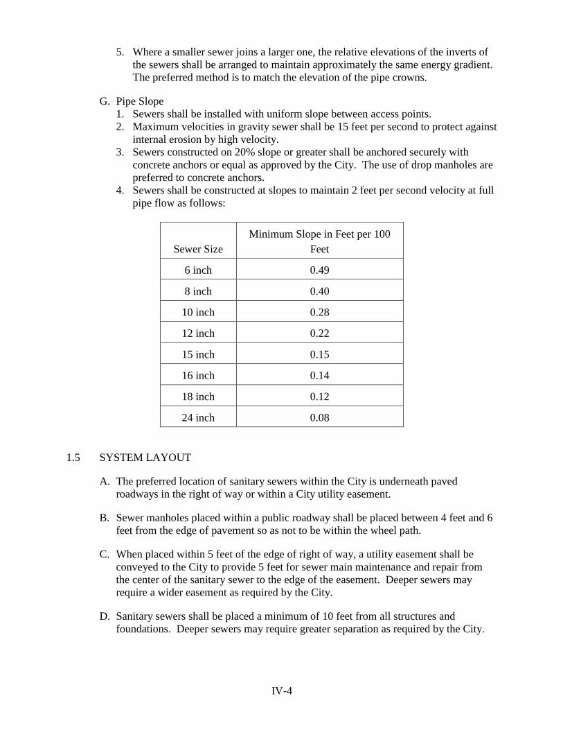
IV-4
5. Where a smaller sewer joins a larger one, the relative elevations of the inverts of
the sewers shall be arranged to maintain approximately the same energy gradient.
The preferred method is to match the elevation of the pipe crowns.
G. Pipe Slope
1. Sewers shall be installed with uniform slope between access points.
2. Maximum velocities in gravity sewer shall be 15 feet per second to protect against
internal erosion by high velocity.
3. Sewers constructed on 20% slope or greater shall be anchored securely with
concrete anchors or equal as approved by the City. The use of drop manholes are
preferred to concrete anchors.
4. Sewers shall be constructed at slopes to maintain 2 feet per second velocity at full
pipe flow as follows:
Sewer Size
Minimum Slope in Feet per 100
Feet
6 inch 0.49
8 inch 0.40
10 inch 0.28
12 inch 0.22
15 inch 0.15
16 inch 0.14
18 inch 0.12
24 inch 0.08
1.5 SYSTEM LAYOUT
A. The preferred location of sanitary sewers within the City is underneath paved
roadways in the right of way or within a City utility easement.
B. Sewer manholes placed within a public roadway shall be placed between 4 feet and 6
feet from the edge of pavement so as not to be within the wheel path.
C. When placed within 5 feet of the edge of right of way, a utility easement shall be
conveyed to the City to provide 5 feet for sewer main maintenance and repair from
the center of the sanitary sewer to the edge of the easement. Deeper sewers may
require a wider easement as required by the City.
D. Sanitary sewers shall be placed a minimum of 10 feet from all structures and
foundations. Deeper sewers may require greater separation as required by the City.

IV-5
E. Provisions shall be made for logical sewer system extensions that will occur within a
reasonable time frame, as determined by the City. Gravity sewer extensions shall be
provided at manholes with 24-inch long stub pipes that are capped watertight.
F. Air Release Valves shall be provided at high points of force mains. Where practical,
high points shall be eliminated by slight adjustments to the pipeline profile.
1.6 COVER, DEPTH, AND SEPARATION
A. Minimum Cover
1. The minimum depth of cover for sanitary sewer pipe shall be 36 inches, measured
from the top of the pipe to the established finished grade, unless otherwise
approved by the City.
2. Where approved to be less than 36 inches of cover, sewers shall be ductile iron
pipe.
3. Sewers shall be installed at a sufficient depth or with adequate velocity to prevent
ice formation due to cooling of the wastewater flows, resulting in blockage of the
flow channel.
B. Maximum depth of gravity sewers shall be 25 feet from ground level to invert.
C. Sewer pipes over 12 feet depth shall be ductile iron pipe.
D. Sanitary sewers and manholes shall normally be separated from water mains by at
least 10 feet horizontally measured edge to edge for parallel installations. When
unusual conditions warrant, the water mains may be laid closer to the sanitary sewer
or manhole provided that:
1. The bottom of the water main shall be at least 18 inches above the top of the
sanitary sewer;
2. Where the vertical separation cannot be maintained, the sewer shall be
constructed of AWWA approved water pipe and pressure tested to 50 PSI in place
without leakage prior to backfilling; and
3. The sewer manhole shall be of watertight construction and tested in place.
E. Sanitary sewers crossing water mains shall normally be separated by having the
bottom of the water main at least 18 inches above the top of the sanitary sewer main.
When unusual conditions warrant, water main crossings may be laid closer to the
sanitary sewer provided that:
1. Sewers passing over or under water mains shall be constructed of AWWA
approved water pipe and hydrostatically pressure tested to 50 PSI in place without
leakage prior to backfilling.
2. Where water mains pass beneath sanitary sewers, additional protection shall occur
by providing:
a. At least 18 inches of separation between the top of the water main and the
bottom of the sanitary sewer;
b. Adequate structural support for the sanitary sewer to prevent undue deflection
and stress on the water main; and
c. The length of the water main pipe be placed as the midpoint of the sewer pipe
such that the joints are equidistant and as far from the sewer as possible.
F. No water mains shall come into contact with any sanitary manhole.

IV-6
G. Private utilities (gas, electric, telecommunications, etc.) shall be a minimum of 24
inches horizontal separation and a minimum vertical clearance of 6 inches from all
sanitary sewer system components, unless otherwise approved by the City.
1.7 MANHOLES
A. Unless otherwise approved by the City, manholes conforming to HRPDC RCS details
SS_01 to SS_03 shall be installed:
1. At the end of each gravity sewer of 8-inch diameter or greater;
2. At all changes in grade, size, or alignment;
3. At all sewer intersections; and
4. At distances not greater than 400 feet.
B. Terminal cleanouts conforming to HRPDC RCS detail SS_13 may be acceptable in
place of manholes, on lines 8-inches in diameter or less, on a case-by-case basis.
C. Manholes connecting pipes less than 24-inches shall be minimum 48-inches diameter.
D. Manholes connecting pipes 24-inches or greater shall be minimum 60-inches
diameter.
E. Manholes shall have benches (invert shaping) installed per HRPDC RCS detail
SS_07.
F. Minimum elevation difference across manhole from inlet to outlet shall be 0.1 feet.
G. A drop pipe should be provided for an upstream sewer entering a manhole at an
elevation of 2.0 feet or more above the manhole invert unless sewer pipe crowns
match elevations, or as may otherwise be required to conform to the use of standard
fittings in the drop pipe construction.
H. Manholes with interior drop connections conforming to HRPDC RCS detail SS_04
shall be 60-inches diameter minimum, unless otherwise approved by the City on a
case-by-case basis.
I. Inlet and outlet pipes shall be joined to the manhole with a gasketed flexible
watertight connection or any watertight connection arrangement that allows
differential settlement of the pipe and manhole wall to take place without destroying
the watertight integrity of the line connections.
J. Sanitary Sewer laterals shall not connect to the main within 5-feet of a manhole.
Laterals upstream and within 5-feet of the manhole shall connect directly into the
manhole where necessary.
K. Manholes receiving discharge from, and within 1,000 feet downstream of, a force
main outlet shall be epoxy coated per HRPDC RCS with a Type B coating to a
minimum dry film thickness of 80 mils.
L. Watertight manhole covers or watertight manhole inserts shall be used when the
manhole top is below the elevation of the 100-year flood/wave action. Ventilation of

IV-7
gravity sewer systems shall be provided where continuous watertight sections greater
than 1,000 feet in length are incurred.
1.8 SURFACE WATER AND AERIAL CROSSINGS
A. Surface water and aerial crossings (sewer bridges) shall only be permitted by the City
on a case-by-case basis.
B. Surface water crossings shall comply with 9VAC25-790-360.
C. Aerial sanitary sewer crossings shall be adequately supported, protected from damage
due to freezing, accessible for repair or replacement, protected from scour, and
located a minimum of 2 feet above the 100 year flood level.
D. Aerial crossings shall be constructed of mechanical joint Class 52 ductile iron pipe
and supported at a minimum of one support per pipe length and within 3 feet of each
joint. Manholes shall be placed at terminal ends of the aerial crossing in natural soils.
E. The design professional shall provide details on the Contract Documents for review
and approval by the City for all aerial and surface water crossings.
1.9 SERVICE CONNECTIONS
A. Service connections to the public sanitary sewer system shall have a cleanout
conforming to HRPDC RCS detail SS_11 or SS_12 located at the right of way line or
edge of the sanitary sewer easement. Services 8-inch or greater may use a manhole
instead of a cleanout upon approval by the City.
B. Each parcel shall have an individual service lateral and property line cleanout.
C. Minimum service lateral size shall be 4-inch for single residential units.
D. Minimum service lateral size shall be 6-inch for non-residential properties and for
laterals serving more than one residential unit.
E. Minimum slope, unless otherwise approved by the City:
1. 1/4-inch per foot (2.08%) for 4-inch laterals
2. 1/8-inch per foot (1.04%) for 6-inch laterals
3. 8-inch and larger laterals shall conform to the minimum slopes for sewer mains.
F. Pipes, fittings, and appurtenances on the customer side of the property line cleanout
are private and shall be governed by the Uniform Statewide Building Code as adopted
by the locality having jurisdiction.
1.10 TAPS AND MAIN CONNECTIONS TO EXISTING MAINS
A. Connections shall be made to sewers by replacing a length of pipe with branch
fittings, or a clean opening cut with tapping equipment and a wye type of connection
completed and sealed. In some instances a tee-saddle or tee-insert may be attached to
the sewer sub-main to provide a connection.

IV-8
B. All connections to sewers and manholes shall be made so as to prevent structural
damage and infiltration. To meet future needs, stubs, wyes, and tees may be installed
if plugged tightly.
C. Taps on the City of Williamsburg force main system shall only be accomplished by
approved contractors. Coupons shall be retrieved and provided to the City inspector.
1.11 THRUST RESTRAINT
A. Restraint of force mains shall comply with the requirements for restraint of pipelines
in the City’s water distribution system.
B. Aerial sewer crossings and sewers installed in earthen fills shall be fully restrained
which shall extend a minimum of 25 feet into adjacent fills.
PART 2 MATERIALS & EXECUTION
2.1 HRPDC REGIONAL CONSTRUCTION STANDARDS
A. Sanitary sewers to be conveyed to the City of Williamsburg shall be in accordance
with the materials and construction specifications contained in the HRPDC Regional
Construction Standards (6th Edition) as amended and the Special Provisions
contained herein.
2.2 PROFESSIONAL CERTIFICATION
A. As discussed in 9 VAC 25-740-240.C., the referenced design documents for all
components of a project not funded through the Water Quality Improvement Fund
shall be certified by the design professional to be in substantial compliance with Part
III – Manual of Practice, of the Sewage Collection and Treatment Regulations (9
VAC 25-790-310 et seq.).
B. Certification shall be noted on the plans, preferably on the cover sheet.
2.3 SPECIAL PROVISIONS
A. Section 200 – Products and Materials
1. Replace paragraph V.5.3.B.2 (page 200-9) with:
“2. Casing Spacers: Provide one of the following type to center the carrier pipe
within the steel encasement pipe:
a. UHMW polymer runners and stainless steel shell.
1) Two piece shell of T-304 stainless steel (minimum 14 gauge thickness)
with four runners of T304 stainless steel (minimum 10 gauge
thickness) welded to the shell; a minimum of 3 T304 stainless steel
fasteners on each side, a non-metallic shell liner and four 8-inch wide
runners (centered configuration) of ultra-high molecular weight
(UHMW) polymer with abrasion resistance and low coefficient of
friction.

IV-9
2) Cascade Waterworks Manufacturing CCS Spacers or approved equal.
3) Provide 2 spacers per length of water main pipe.
b. RACI Spacers
1) Non-metallic, preformed, multi-segment ring with a minimum number
of high density polyethylene (HDPE) projections equal to the nominal
diameter (in inches) of the carrier pipe.
2) RACI Spacers North America or approved equal
3) Provide minimum 3 spacers for each length of carrier pipe with two
spacers at each end of the casing.”
2. Replace the first paragraph of V.5.10.A.11.b (page 200-14) with:
“b. Where corrosion resistant linings are identified in the Contract Documents
for ductile iron pipe and fittings, linings shall be ceramic epoxy coating.”
3. Replace paragraph V.5.10.G.5 (page 200-22) with:
“5. Concrete reaction blocking shall not be used except where permitted by the
City. Where permitted, tapping sleeve, tees, retainer glands, and hardware
shall be wrapped with 6 mil polyethylene prior to placing the concrete.”
4. Replace paragraph V.5.19 (pages 200-37 to 200-48) with:
“5.19 WATER DISTRIBUTION SYSTEMS
A. Comply with City of Williamsburg Standard Specifications for Water
Distribution Systems.”
B. Section 530 – Abandonment of Existing Pipelines and Structures
1. Replace the title of paragraph II.2.1.A (page 530-2) with:
“A. Existing Pipelines (Larger than 4-inch Diameter)”
2. Replace paragraph II.2.1.B (page 530-2) with:
“B. Existing Pipelines (4-inch Diameter and Smaller)
Unless specifically called for in the Contract Documents, pipelines 4-inch
diameter and smaller shall be removed or abandoned in place without filling
with flowable fill. A minimum of 12-inches of pipe shall be removed from
ends to prevent electrical continuity and false tracing signals. Ends of pipes
to be abandoned in place shall be crimped or plugged at terminal ends or as
directed by the City.”
3. Replace paragraph II.2.1.D.2 (page 530-3) with:
“2. If water meters are to be removed and salvaged, Contractor shall contact the
Department of Public Utilities at (757) 220-6140, who will set a work order

IV-10
to remove the meter. Contractor shall not tamper with nor close valves on
the public water distribution system, without direct supervision by the City.”
4. Replace paragraph II.2.1.E.3 (page 530-3) with:
“3. Laterals to be abandoned on a main line to remain active shall be plugged or
capped watertight within 12-inches of the main connection. A minimum of
12-inches of the lateral shall be removed to fully disconnect the abandoned
section from the main prior to plugging. Alternatives to open-cut
abandonment at the main will be considered by the City on a case-by-case
basis.”
C. Delete Section 801 – Water Distribution Systems (pages 801-1 to 801-25) as it is
superseded by the City of Williamsburg Standard Specifications for Water
Distribution Systems.
D. Section 802 – Sanitary Gravity Sewer Systems
1. Delete paragraph II.2.4.B.1.b (page 802-9) as the City does not require deflection
testing unless warranted by visual inspection or internal television inspection.
2. Append the following to paragraph II.2.4.B.1.c.(1)(a) (page 802-10) with:
“Laterals that connect directly into a manhole do not require air testing.”
3. Delete paragraph II.2.4.B.1.c.(2) (pages 802-11 to 802-12) as the City does not
require infiltration testing.
E. Section 803 – Sanitary Force Main Systems
1. Replace paragraph II.2.5.B (page 803-7) with:
“B. Concrete reaction blocking shall not be used except where permitted by the
City. Where permitted, tapping sleeve, tees, retainer glands, and hardware
shall be wrapped with 6 mil polyethylene prior to placing the concrete.
Blocking shall be placed between undisturbed earth and the fitting to be
restrained.”
2. Replace paragraph II.2.6.A (page 803-7) with:
“A. For pipe diameters larger than 16-inches, connections shall be made as
detailed in the Contract Documents.”
F. Section 810 – Sewer Line Cleaning
1. Replace the first sentence of paragraph II.2.2.A.4 (page 810-4) with:
“Existing flows shall not be interrupted for periods longer than necessary, but in
no case shall back-ups into homes or sewer overflows be permitted.”

IV-11
G. Standard Details, EW_01 – Pipe Bedding Details
1. Append the notes on Sheet No. 2 of 2 with:
“10. All PVC pipe shall use Type IV bedding; all DI pipe shall use Type III
bedding.”
H. Standard Details, SS_05 – Sanitary Sewer Exterior Drop Manhole
1. Append the notes on Sheet No. 1 of 1 with:
“3. Exterior Drop Manholes shall only be used with prior approval of the City
after review on a case-by-case basis.”
I. Standard Details, SS_14 – Sanitary Sewer Service Connection
1. Change the label on Sheet No. 1 of 1 from:
“PVC or Cast Iron Cap (with Rigid Coupling)”
to
“PVC or Cast Iron Threaded Cap/Plug with 2-Inch Square Nut”
J. Standard Details, SS_20 – Sanitary Sewer Service Connection - Alternate
1. Delete Sheet Nos. 1 of 2 & 2 of 2 as the detail is not used in the City.
K. Standard Details, SS_21 – House Lateral Cleanout Alternate
1. Delete Sheet No. 1 of 1 as the detail is not used in the City.
L. Standard Details, WS_03 – Manual Air Vent Assembly
1. Replace Note 2 on Sheet No. 2 of 2 with:
“2. Omit saddle unless otherwise directed by the City. Direct tap only.”
2. Append the notes Sheet No. 2 of 2 with:
“9. Omit check valve on Sanitary Force Main installations.”
M. Standard Details, WS_04 – Steel Casing Detail
1. Delete Notes 3 and 4 on Sheet No. 2 of 2.
2. Append the notes on Sheet No. 2 of 2 with:
“3. Option 1 (flush air vent) for casing leak detection shall be used unless
otherwise approved by the City. No check valve shall be installed. Cover
casting shall be stamped ‘S’ for sewer.”

V-1
APPENDIX A – WATER SYSTEM DATA SHEET
DATE: Plan #:
PROJECT NAME:
PROJECT LOCATION (Lat-Long):
PLANS PREPARED BY:
======================================================================
PROJECT SERVICE AREA DESIGN CONDITIONS:
Connection
Type
Number of
Connections
Average Day Maximum Day
GPD/Connection GPD GPD/Connection GPD
Residential
Commercial
Industrial
Other
(identify)
TOTAL
Pipe Size Pipe Length Pipe Material
HYDRAULIC EVALUATION OF THIS PROJECT:
Flows Minimum Pressure
Peak Hour Demand
Maximum Day Demand
Design Fire Flow
Maximum Day + Fire Flow
No. of Fire Hydrants

VI-1
APPENDIX B – SANITARY SEWER SYSTEM DATA SHEET
DATE: Plan #:
PROJECT NAME:
PROJECT LOCATION (Lat-Long):
PLANS PREPARED BY:
======================================================================
PROJECT SERVICE AREA DESIGN CONDITIONS:
Connection
Type
Number of
Connections
Average Flow Peak Flow
GPD/Connection GPD GPD/Connection GPD
Residential
Commercial
Industrial
Other
(identify)
TOTAL
(gravity sewer or force mains only – do not include service laterals)
Pipe Size (in) Pipe Length (LF) Pipe Material
Manhole Size Number Average Depth (ft)
Standard (48” diameter)
60” diameter
Cleanouts
RECEIVING PUMP STATION:

VII-1
APPENDIX C – WATER SYSTEM STANDARD DETAIL DRAWINGS
The following list of drawings are based on the January 1996 edition of the City Water
Distribution System Construction Standards and Specifications details. Substituted Drawings
denoted below are from the Sixth Edition of the Hampton Roads Planning District Commission
Regional Construction Standards (HRPDC RCS) as herein amended. Drawings without a
notation are included in this appendix. Some former drawing numbers (i.e. W15.0 Automatic
Air Release Valve) have been replaced and descriptions changed.
No. Description HRPDC RCS Substitute Drawing
W1.0 Pipe Trench Detail EW_01, EW_02, & EW_03
W2.0 Typical Highway Crossing WS_04
W3.0 Railroad Crossing WS_04
W4.0 Concrete Cradle and Encasement WS_09
W5.0 Concrete Thrust Blocks for Tees
W6.0 Buttresses for Horizontal Bends Deleted
W7.0 Buttresses for Vertical Bends Deleted
W8.0 Anchorages for Vertical Bends Deleted
W9.0 Curvature of Ductile Iron Pipeline
W10.0 Typical Valve and Valve Box WS_01 & WS_02
W11.0 Typical Meter Setting 5/8”x3/4” & 1
W12.0 Typical Meter Setting 1 ½” & 2”
W13.0 Meter Vault Detector Check w/ Domestic Deleted
W13.1 3” & 4” Domestic Water Meter Vault
W14.0 Typical Fire Hydrant Setting
W15.0 Typical Single Detector Check Valve for Fire
Suppression Systems
W16.0 Manual Air Release Valve WS_03
W17.0 Dead End Blow-off WD_05
W18.0 Standard Paving Restoration Details RC_01
W19.0 Typical Connection to 2” SCH 80 PVC Pipe

CONCRETE THRUST BLOCK DIMENSIONS FOR TEES
CITY OF WILLIAMSBURG
DEPT. OF PUBLIC WORKS & UTILITIESENGINEERING DIVISION
401 LAFAYETTE STREET, WILLIAMSBURG, VA 23185(757) 220-6140
CONCRETE THRUST BLOCKS FOR TEES
WATER DISTRIBUTION SYSTEM STANDARDS & SPECIFICATIONS
By:
File:
Scale:
Date:
Dwg Number
5.0
A.SMALL
W-5-0
N.T.S.
03/05/20

PUSH-ON JOINTS
MECHANICAL JOINTS
CITY OF WILLIAMSBURG
DEPT. OF PUBLIC WORKS & UTILITIESENGINEERING DIVISION
401 LAFAYETTE STREET, WILLIAMSBURG, VA 23185(757) 220-6140
CURVATURE OF DUCTILE IRON PIPELINE
WATER DISTRIBUTION SYSTEM STANDARDS & SPECIFICATIONS
By:
File:
Scale:
Date:
Dwg Number
9.0
A.SMALL
W-9-0
N.T.S.
03/05/20
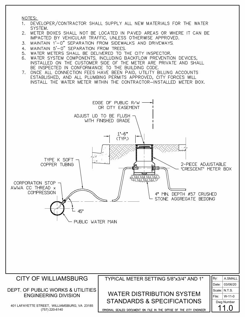
CITY OF WILLIAMSBURG
DEPT. OF PUBLIC WORKS & UTILITIESENGINEERING DIVISION
401 LAFAYETTE STREET, WILLIAMSBURG, VA 23185(757) 220-6140
TYPICAL METER SETTING 5/8"x3/4" AND 1"
WATER DISTRIBUTION SYSTEM STANDARDS & SPECIFICATIONS
By:
File:
Scale:
Date:
Dwg Number
11.0
A.SMALL
W-11-0
N.T.S.
03/06/20

CITY OF WILLIAMSBURG
DEPT. OF PUBLIC WORKS & UTILITIESENGINEERING DIVISION
401 LAFAYETTE STREET, WILLIAMSBURG, VA 23185(757) 220-6140
TYPICAL METER SETTING 1 1/2" AND 2"SINGLE METER
WATER DISTRIBUTION SYSTEM STANDARDS & SPECIFICATIONS
By:
File:
Scale:
Date:
Dwg Number
12.0
A.SMALL
W-12-0
N.T.S.
03/06/20
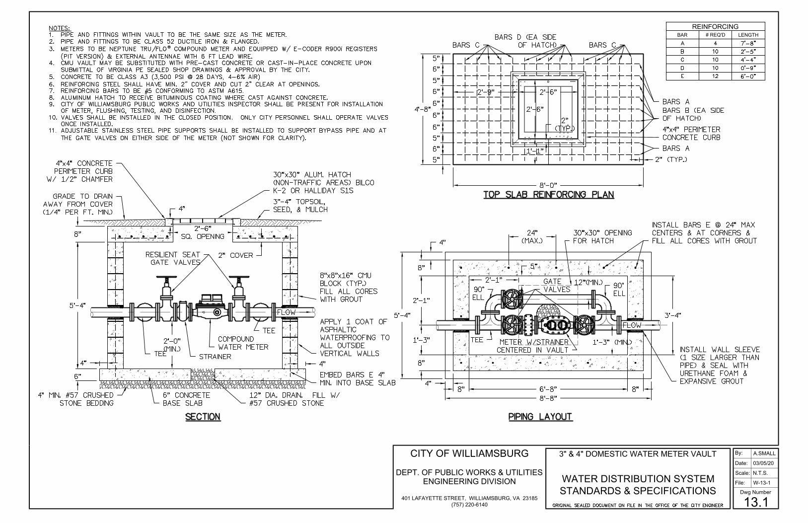
®
REINFORCINGBAR # REQ'D LENGTH
3" & 4" DOMESTIC WATER METER VAULT
WATER DISTRIBUTION SYSTEM STANDARDS & SPECIFICATIONS
By:
File:
Scale:
Date:
Dwg Number
13.1
A.SMALL
W-13-1
N.T.S.
03/05/20CITY OF WILLIAMSBURG
DEPT. OF PUBLIC WORKS & UTILITIESENGINEERING DIVISION
401 LAFAYETTE STREET, WILLIAMSBURG, VA 23185(757) 220-6140

··
CITY OF WILLIAMSBURG
DEPT. OF PUBLIC WORKS & UTILITIESENGINEERING DIVISION
401 LAFAYETTE STREET, WILLIAMSBURG, VA 23185(757) 220-6140
TYPICAL FIRE HYDRANT SETTING
WATER DISTRIBUTION SYSTEM STANDARDS & SPECIFICATIONS
By:
File:
Scale:
Date:
Dwg Number
14.0
A.SMALL
W-14-0
N.T.S.
03/06/20
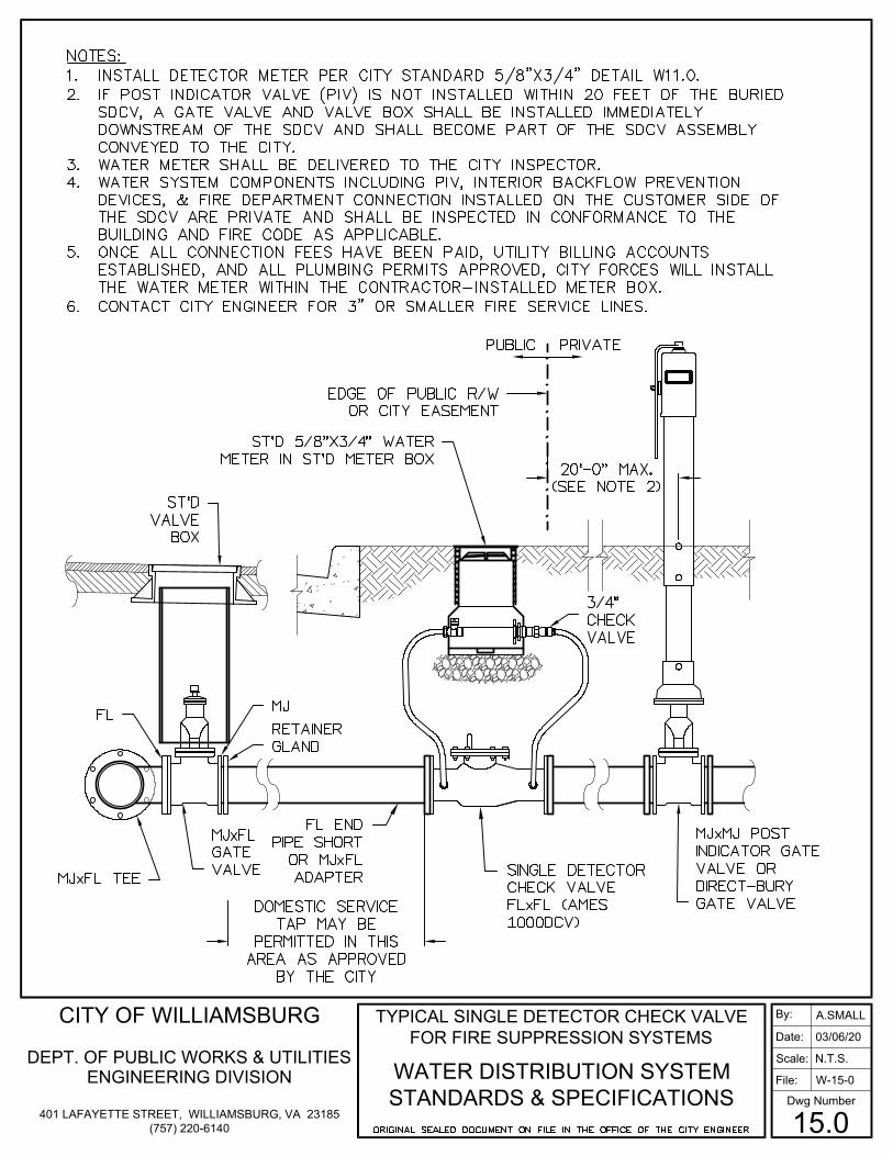
CITY OF WILLIAMSBURG
DEPT. OF PUBLIC WORKS & UTILITIESENGINEERING DIVISION
401 LAFAYETTE STREET, WILLIAMSBURG, VA 23185(757) 220-6140
TYPICAL SINGLE DETECTOR CHECK VALVE FOR FIRE SUPPRESSION SYSTEMS
WATER DISTRIBUTION SYSTEM STANDARDS & SPECIFICATIONS
By:
File:
Scale:
Date:
Dwg Number
15.0
A.SMALL
W-15-0
N.T.S.
03/06/20
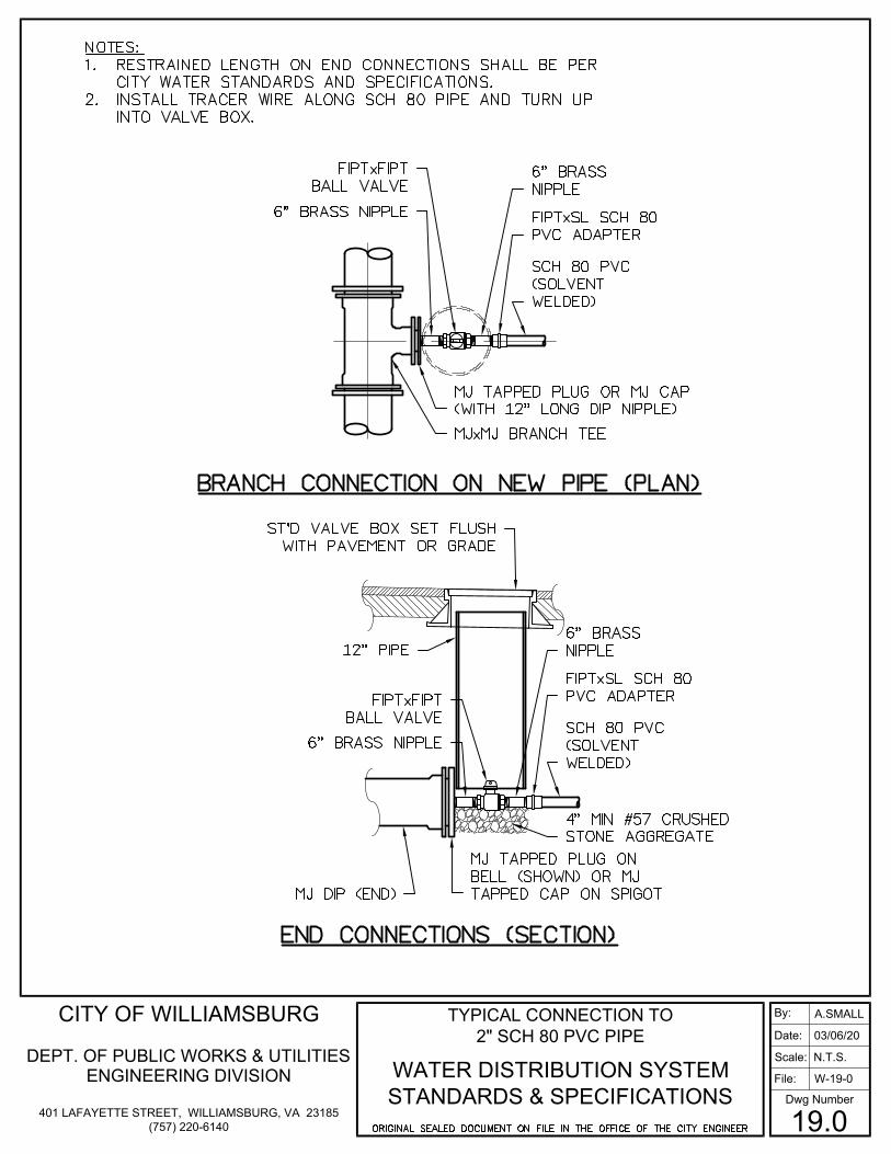
CITY OF WILLIAMSBURG
DEPT. OF PUBLIC WORKS & UTILITIESENGINEERING DIVISION
401 LAFAYETTE STREET, WILLIAMSBURG, VA 23185(757) 220-6140
TYPICAL CONNECTION TO 2" SCH 80 PVC PIPE
WATER DISTRIBUTION SYSTEM STANDARDS & SPECIFICATIONS
By:
File:
Scale:
Date:
Dwg Number
19.0
A.SMALL
W-19-0
N.T.S.
03/06/20