water gas shift membrane reactor model in aspen plus€¦ · simulation package aspen plus. the...
TRANSCRIPT

November 2002 ECN-CX--02-105CONFIDENTIAL
WATER GAS SHIFT MEMBRANE REACTOR MODELIN ASPEN PLUS
Installation and Operation Manual Version 2
J.W. DijkstraG.P. Leendertse
F.W.A. TillemansY.C. van Delft
RevisionsA 28 August 2002; First versionB 8 November 2002; Final versionMade by:
J.W. Dijkstra
Approved by:
Y.C. van DelftChecked by:
G.P. Leendertse
Issued by:
P.T. Alderliesten
ECN Energy Efficiencyin Industry
Separation Technology

2 ECN-CX--02-105
PrefaceThis document describes the installation and operation of the second version of the water gasshift membrane reactor model in Aspen Plus. The model described in this report is developed bythe Energy research Centre of the Netherlands (ECN) in the project “Membrane water gas shiftreactor- CO2 Capture project” (ECN project nr. 7.6457). The work is funded by the USDepartment of Energy and the CO2 Capture project.
AbstractThe CO2 Capture Project (CCP) is an initiative of ten major energy companies to develop costeffective technologies for the Capture and Geologic Storage of carbon dioxide. One of thetechnologies to be developed is the production of hydrogen rich fuel gas to be used as a carbon-free fuel in refinery heaters, gas turbines and for power generation from fossil fuel feedstock bymeans of a water gas shift membrane reactor system. The aim of this project is to develop thewater gas shift membrane reactor technology to proof of concept.
Within the project a water gas shift membrane reactor model has been made for the processsimulation package Aspen Plus. The membrane reactor model is implemented as an Aspen PlusUser Model (Aspen Plus, version 11.1) written in Fortran.
The installation and operation of the first version of the water gas shift membrane reactor modelis described in this report. The model simulates a countercurrent water gas shift membranereactor with microporous and dense membranes and copes with the isothermal and non-isothermal operation of the membrane reactor.

ECN-CX--02-105 3
CONTENTS
LIST OF TABLES 4
LIST OF FIGURES 4
SUMMARY 5
1. INTRODUCTION 7
2. WATER GAS SHIFT MEMBRANE REACTOR MODEL 92.1 The WGSMR model 92.2 The model implementation structure 9
3. INSTALLING AND USING THE USRWGS-SOFTWARE WITH THE WGSMR-MODEL 113.1 What the installation intends to do 113.2 System requirements 113.3 Installation procedure 113.4 Verification procedure 12
4. GETTING STARTED 13
5. SPECIFYING A PROBLEM 175.1 Introduction 175.2 Which parameters to specify 175.3 Guidelines for the values of input data from Aspen Plus 185.4 Guidelines for the values in the Configuration (cfg-) file 19
6. NOTES FOR OPERATING THE MODEL 25
7. READING OUTPUT 27
REFERENCES 29
APPENDIX A THE CONTENTS OF THE CFG-FILE 31
APPENDIX B THE CONTENTS OF THE NMC-FILE 33

4 ECN-CX--02-105
LIST OF TABLES
Table 5.1 Guidelines for values of input data from Aspen Plus .................................................18Table 5.2 Guidelines for values of user definable input parameters in the cfg-file....................20Table 5.3 Fixed input parameters in the cfg-file ........................................................................22Table 7.1 Overview of model output written to the history file ..................................................27
LIST OF FIGURES
Figure 2.1 Schematic representation of the water gas shift membrane reactor ...........................9Figure 4.1 Drag the USER icon in the flowsheet ........................................................................13Figure 4.2 Model connectivity ....................................................................................................14Figure 4.3 Specifying the USER block (1): Specifications tab....................................................14Figure 4.4 Specifying the User block (2): Stream Flash tab.......................................................15Figure A.1 The template cgf-file (testwgs.cfg)............................................................................33Figure B.1 The template nmc-file (testwgs.nmc) ........................................................................35
ECN-CX--02-105 5
SUMMARY
The CO2 Capture Project (CCP) is an initiative of ten major energy companies to develop costeffective technologies for the Capture and Geologic Storage of carbon dioxide. One of thetechnologies to be developed is the production of hydrogen rich fuel gas to be used as a carbon-free fuel in refinery heaters, gas turbines and for power generation from fossil fuel feedstock bymeans of a water gas shift membrane reactor system. The aim of this project is to develop thewater gas shift membrane reactor technology to proof of concept.
One of the activities of ECN in the project is the development of a mathematical model of themembrane reactor, to be integrated into the process simulation package Aspen Plus, with thecapability to reflect four membrane types (silica, zeolite, palladium alloy and proton conductiveperovskite membranes). The first version of the membrane reactor model including only themicroporous transport model, has been made for the process simulation package Aspen Plus.The membrane reactor model is implemented as an Aspen Plus User Model (Aspen Plus,version 11.1) and is written in Fortran. The installation and operation of the second version ofthe water gas shift membrane reactor model is described in this report.
The model simulates a countercurrent water gas shift membrane reactor with microporousmembranes (silica and zeolite) and dense (palladium and proton conducting) membranes andcopes with the isothermal and non-isothermal operation of the membrane reactor. Themembrane reactor model is capable of handling all types of gaseous components, but isrestricted to deal with only the relevant components (H2, CO, CO2, H2O, N2 and CH4) in reactionand permeation.

6 ECN-CX--02-105

ECN-CX--02-105 7
1. INTRODUCTION
The CO2 Capture Project (CCP) is an initiative of ten major energy companies to develop costeffective technologies for the Capture and Geologic Storage of carbon dioxide. This is toprovide control options for CO2 from the combustion processes operated by these companiesand others. One of the technologies to be developed is the production of hydrogen rich fuel gasto be used as a carbon-free fuel in refinery heaters, gas turbines and for power generation fromfossil fuel feedstock by means of a water gas shift membrane reactor system. The envisionedapplication of a water gas shift membrane reactor is to convert the CO in the syngas from agasifier to produce a hydrogen rich fuel gas stream and a CO2 rich stream which can becompressed for geological sequestration with minimum further treatment. The aim within theCCP project is to develop the water gas shift membrane reactor technology to proof of concept.The system is to be designed for operation with sulphur containing feeds from a refinery, suchas residual oil, fed to the gasifier.
One of the activities of ECN in the project is the development of a mathematical model of themembrane reactor, to be integrated into the process simulation package Aspen Plus, with thecapability to reflect four membrane types (silica, zeolite, palladium alloy and proton conductingperovskite membranes). The second version of the membrane reactor model includes themicroporous transport model for silica and zeolite membranes, as well as a model for densemembranes (palladium and proton conducting membranes operating below 500°C). The watergas shift membrane reactor model is only to be used by Fluor Daniel within and during theproject DOE/WGS5: Membrane Water Gas Shift Reactor Development Study. The installationand operation of the second version of the model is described in this report. Chapter 2 gives abrief outline of the model. The installation and use of this so-called WGSMR model is describedin Chapter 3. In Chapter 4 and 5 setting up and specifying a problem are described. Finally,notes for operating the model and a description of the model output are given in Chapter 6 and7.

8 ECN-CX--02-105

ECN-CX--02-105 9
2. WATER GAS SHIFT MEMBRANE REACTOR MODEL
The working principle of the water gas shift membrane reactor (WGSMR) is presented in Figure2.1. The feed consists of syngas. At the feed side of the membrane reactor the (exothermic)water gas shift reaction takes place:
CO+H2O ! CO2+H2
Parallel to this gas-phase equilibrium reaction permeation of hydrogen through the membranetakes place. The removal of hydrogen shifts the equilibrium of the reaction to the right-handside. A sweep gas is introduced to the permeate side to increase the hydrogen permeation rate.
MEMBRANE
Feed
Sweep
Retentate
Permeate
WGSMR
SHIFT REACTION
H2
Figure 2.1 Schematic representation of the water gas shift membrane reactor
2.1 The WGSMR modelThe water gas shift membrane reactor model consists of mass and energy balances for eachcomponent on both sides of the membrane combined with equations for reaction andpermeation. More information on the used reaction and permeation equations can be found inthe functional specifications (Delft, 2002).
The membrane reactor model is implemented as an Aspen Plus User Model and is written inFortran. The model takes its input directly from Aspen Plus, and returns output directly toAspen Plus. The unit operation performed by the model is to compute the composition ofspecies in an incoming feed gas and sweep gas, as a consequence of the WGS-reaction takingplace in the feed gas and the selective permeation of species in the feed gas through amicroporous membrane.
Membrane and reaction specific input data has to be supplied in a separate data file. Themembrane surface area and the ratios of reaction volume to membrane surface area on the feedand permeate side are specified in Aspen Plus and are accessible for Fortran, SPEC andSENSITIVITY blocks in Aspen Plus. The model output data returned to Aspen are outlet streamproperties (retentate respectively permeate flow). The model output with membrane specificdata is added to the Aspen Plus history file. The model is capable of handling all types ofgaseous components, but is restricted to deal with only the relevant components (H2, CO, CO2,H2O, N2 and CH4) in reaction and permeation. The feed gas and sweep gas flow in acountercurrent fashion on both sides along the membrane.
2.2 The model implementation structureThe WGSMR-model is a user model, written in Fortran. Added to the Aspen Plus (Aspen Plus,version 11.1) software (using a special installation script) it can be applied as a unit operationblock in user-definable flowsheets.

10 ECN-CX--02-105
The name of the Fortran subroutine that forms the interface with the Aspen Plus system isusrwgs (the first 3 characters of the name are prescribed in Aspen Plus). For this reason the dllwhich contains the binary version of the model is also called: usrwgs.dll.
For the model to be used in a flowsheet the user must introduce a block User ('Unit operationdefined by user-supplied Fortran subroutine') with a Subroutine/Modelname usrwgs, but havingan arbitrary blockname. The block must have 2 incoming flows (for the feed and the sweep gas)and likewise two outgoing flows, the retentate and the permeate gas. Within the flowsheet thetemperature and the pressure of the incoming flows must be specified. For the permeation 3membrane-specific parameters (Area, Volume-Area ratios) are required: their values must bedefined using the REAL-parameter option of the User block.
The complete problem definition for the WGSMR-model contains, in addition to the flowsheet,two special textfiles with numerical parameters for the model computations are needed. In viewof their file-extensions these textfiles are referred to as a cfg- and a nmc-file. For a specificproblem the 'sample' cfg-file (occurring on the installation disk) only needs minimalmodifications. The nmc-file doesn't require any modifications. What does have to be changed,however, is the name of the files: these must be in agreement with the (membrane) blocknamein the flowsheet. A block 'case', for instance, requires the actual files case.cfg and case.nmc.One last file, also to be placed in the same subdirectory where the bkp-file (or apw-file), the cfgand nmc-file occur, is usrwgs.opt. This file, which has to be copied from the installation disk tothe working directory, is needed by the Aspen Plus system to trace usrwgs.dll.

ECN-CX--02-105 11
3. INSTALLING AND USING THE USRWGS-SOFTWARE WITHTHE WGSMR-MODEL
3.1 What the installation intends to doThe model is shipped as a so-called dynamically linked library named usrwgs.dll. In order tomake it accessible from Aspen Plus flowsheets that are defined (through bkp- or apw-files) indifferent working directories, usrwgs.dll has to be copied to a specific system subdirectory ofAspen Plus. This task is performed by the simple script in the file instwgs.bat, which is shippedalong with the model. The instwgs.bat-file can be edited and indeed needs modifications if theAspen Plus-software has not been installed in the default locations chosen by the Aspen Plusinstallation software. Specifically, the default location, for version 11.1 of Aspen Plus, is:
C:\Program Files\AspenTech\APRSYSTEM 11.1\Engine\xeq
Files pertaining to the sample problem described in the documentation have been included in theinstallation directory. The sample problem is defined by an Aspen Plus bkp-file (with theflowsheet definition), a cfg-file and nmc-file (both with constants for the model computations)and the file usrwgs.opt. To verify the results of the simulations the history file generated byAspen Plus (when running the problems at ECN) has also been included.
3.2 System requirementsAspen Plus version : 11.1Platform simulation engine : PCHardware requirements : Same as requirements for Aspen Plus 11.1Operating system : Windows 2000 or Window NTFortran compiler : not required
3.3 Installation procedureTo actually install the WGSMR-model, perform the following steps:1. Copy the contents of the installation directory (plus the subdirectory ‘dll’ with contents)
from the CD-ROM to a suitable working directory on the hard disk. This working directory(say, MyWorkFolder) is the (newly created or existing) location where the first Aspen Plustest run - using the shipped sample problem - is to be performed. The copy can of course becarried out in the Explorer or a similar environment. If the copy was successful,MyWorkFolder contains 6 files:• testwgs.bkp• testwgs.nmc• testwgs.cfg• usrwgs.opt• usrwgsmanual.pdf• readme.htm
and a subdirectory dll containing one file:• usrwgs.dll
2. In the Explorer navigate to the working directory and double-click on the file instwgs.bat.This batch file completes the installation procedure.

12 ECN-CX--02-105
3.4 Verification procedureTo verify that the installation was successful, perform the following steps:1. Double click on the file testwgs.bkp. This will make the Aspen Plus 11 user interface read its
input (the flowsheet) from testwgs.bkp. Alternatively - and necessary if the bkp-files are notassociated with Aspen Plus 11 - start the Aspen Plus 11 user interface explicitly. In theAspen Plus startup menu, specify the bkp-file with the sample problem by double clicking on'More Files'. Browse to MyWorkFolder and select testwgs.bkp.
2. In the next 'Connect to Engine' menu, presented by the Aspen Plus user interface, choose'Local PC' as server type
3. The Aspen Plus user interface now shows the flowsheet: Begin the simulation, e.g. by usingthe Start (>) button.
4. The results show up in the flowsheet. More detailed results can be seen in the History File(Aspen Menu: <View> <History>). Compare these results with those in the file testwgs.hisin MyWorkFolder (which can be viewed in a text editor or printed).

ECN-CX--02-105 13
4. GETTING STARTED
The membrane reactor model is called from a USER unit operation in Aspen Plus. A problemcontaining a water gas shift reactor can be set up by implementing the user model in an existingflowsheet, or to modify the sample problem towards a new problem. For additional informationabout User Models in Aspen Plus, see the Aspen Plus <User Models> manual.
Step 1: Make the appropriate flowsheet
1. Create a new (sub) directory on the hard disk of the PC, this directory will be referred to asthe ‘problem directory’.
2. Create a new flowsheet by either:a) copying the sample flowsheet testwgs.bkp file into the problem directoryb) copying an existing flowsheet bkp-file into the problem directoryc) create a new flowsheet from scratch and save this file as bkp-file in the problem
directory*
*= If a new flowsheet is to be created the recommended order of the components to be enteredin the COMPONENT section of Aspen Plus is CH4, H2O, CO2, H2, N2, CO. Othercomponents can be entered after these components. Doing this will prevent some of the need formodifying the cfg-file later on in step 2.
3. Open the flowsheet bkp-file. If no membrane reactor is present, add a USER unit operationblock by dragging the corresponding icon in the flowsheet. (See Figure 4.1).
Figure 4.1 Drag the USER icon in the flowsheet
4. Specify the blockname of the WGSMR unit operation with <right mouse button><Renameblock> Renaming can be also done by clicking the block and pressing CTRL-M. Forconvenience, we will assume a blockname name1 here.

14 ECN-CX--02-105
5. Connect two inlet streams, the feed and sweep stream (in that order!) and two outlet streams,retentate and permeate stream (in that order!) to the block. (See Figure 4.2).Then specify the inlet streams (unless the streams are output streams from other blocks)
Figure 4.2 Model connectivity
ABC
USRWGS
3
Figure 4.3 Specifying the USER block (1): Specifications tab
6. Double-click the model and fill in the name of the membrane reactor model ‘USRWGS’,without the extension dll (see Figure 4.3).
7. Double-click the USER model and specify the number of REAL parameters to 3. (See Figure4.3).

ECN-CX--02-105 15
8. Fill in the REAL parameters. The REAL parameters correspond from top to bottom withrespectively:First parameter A in Figure 4.3 Membrane surface areaSecond parameter B in Figure 4.3 Feed side (volume/membrane surface area) ratioThird parameter C in Figure 4.3 Permeate (side volume/membrane surface) area ratioNote that the order in which the parameters are specified is fixed. The first is always themembrane surface area etc.Since no reaction is present on the permeate side the third parameter has no relevance andwill not be used in the model.
9. Specify the Stream flash options (see Figure 4.4) click the STREAM FLASH taba) Select the stream =RETENTATE (or the name of the retenate stream) and then selectFlash type = TEMPERATURE & PRESSUREb) Select the stream =RETENTATE (or the name of the retenate stream) and then selectFlash type = TEMPERATURE & PRESSURE
(Aspen Plus, version 11.1)
Temperature& Pressure
For both theretenate and
permeatestream
NAME1
Figure 4.4 Specifying the User block (2): Stream Flash tab
Step 2: Make the appropriate cfg-file
10. Copy the sample testwgs.cfg into the problem directory and rename testwgs to the samename as that of the user block in the flowsheet (in our case name1.cfg).
Open name1.cfg in a text editor like Wordpad, and modify some of the input parameters. Notethat only a small number of the input parameters in the file is to be changed by a user. Moredetails on those parameters can be found in Table 5.2.Make sure that the order of the components (and corresponding coefficients) in the cfg-filethe order in Aspen Plus (See Table 5.2 for the requirements). This holds for• Reacting components• Reaction stoichiometric coefficients• Reaction power law coefficients• Permeating components

16 ECN-CX--02-105
• Permeation Q(o)-values• Permeation activation energies• Permeation power law coefficientsIf the sample problem testwgs.bkp is used as a basis the order should be correct.Also, if a new problem is set up from scratch while using the guideline for the order of thecomponents on page 13, the order should be correct.
Step 3: Make the appropriate nmc-file
11. Copy the sample testwgs.nmc file into the problem directory rename testwgs to the samename as that of the user block in the flowsheet (in our case name1.nmc).The contents of the nmc-file should not be modified by the user.
Note: if multiple membrane reactors are present in the flowsheet then multiple cfg-files andnmc-files are to be specified, each having a different name which corresponds with the name inthe flowsheet. In this way every membrane reactor can have its own specifications.
Step 4: Make the appropriate so-called DLOPT-file for Aspen Plus
12. Copy the file usrwgs.opt to the working directory where the files created in steps 1 – 3 arelocated (in case this working directory is different from the one used in the Verificationstep).
Step 5: In the Aspen Plus user interface specify the name of the DLOPT-file
13. Select the Run-menu, choose Settings, choose the tab Engine Files and in the LinkerOptions field of the Miscellaneous Files section, specify usrwgs.opt

ECN-CX--02-105 17
5. SPECIFYING A PROBLEM
5.1 IntroductionA problem containing a membrane reactor is specified through data in 3 files:1. the Aspen Plus bkp- or apw-file (the flowsheet),2. the cfg-file (constants for the membrane configuration ),3. the nmc-file ( tuning constants for the numerical methods).
The sample cfg-file already contains default values, which are valid for most simulations. Thischapter describes which parameters of the sample files are to be modified by a user. In the nextsection guidelines for the values of these parameters are presented.
In Sections 5.3 and 5.4 guidelines for the values of all input parameters are listed. Thenumerical constants in the nmc-file must not be modified by a user. For reasons of completenessthe annotated constants are listed as such in Appendix B.
5.2 Which parameters to specifyA simulation of a membrane reactor in Aspen Plus requires specification of the following inputparameters:
In Aspen Plus:1. The feed stream:
1.1. Composition1.2. Temperature1.3. Pressure1.4. Flowrate
2. The sweep stream:2.1. Flowrate2.2. Temperature2.3. Pressure2.4. Composition
3. The membrane surface area4. The 'Feed side volume to membrane surface area' ratio and the 'Permeate side volume to
membrane surface area' ratio (though the latter has no meaning since it will not be used yetin the model computations).
In the cfg-file:The membrane transport model (membrane type)6. Permeability coefficient Q(0)of each of the components7. The activation energy for permeation for each component8. The power in the permeation equation (only in case of the dense membrane model)9. The membrane reactor heat transfer coefficient.
In the nmc-file:none The contents of the nmc-file should not be modified by the user.

18 ECN-CX--02-105
5.3 Guidelines for the values of input data from Aspen PlusTable 5.1 gives the guidelines for the input from Aspen Plus. Guidelines are presented for thedefault, minimum and maximum values of input parameters. These are to be considered as rulesof thumb. Actual values may differ from the values given here. The values used are taken fromliterature for a water gas shift membrane reactor with a microporous (silica) membrane. Forother membrane materials different values of the parameters are to be used.
Table 5.1 Guidelines for values of input data from Aspen PlusFeed composition The feed should contain syngas with a sufficient amount of CO
and H2O. It is advised that the feed contains some H2 to preventnumerical problems.
Feed temperature This is mainly determined by membrane material operatingtemperature, equilibrium composition and reaction rate.Default 325°C, min 200°C, max, 1000°C
Feed pressure Sufficiently high for maintaining a driving force for permeationthroughout the membrane length.Default 36 bara,, min 1 bara, max 100 bara
Feed flowrate Extremely low or high values may cause numerical problemsDefault 22000 kmol/hr
Sweep composition This can be nitrogen/ steam or a combination of both.Sweep temperature This is mainly determined by membrane material operating
temperature, equilibrium composition and reaction rate.The membrane material may also pose a maximum on thetemperature difference between feed and permeate side(typically 100°C).A large difference between the sweep temperature and the feedtemperature may lead to long computation times.Default 325°C, min 200°C, max, 1000°C
Sweep pressure Sufficiently low for maintaining a driving force for permeationthroughout the membrane length. Default, 24 bara, min 1 bara,max 100 bara
Sweep flow rate The sweep flow rate should be sufficient for maintaining adriving force for permeation throughout the membrane length. Apreliminary realistic value for the sweep flow rate can beobtained as follows:1. A preliminary calculation can be carried out separately from
Aspen Plus. The sweep flow rate should be based on theequilibrium concentration on the feed side and an estimationof the required driving force (partial pressure difference).
2. As an indication also the following equation can be used:
Sweep flow rate ≈ Feed flow rate*F*Pp/Pf
where:F is a factor >= 0.5Pp is the permeate side pressure andPf is the feed side pressureand where the flow rates are molar flowrates
The maximum allowable feed/retentate temperature differencemay also be an issue in choosing the sweep flow rate.Low sweep flow rates could lead to long computation times""""It is advised that the final sweep flow rate is based on asensitivity study performed on the effect of the sweep flow rate

ECN-CX--02-105 19
on the membrane performance.Default 18400 kmol/hr.
Membrane surface area
[m2]
This value is dependent on feed flow rate and composition,membrane permeability and on (average) driving force forpermeating.A higher value gives a larger reactor, but increases the recoveryand conversion.It is advised that a sizing calculation be performed to obtain apreliminary realistic value.A preliminary realistic value follows from the followingequation:
A_mem ≈ (moleflow H2 + moleflow CO in feed)/ (H2 permeability*average partial pressure difference)
""""It is advised that the final membrane surface area is based ona sensitivity study towards the CO conversion to determine finalvalue.High values of the membrane surface area could lead to longcomputation times.Default 2200 m2
(Feed side volume/membranesurface area) ratio
[m3/m2]
A higher value gives a larger reactor, but increases theconversion. The conversion increase levels off at high values ofthe ratio.""""It is advised to perform a sensitivity study on the COconversion to determine a final value."""" It is advised to determine the value by putting an adiabaticRGIBBS reactor in the permeate stream. The value of the ratio issufficiently high if the concentration changes in this reactor aresmall.High values of this ratio could lead to long computation times.Default 0.01 m3/m2, min 0.0001, max 0.2
(Permeate sidevolume/membrane surfacearea) ratio
[m3/m2]
A value is required, but the actual value is irrelevant. The valueis not used in the model computations (Not implemented)
5.4 Guidelines for the values in the Configuration (cfg-) fileAs has been mentioned before the file testwgs.cfg, which makes part of the installation disk,may be used as a template for an actual problem. For this purpose the file must occur in theproblem directory and have the proper name. For a specific problem only a small number of theparameters in the file need modifications. Indeed, most of the parameters should not bemodified at all. The current section contains two tables, the first mentioning the user-(re)definable parameters, the other one listing the parameters intended to remain unchanged.The cfg-file has the structure of a Windows ini-file, where section headers are used to separatedifferent functional parts of the contents. Appendix A describes this structure and shows howthe various parameters are distributed among the sections.
In case of the palladium membrane model an extra line is to be added in the cfg-file, comparedto the silica model. See Table 5.2 for details.
20 ECN-CX--02-105
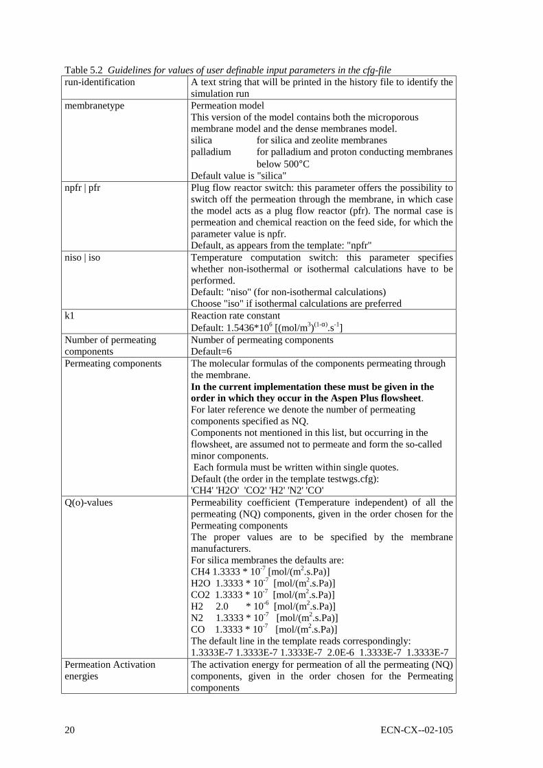
Table 5.2 Guidelines for values of user definable input parameters in the cfg-filerun-identification A text string that will be printed in the history file to identify the
simulation runmembranetype Permeation model
This version of the model contains both the microporousmembrane model and the dense membranes model.silica for silica and zeolite membranespalladium for palladium and proton conducting membranes
below 500°CDefault value is "silica"
npfr | pfr Plug flow reactor switch: this parameter offers the possibility toswitch off the permeation through the membrane, in which casethe model acts as a plug flow reactor (pfr). The normal case ispermeation and chemical reaction on the feed side, for which theparameter value is npfr.Default, as appears from the template: "npfr"
niso | iso Temperature computation switch: this parameter specifieswhether non-isothermal or isothermal calculations have to beperformed.Default: "niso" (for non-isothermal calculations)Choose "iso" if isothermal calculations are preferred
k1 Reaction rate constantDefault: 1.5436*106 [(mol/m3)(1-α).s-1]
Number of permeatingcomponents
Number of permeating componentsDefault=6
Permeating components The molecular formulas of the components permeating throughthe membrane.In the current implementation these must be given in theorder in which they occur in the Aspen Plus flowsheet.For later reference we denote the number of permeatingcomponents specified as NQ.Components not mentioned in this list, but occurring in theflowsheet, are assumed not to permeate and form the so-calledminor components. Each formula must be written within single quotes.Default (the order in the template testwgs.cfg):'CH4' 'H2O' 'CO2' 'H2' 'N2' 'CO'
Q(o)-values Permeability coefficient (Temperature independent) of all thepermeating (NQ) components, given in the order chosen for thePermeating componentsThe proper values are to be specified by the membranemanufacturers.For silica membranes the defaults are:CH4 1.3333 * 10-7 [mol/(m2.s.Pa)]H2O 1.3333 * 10-7 [mol/(m2.s.Pa)]CO2 1.3333 * 10-7 [mol/(m2.s.Pa)]H2 2.0 * 10-6 [mol/(m2.s.Pa)]N2 1.3333 * 10-7 [mol/(m2.s.Pa)]CO 1.3333 * 10-7 [mol/(m2.s.Pa)]The default line in the template reads correspondingly:1.3333E-7 1.3333E-7 1.3333E-7 2.0E-6 1.3333E-7 1.3333E-7
Permeation Activationenergies
The activation energy for permeation of all the permeating (NQ)components, given in the order chosen for the Permeatingcomponents

ECN-CX--02-105 21
The proper values are to be specified by the membranemanufacturers.For silica membranes the defaults are:CH4 0 [kJ/mol]H2O 0 [kJ/mol]CO2 0 [kJ/mol]H2 0 [kJ/mol]N2 0 [kJ/mol]CO 0 [kJ/mol]The default line in the template reads correspondingly:0. 0. 0. 0. 0. 0.
Power in permeationequation
The power coefficient of the partial pressure in the permeationequation of all the permeating (NQ) components, given in theorder chosen for the permeating componentsTHIS LINE IS TO BE ADDED AFTER THEPERMEATION LINE WITH THE ACTIVATIONENERGYTHIS LINE SHOULD ONLY BE PRESENT IN CFG FILESFOR THE PALLADIUM MEMBRANE MODELSThe proper values are to be specified by the membranemanufacturers.For silica membranes this line is not present. For a Palladiummembrane the possible values are:CH4 2 [-]H2O 2 [-]CO2 2 [-]H2 0.88 [-]N2 2 [-]CO 2 [-]The corresponding line in the palladium case file readscorrespondingly:2. 2. 2. 0.88 2. 2.
Reacting components The molecular formulas of the reacting components in the watergas shift reaction.In the current implementation the formulas are prescribed;they must however be given in the order in which they occurin the Aspen Plus flowsheet.The list must mention the required components H2O, CO2, H2and CO, exactly in the order they have been specified in theflowsheet. Each formula must be written within single quotes.Default (the order in the template testwgs.cfg):'H2O' 'CO2' 'H2' 'CO'
Reaction stoichiometriccoefficients
Stoichiometric values for the water gas shift reaction;Do not change these values, but only their order.They must be specified in the order chosen in Reactingcomponents.The values are –1 (for H2O, 1 (for CO2), 1 (for H2), -1 (forCO). The default specification (in the template) reads:-1 1 1 –1
Reaction power lawcoefficients
Specific values for the value of the power low coefficients in thereaction kinetics.Do not change these values, but only their order.These must be specified in the order chosen in Reactingcomponents.

22 ECN-CX--02-105
The values are 0.55 (for H2O, 0.0 (for CO2), 0.0 (for H2), 0.73(for CO). The default specification (in the template) reads:0.55 0.0 0.0 0.73
Heat transfer coefficient (U) The value of the heat transfer coefficientA high value of the heat transfer coefficient could lead to longcomputation times. When encountering long computation timesit is advised to start with a low value and to use the final valuesin the final computations. Default: 250 [W/(m2.K)], Min: 1,Max: 1000
Initial guesses Feed and Sweep outlet (hence: Retentate resp. Permeate) valuesfor mole fractions and temperatures used to start the iterationprocess performed by the NAG-routine D02HAF. The list mustcontain values for all the NQ components whose Q-values aregiven (see: above) and in the order chosen there. Values mustoccur in pairs: the first value of a pair relates to the feed, thesecond one to the sweep. The first NQ pairs serve as initialguesses for variables which represent mole fractions: therefore,if the sum of the supplied values exceed 1, they will berenormalized.One additional pair (number: NQ+1) of initial guesses pertainsto the outlet temperatures (in degrees Kelvin) for the feed andthe sweepDefault: not usedThe testwgs.cfg file does contain a set of initial guesses, as anexample. The set will not be used as long as it is preceded by the[end] header. Removing this particular [end] activates the set.
Table 5.3 Fixed input parameters in the cfg-file
flowtype couiThe current version only allows for countercurrent flowRequired value: coui
transporttype fenThis version deals only with a phenomenological transmembranetransport with a permeation using a measured (temperaturedependent) permeability coefficients times the partial pressuredifferenceRequired value: fen
nreacomp Number of components present in the chemical reaction.Required value: 4
Tref Reference temperature (in degrees Kelvin)Tref is the reference temperature used in the approximation usedfor the specific heat and enthalpy. See cpmeth, further onRequired value: 598.15
aenrgy Activation energy, used in the chemical reaction kineticscomputationsRequired value: 78172.5
cpmeth Selects the method used for the computation of specific heat andStandard Enthalpycpmeth = 0 implies that the following table will be usedValues for specific heat Cp and Standard Enthalpy at STPconditions Ho: Cp HoCO 30.4298 -101.6525*103

ECN-CX--02-105 23
H2O 36.3148 -232.1873*103
CO2 47.1234 -380.8396*103
H2 29.3229 8.7806*103
N2 30.0960 8.9041*103
CH4 36.3600 -76.6525*103
Required value: 0

24 ECN-CX--02-105
ECN-CX--02-105 25
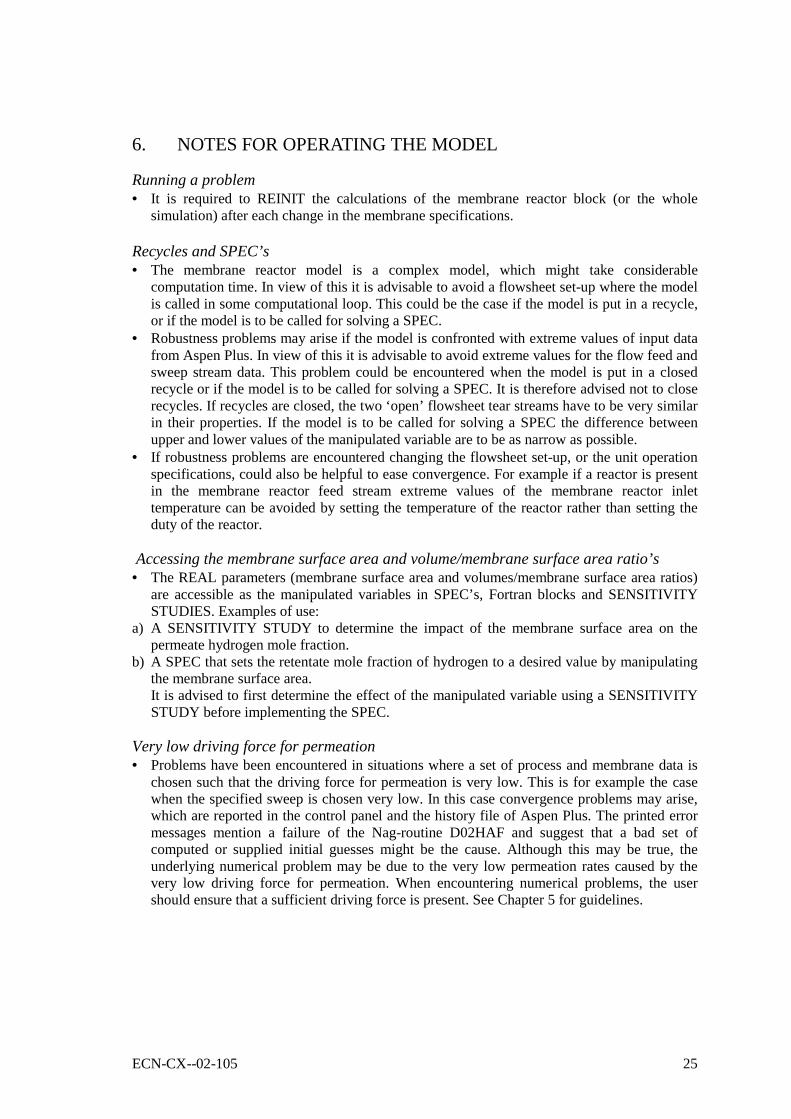
6. NOTES FOR OPERATING THE MODEL
Running a problem• It is required to REINIT the calculations of the membrane reactor block (or the whole
simulation) after each change in the membrane specifications.
Recycles and SPEC’s• The membrane reactor model is a complex model, which might take considerable
computation time. In view of this it is advisable to avoid a flowsheet set-up where the modelis called in some computational loop. This could be the case if the model is put in a recycle,or if the model is to be called for solving a SPEC.
• Robustness problems may arise if the model is confronted with extreme values of input datafrom Aspen Plus. In view of this it is advisable to avoid extreme values for the flow feed andsweep stream data. This problem could be encountered when the model is put in a closedrecycle or if the model is to be called for solving a SPEC. It is therefore advised not to closerecycles. If recycles are closed, the two ‘open’ flowsheet tear streams have to be very similarin their properties. If the model is to be called for solving a SPEC the difference betweenupper and lower values of the manipulated variable are to be as narrow as possible.
• If robustness problems are encountered changing the flowsheet set-up, or the unit operationspecifications, could also be helpful to ease convergence. For example if a reactor is presentin the membrane reactor feed stream extreme values of the membrane reactor inlettemperature can be avoided by setting the temperature of the reactor rather than setting theduty of the reactor.
Accessing the membrane surface area and volume/membrane surface area ratio’s• The REAL parameters (membrane surface area and volumes/membrane surface area ratios)
are accessible as the manipulated variables in SPEC’s, Fortran blocks and SENSITIVITYSTUDIES. Examples of use:
a) A SENSITIVITY STUDY to determine the impact of the membrane surface area on thepermeate hydrogen mole fraction.
b) A SPEC that sets the retentate mole fraction of hydrogen to a desired value by manipulatingthe membrane surface area.It is advised to first determine the effect of the manipulated variable using a SENSITIVITYSTUDY before implementing the SPEC.
Very low driving force for permeation• Problems have been encountered in situations where a set of process and membrane data is
chosen such that the driving force for permeation is very low. This is for example the casewhen the specified sweep is chosen very low. In this case convergence problems may arise,which are reported in the control panel and the history file of Aspen Plus. The printed errormessages mention a failure of the Nag-routine D02HAF and suggest that a bad set ofcomputed or supplied initial guesses might be the cause. Although this may be true, theunderlying numerical problem may be due to the very low permeation rates caused by thevery low driving force for permeation. When encountering numerical problems, the usershould ensure that a sufficient driving force is present. See Chapter 5 for guidelines.

26 ECN-CX--02-105
Initial guesses• The numerical method applied to solve the model equations requires initial guesses for the
flows and temperatures, at both outlets (for feed and sweep). These guesses are determinedas a part of the model computations. In cases where the numerical method doesn't converge -which is reported as a failure of the NAG-routine D02HAF in the control panel and thehistory file - it may be useful to provide the method with external initial guesses. Byinserting a section 'initial guesses' in the cfg-file a user can define his own set of initialguesses.
Long computation timesIt is known that very long computation times can be encountered depending on the value ofsome parameters. An increase from a few seconds to minutes or even several hours has beenobserved. Therefore, when encountering long computation times it is advised to assess thevalues of the following parameters:• The membrane surface area: large membrane surface areas could lead to long computation
times• The sweep flow rate: low sweep flow rates (compared to the feed flow rate) could lead to
long computation times• The sweep temperature: a high difference between sweep and feed stream temperature
difference could lead to long computation times.• The reaction volume/membrane surface area: high values of this ratio could lead to long
computation times. It is advised to determine the value by putting an adiabatic RGIBBSreactor in the permeate stream (or a duplicate stream thereof using a DUPLICATOR). Thevalue of the ratio is sufficiently high if the concentration changes in this reactor are small.
• The heat transfer coefficient: High values of U could lead to long computation times. It isadvised to start with a low value and to use the final values in the final computations
• It is known that due to the usage of powers in the model equations the palladium model mayin some cases require a significant longer computation time than the silica model. When thehydrogen permeability of the Pd membrane is higher, a smaller membrane area can be usedfor the same overall membrane performance, which generally will reduce the computationtime.
ECN-CX--02-105 27
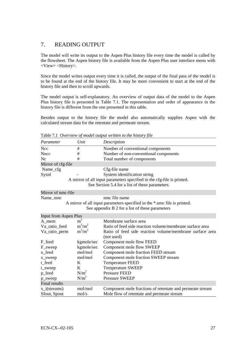
7. READING OUTPUT
The model will write its output to the Aspen Plus history file every time the model is called bythe flowsheet. The Aspen history file is available from the Aspen Plus user interface menu with<View> <History>.
Since the model writes output every time it is called, the output of the final pass of the model isto be found at the end of the history file. It may be more convenient to start at the end of thehistory file and then to scroll upwards.
The model output is self-explanatory. An overview of output data of the model to the AspenPlus history file is presented in Table 7.1. The representation and order of appearance in thehistory file is different from the one presented in this table.
Besides output to the history file the model also automatically supplies Aspen with thecalculated stream data for the retentate and permeate stream.
Table 7.1 Overview of model output written to the history fileParameter Unit DescriptionNcc # Number of conventional componentsNncc # Number of non-conventional componentsNc # Total number of componentsMirror of cfg-file Name_cfg Cfg-file nameSysid - System identification string
A mirror of all input parameters specified in the cfg-file is printed.See Section 5.4 for a list of these parameters
Mirror of nmc-fileName_nmc nmc file name
A mirror of all input parameters specified in the *.nmc file is printed.See appendix B 2 for a list of these parameters
Input from Aspen PlusA_mem m2 Membrane surface areaVa_ratio_feed m3/m2 Ratio of feed side reaction volume/membrane surface areaVa_ratio_perm m3/m2 Ratio of feed side reaction volume/membrane surface area
(not used)F_feed kgmole/sec Component mole flow FEEDF_sweep kgmole/sec Component mole flow SWEEPx_feed mol/mol Component mole fraction FEED streamx_sweep mol/mol Component mole fraction SWEEP streamt_feed K Temperature FEEDt_sweep K Temperature SWEEPp_feed N/m2 Pressure FEEDp_sweep N/m2 Pressure SWEEPFinal resultsx_i(streams) mol/mol Component mole fractions of retentate and permeate streamSfout, Spout mol/s Mole flow of retentate and permeate stream

28 ECN-CX--02-105

ECN-CX--02-105 29
REFERENCES
Delft, Y.C. van, Dijkstra, J.W. (2002): Water Gas Shift Membrane Reactor Model: FunctionalSpecifications, ECN-CX--02-069, Petten, The Netherlands, 2002.

30 ECN-CX--02-105

ECN-CX--02-105 31
APPENDIX A THE CONTENTS OF THE CFG-FILE
Chapter 4 mentions the input parameters in the cfg-file that can be modified by the user, alongwith the remaining fixed parameters. In order to make any changes in the cfg-file it should berealised that the cfg-file has a prescribed structure, with a fixed number of sections, a fixedorder of these sections, and, finally a fixed order of the parameters in the sections. The sectionheaders are specified within square brackets, the first section is the identification section,starting with [ident]. The parameter values for a specific section are specified, separated byblanks, on one line. If the parameter values are numerical the particular line may be terminatedby a #, followed by some explanatory comment.
In Figure A.1 a listing of the contents of the template file testwgs.cfg is given. To modify(permitted parameter) values, users must inspect the contents to find the proper position of theparameter and change the value. It is mandatory to maintain the structure of the file as it is.Actual values may differ from the values given here. The values given are for a water gas shiftmembrane reactor with a microporous (silica) membrane. For other membrane materialsdifferent values of the parameters are to be used.
For the palladium model an extra line is to be inserted after the permeation activation energiesline. This line contains the values of the power law coefficient in the permeation equation: e.g.
2. 2. 2. 0.88 2. 2. # power law coefficient in permeation equation
Figure A.1 The template cgf-file (testwgs.cfg)[ident]Testwgs # run identification string[membranetype]silica # permeation model: silica or palladium[flowtype]coui # flowtype[transporttype]fen # transport type[qfeno] 6 # number of permeating components 'CH4' 'H2O' 'CO2' 'H2' 'N2' 'CO' # permeating components (match order with Aspen)1.3333E-7 1.3333E-7 1.3333E-7 2.0000E-6 1.3333E-7 1.3333E-7 # permeation Q(0)-values0. 0. 0. 0. 0. 0. # permeation activation energies[reaction] 4 # nr. of reacting components nreacomp 'H2O' 'CO2' 'H2' 'CO' # reacting components (match order with Aspen) -1 1 1 -1 # reaction stoichiometric coefficients 0.55 0.0 0.0 0.73 # reaction power law coefficients1.5436E+6 # reaction rate constant k1598.15 # reference temperature Tref78172.5 # reaction activation energy Aenrgynpfr # plug flow reactor switch: npfr or pfrniso # temperature computations switch: niso or iso0 # method selector for Cp/H-computations cpmeth250.0 # heat transfer coefficient U[end] # !! remove [end] to activate guesses[initial guess] # first 6 (having 6 Q-values) mole fractions0.0 0.00.25 0.100.50 0.050.05 0.41

32 ECN-CX--02-105
0.17 0.450.04 0.0070.64815E+03 0.51852E+03 # last pair: outlet temperatures[end]
ECN-CX--02-105 33
APPENDIX B THE CONTENTS OF THE NMC-FILE
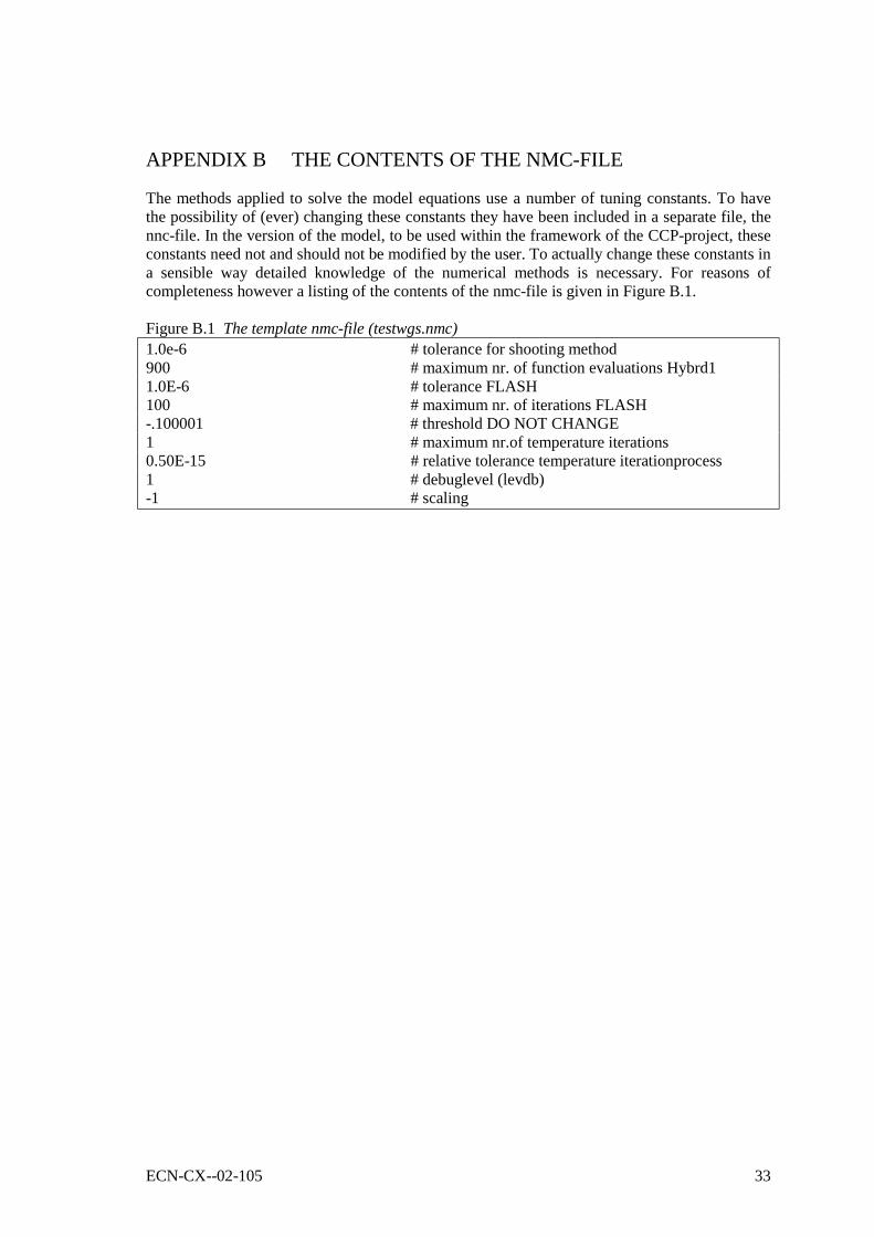
The methods applied to solve the model equations use a number of tuning constants. To havethe possibility of (ever) changing these constants they have been included in a separate file, thennc-file. In the version of the model, to be used within the framework of the CCP-project, theseconstants need not and should not be modified by the user. To actually change these constants ina sensible way detailed knowledge of the numerical methods is necessary. For reasons ofcompleteness however a listing of the contents of the nmc-file is given in Figure B.1.
Figure B.1 The template nmc-file (testwgs.nmc)1.0e-6 # tolerance for shooting method900 # maximum nr. of function evaluations Hybrd11.0E-6 # tolerance FLASH100 # maximum nr. of iterations FLASH-.100001 # threshold DO NOT CHANGE1 # maximum nr.of temperature iterations0.50E-15 # relative tolerance temperature iterationprocess1 # debuglevel (levdb)-1 # scaling