water heater unit - Сайт установщиков · 4d56 diesel 100 2477 validity 2 heater...
TRANSCRIPT

WARNING!
Hazard warning:
Incorrect installation or repair of Webasto heating systems may cause a fire or result in the emission of carbon monoxide, which can be fatal. Serious or fatal injuries can be caused as a result.
Specialist company training, technical documentation, specialized tools and equipment are required to install and repair Webasto heating and cooling systems.
NEVER attempt to install or repair Webasto heating or cooling systems if you have not successfully completed the company training and thereby acquired the required technical skills or if you do not have access to the required technical documentation, tools and equipment needed to carry out correct installation and repairs.
ALWAYS follow all Webasto installation and repair instructions and observe all warning instructions.
Webasto does not accept any liability for defects and damage that are attributable to an installation by untrained staff.
Feel the drive
Mitsubishi L200DieselFrom model year 2006For left-hand drive vehicles only
Ident. No.: 1311019A €10 fee © Webasto AG
Water Heater Unit
Thermo Top E Auxiliary Heating
Thermo Top C Auxiliary Heating
Thermo Top P Auxiliary Heating
e100 0003
e100 0002
e100 0104

22
Mitsubishi L200
Validity
Vehicle and engine types, equipment variants as well as national specifications, which are not listed in these installation instructions, have not been tested. Installation according to these installation instructions may, however, be possible.The installation location of a time switch and summer / winter switch should be confirmed with the end customer before installation.
Manufacturer Model Type EG-BE No. / ABEMitsubishi L200 KA0T L716*00
Engine type Engine Power in kW Engine capacity in cm³4D56 Diesel 100 2477
Validity 2Heater Unit / Installation Kit 3Foreword 3General Instructions 3Special Tools 3Explanatory Notes on the Document 4Preliminary Work 5Heater Unit Installation Location 5Preparing the Electrics 6Electrical Connection 7Manual air conditioning blower control 8
Automatic air conditioning blower control 10Remote Start Option 12Preparing the Installation Location 13Preparing the Heater Unit 14Installing the Heater Unit 15Water Connection 16Combustion Air 19Fuel Connection 20Exhaust System 22Final Work 23Operating instructions for the end customer 23
Table of Contents
33
Mitsubishi L200
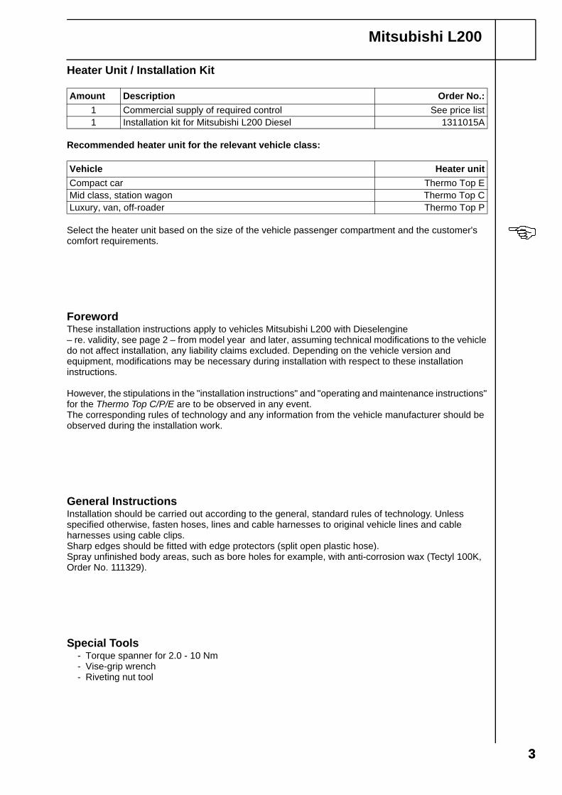
Heater Unit / Installation Kit
Recommended heater unit for the relevant vehicle class:
Select the heater unit based on the size of the vehicle passenger compartment and the customer's comfort requirements.
ForewordThese installation instructions apply to vehicles Mitsubishi L200 with Dieselengine – re. validity, see page 2 – from model year and later, assuming technical modifications to the vehicle do not affect installation, any liability claims excluded. Depending on the vehicle version and equipment, modifications may be necessary during installation with respect to these installation instructions.
However, the stipulations in the "installation instructions" and "operating and maintenance instructions" for the Thermo Top C/P/E are to be observed in any event.The corresponding rules of technology and any information from the vehicle manufacturer should be observed during the installation work.
General InstructionsInstallation should be carried out according to the general, standard rules of technology. Unless specified otherwise, fasten hoses, lines and cable harnesses to original vehicle lines and cable harnesses using cable clips.Sharp edges should be fitted with edge protectors (split open plastic hose).Spray unfinished body areas, such as bore holes for example, with anti-corrosion wax (Tectyl 100K, Order No. 111329).
Special Tools- Torque spanner for 2.0 - 10 Nm- Vise-grip wrench- Riveting nut tool
Amount Description Order No.:1 Commercial supply of required control See price list1 Installation kit for Mitsubishi L200 Diesel 1311015A
Vehicle Heater unitCompact car Thermo Top EMid class, station wagon Thermo Top CLuxury, van, off-roader Thermo Top P

44
Special features are highlighted using the following symbols:
Mechanics
Electrics
Water connection
Fuel connection
Exhaust system
Combustion air
The arrow in the vehicle icon indicates the position on the vehicle and the viewing angle
Mitsubishi L200
Specific risk of injury or fatal accidents
Specific risk of damage to components
Specific risk of fire or explosion
Reference to general installation instructions of Webasto components or to the manufacturer's vehicle-specific documents
Reference to a special technical feature
i
Explanatory Notes on the Document
To provide you with a quick overview of the individual working steps, you will find an identification mark on the outside top right corner of the page in question.

5
Mitsubishi L200
Heater Unit Installation Location
1 Heater unit
Installation location
1
1
Preliminary Work
WARNING!
- Disconnect the battery.- Let off pressure in the cooling system.- Copy the factory number from the original type label to the duplicate type label.- Remove years that do not apply from the duplicate label.- Attach the duplicate label (type label) in the appropriate place.- Completely remove the battery- Open the tank cap, ventilate the tank.- Close the tank cap again.- Remove air conditioning control (only for automatic air conditioning systems)- Remove the footwell panel on the driver and passenger side- Please remove page 23 “Operating instructions for the end customer” and add this to the operating
instructions.

6
Mitsubishi L200
Preparing the Electrics
Only for automatic air conditioning
Wire sections 1, 2 will be needed later forconnecting the 4th fuse.
Cutting wires into sections
Connect with enclosed blade receptaclesaccording to the circuit diagram.Insert wire section 2 in insulating hoses [2x].
Pre-assem-bling the 4th fuse
sw1 2
100
F4 7,5Asw1 sw2
86
85 30
87a87
K3
rt/ws
br rt
swbr

7
Mitsubishi L200
Electrical Connection
Cable harness feed-through
1 Protective rubber sleeve
Summer / winter switch option
1 Summer / winter switch, bore hole Ø 12mm,
Cable harness installation diagram
Fuse holder, K3 relay
1 Original vehicle stay bolts, body washer, bracket 2, original vehicle nut M8
3 Fuse holder4 Bolts M5x16, K3 relay 5, angle bracket, fuse
holder retaining plate, washers, nuts M5
Time switch
1 Time switch
2
1
3
1
rt
sw
br
bl
Wait to install the metering pump cable harness until later together with fuel pipe along the original vehicle fuel lines on the underbody.
i
44
321
5
5
1
8
Mitsubishi L200
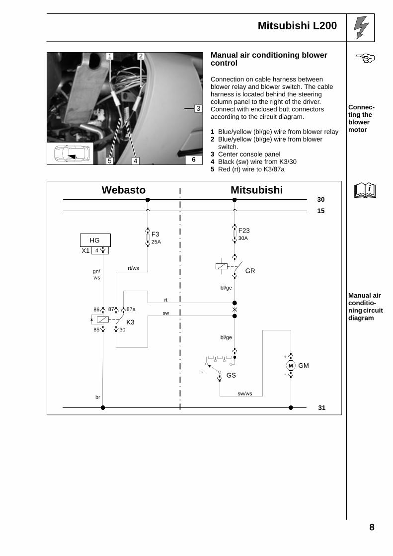
Manual air conditioning blower control
Connection on cable harness between blower relay and blower switch. The cable harness is located behind the steering column panel to the right of the driver.Connect with enclosed butt connectors according to the circuit diagram.
1 Blue/yellow (bl/ge) wire from blower relay 2 Blue/yellow (bl/ge) wire from blower
switch. 3 Center console panel4 Black (sw) wire from K3/305 Red (rt) wire to K3/87a
Connec-ting the blower motor
Manual air conditio-ning circuit diagram
6
1
4
3
2
5
gn/ws
sw
br
rt/ws
Webasto
31
3015
Mitsubishi
rt
bl/ge
86
85 30
87a87
K3
HG4X1
GR
F2330A
F325A
+
-GMM
bl/ge
GS
sw/ws
i
9
Mitsubishi L200
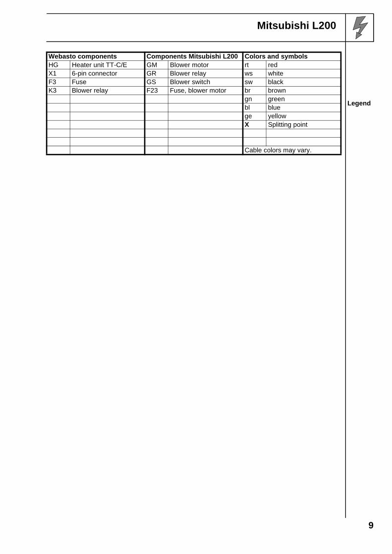
Webasto components Components Mitsubishi L200 Colors and symbols
Legend
HG Heater unit TT-C/E GM Blower motor rt redX1 6-pin connector GR Blower relay ws whiteF3 Fuse GS Blower switch sw blackK3 Blower relay F23 Fuse, blower motor br brown
gn greenbl bluege yellowX Splitting point
Cable colors may vary.
10
Mitsubishi L200
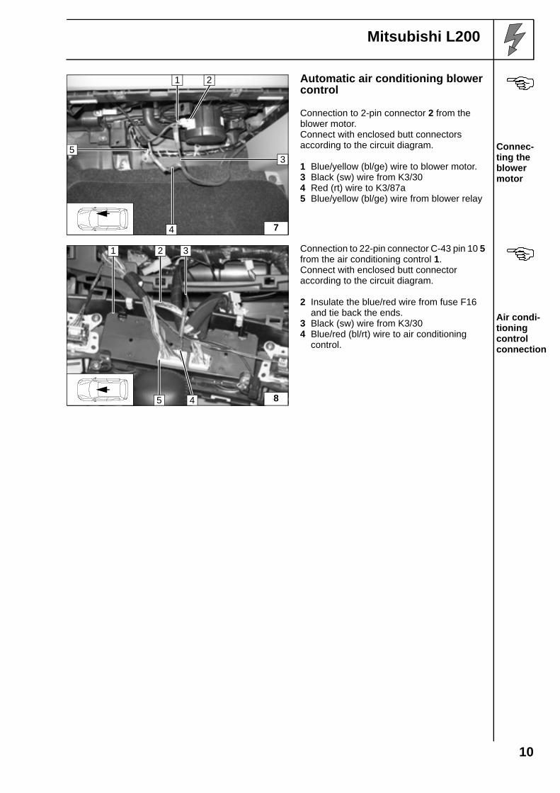
Automatic air conditioning blower control
Connection to 2-pin connector 2 from the blower motor.Connect with enclosed butt connectors according to the circuit diagram.
1 Blue/yellow (bl/ge) wire to blower motor. 3 Black (sw) wire from K3/304 Red (rt) wire to K3/87a5 Blue/yellow (bl/ge) wire from blower relay
Connec-ting the blower motor
Connection to 22-pin connector C-43 pin 10 5 from the air conditioning control 1.Connect with enclosed butt connector according to the circuit diagram.
2 Insulate the blue/red wire from fuse F16 and tie back the ends.
3 Black (sw) wire from K3/304 Blue/red (bl/rt) wire to air conditioning
control.
Air condi-tioning control connection
7
1
4
5
2
3
8
1
5
2 3
4

11
Mitsubishi L200
Automatic air condi-tioning circuit diagram
Webasto components Components Mitsubishi L200 Colors and symbols
Legend
HG Heater unit TT-C/E GM Blower motor rt redX1 6-pin connector GR Blower relay ws whiteF3 Fuse KB Air conditioning control sw blackK3 Blower relay F16 Fuse, air conditioning
controlbr brown
F4 Fuse F23 Fuse GM gn greenSt C- 43 22-pin connector pin 10 bl blue
ge yellowInsulate and tie back wire ends
X Splitting pointCable colors may vary.
Webasto
31
3015
Mitsubishi
F4 7,5A
sw
sw2
86
85 30
87a87
K3
rt/ws
gn/ws
rt
sw
br
HG4X1
F325A
St C-43 10
KB
F167,5A
F2330A
!
bl/rt
bl/ge
bl/ge
bl/rt
GR
+
-GMM
sw/ws
1
i

12
Mitsubishi L200
Remote Start Option
1 Remote start bracket2 Original vehicle bolt, flanged nut M6 (drill
bore hole in the bracket to 7 mm).
3 Remote startAssem-bling the receiver
1 Antenna
Assem-bling the antenna
Temperature sensor for HTM100 only
1 Attach the temperature sensor to the remote start with double-sided adhesive assembly tape
Assem-bling the tempera-ture sensor
1
3
2
9
i
1
10
1
11
13
Mitsubishi L200
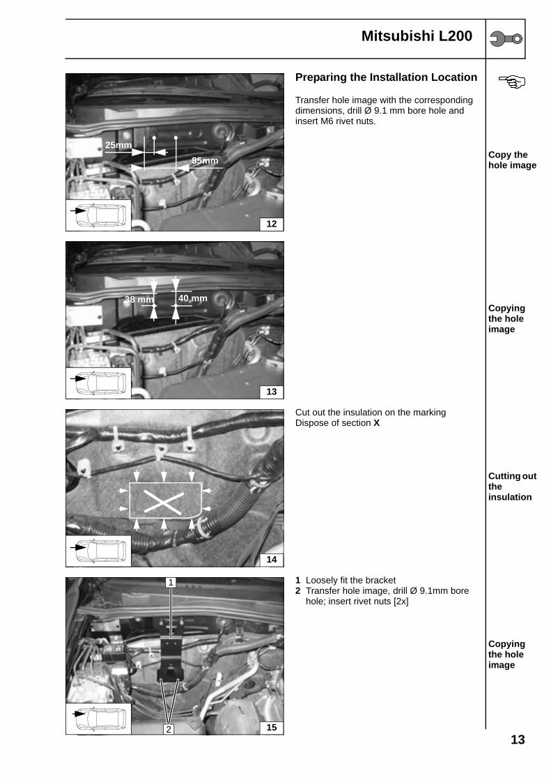
Preparing the Installation Location
Transfer hole image with the corresponding dimensions, drill Ø 9.1 mm bore hole and insert M6 rivet nuts.
Copy the hole image
Copying the hole image
Cut out the insulation on the markingDispose of section X
Cutting out the insulation
1 Loosely fit the bracket2 Transfer hole image, drill Ø 9.1mm bore
hole; insert rivet nuts [2x]
Copying the hole image
12
25mm85mm
13
38 mm 40 mm
14
15
1
2

14
Mitsubishi L200
1 Rivet nuts M6 [4x]
Inserting rivet nuts
Preparing the Heater Unit
Water hose 1 Ø 20mm
c = 140 mm
Dispose of section X Cutting water hose 1 into sections
Assemble hose B und hose C as well as the connecting pipe 2.
1 Heater unit2 Connecting pipe 18x20 [2x]
Pre-assem-bling water hose 1 on the heater unit
Ejot screw bolts tightening torque 10 Nm!
1 Bracket2 Ejot screw bolt [3x]3 Hose section, Ø 10 mm hose clamps [2x]4 Mecanyl fuel line Pre-
assem-bling the bracket and fuel on the heater unit
16
1
1
c
CX X
B
B
2
17
C 1
2
18
1 2
2
4
3

15
Mitsubishi L200
1 M6x20 bolt [2x], spring washer [2x]2 30 mm long spacer [2x], bolt protector [2x]
Pre-assem-bling the bolts on the bracket
Installing the Heater Unit
First, loosely fit the pre-assembled bolts 1.
Assem-bling the heater unit
1 M6x35 bolt [2x], spring washer [2x], 20 mm spacer [2x]
When finished, tighten all bolt connections.
Assem-bling the heater unit
19
1
2
20
1
21
1 1

16
Mitsubishi L200
Water Connection
WARNING!Tighten all hose clamps with 2.0 + 0.5 Nm.Any coolant running off should be collected using an appropriate container!Install hoses so that they are kink-free. Unless specified otherwise, always fasten using cable clips. Position hose clamps and spring band clamps so that no other hose can be damaged.The connection should be "inline" based on the following diagram:
Water installation diagram
All undesignated clamps are Ø 20-27 mm hose clamps.All connecting pipes 1= Ø 18x20 and all connecting pipes 2 = Ø 18x18.
Heatexchanger
Motor
AB
C
D
1
1
2

17
Mitsubishi L200
a = 800 mmb = 440 mm
Dispose of section X
Cutting water hose 2 into sections
1 Disassemble original vehicle hose from the engine outlet to the heat exchanger inlet.
(The clamp from the heat exchanger inlet will be used again.)
Splitting point
1 Original vehicle hose from the engine outlet to the heat exchanger inlet.
2 Splitting points [2x]3 Dispose of sections4 Required heat exchanger inlet moulded
hose
Cutting the hose
1 Original vehicle hose to the heat exchanger inlet
Pre-assem-bling the hose
a d
A
X
D
X
22
1
23
1 2
20mm
3
3
4
24
D
1

18
Mitsubishi L200
Before installing the water hoses in the engine compartment, install the two cable harnesses 1, 2 according to the illustration.
Connec-ting to the heater unit
Fasten the water hoses to original vehicle cable harness with cable clips 1. Ensure sufficient distance to the engine.
Installing in the engine compart-ment
Before connecting, fill the water hoses with coolant.
1 Engine outlet connecting piece
Connec-ting to the engine outlet
Before connecting, fill the water hoses with coolant.
1 Original vehicle clamp2 Pre-assembled heat exchanger inlet hose
Connec-ting to the heat exchanger inlet
25
D
A
21
26
B
A
1
1
27
A1
28
D 1
2

19
Mitsubishi L200
Combustion Air
1 Combustion air intake pipe2 Ø 27 mm hose clamp
Assem-ling the vacuum line
1 Combustion air intake silencer2 Cable clip
Assem-bling the silencer
29
1
2
i
30
1
2

20
Mitsubishi L200
Fuel Connection
CAUTION!Open the vehicle's tank-cap lock, ventilate the tank and then re-close the tank lock.
Catch any fuel running off with an appropriate container.
Install fuel line and metering pump cable harness so that they are protected against stone impact. Unless specified otherwise, always fasten using cable clips.Fit the fuel line and cable harness with edge protectors around sharp edges.
WARNING!The fuel line and cable harness to the metering pump should be installed based on the cable harness installation diagram.
Install the Mecanyl fuel pipe 1 in the tube shaft 2 on the right side of the vehicle.
Installing wires
Install the Mecanyl fuel pipe 1 together with the metering pump cable harness to the installation location of the metering pump along the original vehicle fuel lines.
Installing wires
Note the installation position of the metering pump, see the Installation Instructions.Installation location is to the right next to the vehicle tank.Fuel line from the heater unit on the pressure side of the metering pump [side with connector].
1 Fastening strap with holes2 Original vehicle bolt M83 Silentblock, flanged nut M6 to fastening
strap with holes4 Rubberized tube clamp; flanged nut M6 to
silentblock
Metering pump installation location
31
1 2
32
1
33
3
1
4
2 i

21
Mitsubishi L200
Fuel line from the fuel extractor on the intake side of the metering pump [side without connector].Check the position of the components; adjust if necessary. Check that these rotate freely.
3 Fuel line with metering pump cable harness to original vehicle fuel lines
2 Hose section, Ø 10 mm hose clamps [2x]1 Connector housing
Connec-ting to the metering pump
Loosen the fuel tank and lower it to the front.
3 Separate the leading fuel line about 150 mm before the tank mounting
2 Fuel extractor 12x5x121 Spring band clamp Ø22 mm4 Residual section of Mecanyl fuel line5 90° moulded hose, Ø10 mm hose clamps
[2x] Install fuel take-off
Fuel line from the fuel extractor on the intake side of the metering pump [side without connector].Check the position of the components; adjust if necessary. Check that these rotate freely.
1 Residual section of Mecanyl fuel line2 Hose section, Ø 10 mm hose clamps [2x] Connec-
ting to the metering pump
34
3
1 2
35
1 1
5
4
2 3
36
1 2

Mitsubishi L200
Webasto AGPostfach 80 - 82132 Stockdorf - Hotline 0 18 05 / 93 22 78Hotfax (0395) 55 92-353 - http://www.webasto.de
Feel the drive
Exhaust System
1 Exhaust pipea = 580mm
2 Exhaust end sectionb = 130mm
Dispose of section X
Preparing the exhaust pipe
1 Hose clamp 2 Exhaust pipe
Assem-bling the exhaust pipe
When installing the exhaust pipe 1, ensure sufficient distance from adjacent components.
Assem-bling the exhaust pipe
a b
1 2
X
1
2 37
1
38
Printed in Germany 04/06Printed by: Steffen

2323
Mitsubishi L200
Ensure sufficient distance from adjacent components.
1 Hose clamp [2x]2 Silencer, bolt M6x20, flanged nut M6 to
angle bracket.3 Exhaust end section4 Angle bracket5 Available bore hole, rivet nut, bolt M6x20,
spring washer, body washer, angle bracket6 Exhaust pipe
Assem-bling the silencer
Final Work
WARNING!Reassemble disassembled components in reverse order.Check that all hose lines, hose, spring band clamps and universal clips, and all electrical connections are securely fastened.Secure all loose lines using cable clip.Only use manufacturer-approved coolant. Spray heating unit components with anti-corrosion wax (Tectyl 100K, Order No. 111329).
- Connect battery.- Start engine, bleed coolant circuit according to the vehicle manufacturer's specifications, top up
with coolant.- Set the time switch.- Set the manual air conditioning or automatic air conditioning according to the "operating
instructions for the end customer". - Check that the auxiliary heating operates properly, see operating instructions / installation
instructions.- Attach the "Switch off auxiliary heating before re-fuelling" sticker onto the left side of the B-pillar.
Operating instructions for the end customerPlease remove page and add to the vehicle operating instructions.
Before parking the vehicle, make the following settings:
1 Air outlet to windscreen2 Blower set to level "1" or "2"3 Temperature to "max."
For vehicles with manual air conditio-ning
1 Air outlet to windscreen2 Blower rpm to 1/3 of the max. rpm3 Temperature to "max."
For vehicles with
394
1 2
5
1
3
6
i
40
1 2
3
1 2