water-methanol injection systems · pdf file4 97651 v.7.0 water-methanol injection...
TRANSCRIPT

01/28/16 PN 97651 V.7.0
Banks Straight-Shot® & Double-Shot®
Water-Methanol
Injection Systems Vehicle Specific Applications
THIS MANUAL IS FOR USE WITH SYSTEMS 45150, 45151, 45155, 45156, 45160, 45161, 45170, 45171, 45175, 45176, 45180, 45181
Gale Banks Engineering 546 Duggan Avenue • Azusa, CA 91702 (626) 969-9600 • Fax (626) 334-1743
Product Information & Sales: (800) 438-7693Customer Support: (888) 839-5600 Installation Support: (888) 839-2700
bankspower.com
©2016 Gale Banks Engineering
Owner’sManualwith Installation Instructions
2 97651 v.7.0
General Installation PracticesTo avoid serious injury or death, follow the safety information in this document.
1. For ease of installation of your Water-Methanol injection system, famil-iarize yourself with the procedure by reading the entire manual before start-ing work. This instruction manual con-tains 28 pages of text, illustrations and parts listing.
2. Disconnect the ground cable from the battery before beginning work. If there are two batteries, disconnect both.
3. Route and tie wires and hoses a min-imum of 6 inches away from exhaust heat, moving parts and sharp edges. Clearance of 8 inches or more is recom-mended where possible.
4. When raising the vehicle, support it on properly weight-rated safety stands, ramps or a commercial hoist. Follow the manufacturer’s safety precautions. Take care to balance the vehicle to prevent it from slipping or falling. When using ramps, be sure the front wheels
are centered squarely on the topsides; put the transmission in park; set the hand brake; and place blocks behind the rear wheels.
: Do not use floor jacks to support the vehicle while working under it. Do not raise the vehicle onto concrete blocks, masonry or any other item not intended specifically for this use.
5. During installation, keep your work area and components clean to avoid pos-sible dirt entry into the engine.
6. For proper performance from your Water-Methanol injection system and to prevent engine damage, it is essential that your engine’s fuel system be capable of delivering fuel at the factory’s specifica-tion. We have often found vehicles with inadequate low pressure side fuel deliv-ery that isn’t apparent until performance modifications are made.
Definitions of ANSI Z535 Safety Standards
: Indicate[s] a hazard-ous situation which, if not avoided, will result in death or serious injury.
: Indicate[s] a hazard-ous situation which, if not avoided, could result in death or serious injury.
: Indicate[s] a hazard-ous situation which, if not avoided, could result in mild or moderate injury.
: Indicate[s] a situation that requires your immediate attention.
Dear Customer,
If you have any questions concerning the installation of your Banks Straight-Shot® or
Double-Shot® system, please call our Technical Service Hotline at (888) 839-2700 between 7:00 am and 4:00 pm (PT). If you have any questions relating to shipping or billing, please contact our Customer Service Department at (888) 839-5600.
Thank you.

97651 v.7.0 3
Tools Required:• 1⁄4” and 3⁄8” drive ratchets
• Inch and metric sockets and 3⁄8” drive extension
• Inch and metric combination or open-end wrenches
• Standard and Phillips head screwdrivers
• Standard and needle-nose pliers
• Pocket or X-Acto knife
• Clean shop towels or rags
• Inch-pound or foot-pound torque wrench
• Electric or pneumatic drill
• Compressed air source and hoses or extension cords
• 1/4”, 11/32”, and 7/16” drill bits
• 1/8”-27 NPT and 1/4”-18 NPT taps
• Tap handle or equivalent
• Volt meter or multi-meter
• Eye and ear protection
• Permanent marker
Highly recommended tools and supplies:
• Penetrating oil or light lubricant spray
• Center punch and hammer
• Deburr tool
• Compressed air nozzle
Table of ContentsGeneral Installation Practices . . . . 2
Tools Required. . . . . . . . . . . . . . . . 3
Water-Methanol Injection Introduction and Safety . . . . . . . . 4
Banks Water-Methanol Injection System Installation . . . . . . . . . . . . 4 Windshield Washer Reservoir. . 4 Water-Methanol Tank . . . . . . . . 5 Injection Pump . . . . . . . . . . . . . 6 Solenoid . . . . . . . . . . . . . . . . . . . 7 Injection Nozzles . . . . . . . . . . . . 8 Plumbing (Straight-Shot®) . . . . 12 Plumbing (Double-Shot®). . . . . 13 EGT Thermocouple . . . . . . . . . 13 Injection Controller . . . . . . . . . 14 Wiring. . . . . . . . . . . . . . . . . . . . 15 MAP/TPS Signal Intercept Harness . . . . . . . . . . 18
Injection Controller Menus Flow Chart . . . . . . . . . . . . 16
System Setup and Testing . . . . . 19
Test Drive. . . . . . . . . . . . . . . . . . . 25
System Tuning and Nozzle Selection . . . . . . . . . . . . . 26
Parts list . . . . . . . . . . . . . . . . . . . . 27
Appendix A Nozzle Flow Rates . . . . . . . . . . . . . . . . 28
Appendix B Pump Flow Rates . . . . . . . . . . . . . . . . 28
Appendix C Error Codes & Trouble Shooting . . . . . 28
Appendix D Common Key-on Power Fuse Locations . . . . . . . . . . . . . . . . . . . 29
4 97651 v.7.0
Water-Methanol Injection Introduction and SafetyBanks Water-Methanol injection systems are a reliable and cost effective way to increase power and fuel economy while decreasing exhaust gas temperatures (EGT).
Banks Straight-Shot provides everything you will need for safe and effective Water-Methanol injection. Banks Straight-Shot utilizes your vehicle’s windshield washer reservoir as the Water-Methanol tank to save space and reduce cost. Banks Straight-Shot is a fully programmable, sin-gle stage injection system that provides a direct shot of Water-Methanol through one or two injection nozzles.
Banks Double-Shot adds second stage injection capabilities controlled by a sole-noid. Increased injection control results in increased power and/or fuel economy. Banks Double-Shot also includes a large capacity tank to increase time between fills and accommodates the increased flow volume of two to three nozzles.
Pure methanol is a flammable and vol-atile fuel, however when diluted with water as in Banks PowerBlend, the mix-ture becomes much safer. Avoid direct contact with methanol, pure or diluted. If contact with skin occurs, wash contact area thoroughly.
Banks Water-Methanol Injection System InstallationYou have been provided with a limit-ed length of 1/4” diameter nylon tubing (P/N 45140) to plumb your Banks Water-Methanol injection system, take care while determining the location of system components. If needed, extra nylon tubing can be purchased from Banks Power by calling (800) 601-8077.
Take care while determining the location of Water-Methanol injection components that require power and/or signal as the wire lengths of the wire harness were designed for components mounted in the engine compartment.
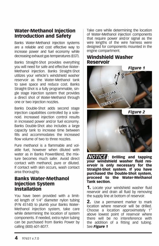
Windshield Washer Reservoir
: Drilling and tapping your windshield washer fluid res-ervoir is only necessary for the Straight-Shot system. If you have purchased the Double-Shot system, proceed to the Water-Methanol Tank section.
1. Locate your windshield washer fluid reservoir and drain all fluid by removing the supply line at bottom of reservoir.
2. Use a permanent marker to mark location where reservoir will be drilled. Choose a location approximately 1” above lowest point of reservoir where there will be no intereference with the addition of a fitting and tubing. See Figure 1
Figure 1
Figure 2
97651 v.7.0 5
3. Remove windshield washer fluid reser-voir from vehicle for better access when drilling and tapping.
4. Use a center punch to mark the hole location and keep the drill bit from wan-dering. Use 7/16” drill bit to drill a hole at marked location. Drill perpendicular to reservoir surface to avoid leaks.
5. Use 1/4”-18 NPT tap to thread wind-shield washer fluid reservoir. Ensure tap is perpendicular to reservoir surface to avoid leaks. Check the thread depth as you tap by periodically removing the tap and screwing the 90º male push-lock (P/N 45121) fitting into the tapped hole. The fit-ting should thread in 3 to 31⁄2 turns hand tight. Do not install the fitting in place at this time.
: Running the tap too deeply can prevent fitting from properly sealing.
6. Thoroughly clean inside of reservoir to remove all debris.
7. Thread 90-degree male Push-Lock fitting into reservoir. Tighten 2-3 turns past hand tight. Do not over tighten. See Figure 2
8. Add enough water in reservoir to check for leaks around fitting. Drain water and reinstall windshield washer fluid res-ervoir.
Water-Methanol Tank: A large capacity tank
(P/N 45095-45098) is only provided in the Double-Shot system. Proceed to the Injection Pump section if you purchased the Straight-Shot system.
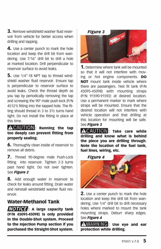
1. Determine where tank will be mounted so that it will not interfere with mov-ing or hot engine components. DO NOT mount tank inside vehicle where there are passengers. Test fit tank (P/N 45095-45098) with mounting straps (P/N 91590-91592) at desired location. Use a permanent marker to mark where straps will be mounted. Ensure that the desired location will not interfere with vehicle operation and that drilling at this location for mounting will be safe. See Figure 3
: Take care while drilling and know what is behind the piece you are drilling through. Note the location of the fuel tank, fuel lines, wiring, etc.
2. Use a center punch to mark the hole location and keep the drill bit from wan-dering. Use 1/4” drill bit to drill necessary holes where marked to mount the tank mounting straps. Deburr sharp edges. See Figure 4
: Use eye and ear protection while drilling.
Figure 3
Figure 4

6 97651 v.7.0
3. Thread 90-degree male Push-Lock fit-ting (P/N 45121) into threaded bung of tank. Tighten 2-3 turns past hand tight.Do not over tighten. Add enough water in reservoir to check for leaks around fitting. See Figure 5
4. Drain water and use provided mount-ing straps, bolts (P/N 91120), nuts (P/N 91110), and washers (P/N 91103) to mount tank where desired. See Figure 6
Injection Pump: Injection pump (P/N
45030 or 45031) can be mounted in any orientation, but is flow directional. The head unit is labeled with an arrow to show flow direction. Take care while determining the mount-ing location in your vehicle.See Figure 7
1. Determine where pump will be mount-ed so that it will not interfere with mov-ing or hot engine components and will avoid spray and debris from tires. Use pump bracket as a template to mark where bracket will be mounted. Ensure that the desired location will not interfere with vehicle operation and that drilling at this location for mounting will be safe. See Figure 8
: Take care while drilling and know what is behind the piece you are drilling through. Note the location of the fuel tank, fuel lines, wiring, etc.
2. Use a center punch to mark the hole locations and keep the drill bit from wan-dering. Use a 1/4” drill bit to drill the necessary holes where marked to mount pump bracket. Deburr sharp edges.
: Use eye and ear protection while drilling.
Figure 6
Figure 7
Figure 9
Figure 8
Figure 5

97651 v.7.0 7
3. Use provided bolts (P/N 91761), nuts (P/N 91771), and washers (P/N 91102) to mount pump in your truck. Tighten until nylon locking feature is fully engaged and rubber grommet is compressed at least 1/8.” Do not over tighten or damage to grommets will occur. See Figure 9
Solenoid: A solenoid (P/N 45035)
is only provided in the Double-Shot system. Proceed to the Injection Nozzle(s) section if you purchased the Straight-Shot system.
: Solenoid must be mounted upright and is flow direc-tional with the ports labeled “IN” and “OUT”. Take care while deter-mining the mounting position in your vehicle. See Figures 10 and 11.
1. Determine where the solenoid will be mounted so that it will not inter-fere with moving or hot engine com-ponents and will avoid spray and debris from tires. Use solenoid brack-et (P/N 45038) as a template to mark
where the bracket will be mounted. Ensure that the desired location will not interfere with vehicle operation and that drilling at this location for mounting will be safe. See Figure 12
: Take care while drilling and know what is behind the piece you are drilling through. Note the location of the fuel tank, fuel lines, wiring, etc.
2. Use a center punch to mark the hole location and keep the drill bit from wan-dering. Use a 1/4” drill bit to drill nec-essary holes where marked to mount solenoid bracket. Deburr sharp edges. See Figure 13
: Use eye and ear protection while drilling.
Figure 10
Figure 12
Figure 11Figure 13
8 97651 v.7.0
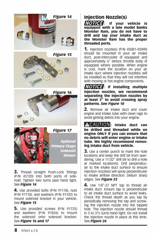
3. Thread straight Push-Lock fittings (P/N 45120) into both ports of sole-noid. Tighten two turns past hand tight. See Figure 14
4. Use provided bolts (P/N 91118), nuts (P/N 91110), and washers (P/N 91102) to mount solenoid bracket in your vehicle. See Figure 15
5. Use provided screws (P/N 91725) and washers (P/N 91826) to mount the solenoid onto solenoid bracket. See Figure 16 and 17
Injection Nozzle(s): If your vehicle is
equipped with a late model Banks Monster Ram, you do not have to drill and tap your intake duct as the Monster Ram has the proper threaded ports.
1. Injection nozzle(s) (P/N 45081-45090) should be mounted in your air intake duct, post-intercooler (if equipped) and approximately 6” before throttle body (if equipped) where possible. When engine is cool, mark the location on your air intake duct where injection nozzle(s) will be installed so that they will not interfere with moving or hot engine components.
: If installing multiple injection nozzles, we recommend separating the injection nozzles by at least 3” to avoid crossing spray patterns. See Figure 18
2. Remove air intake duct and cover engine and intake tube with clean rags to avoid getting debris into your engine.
: Intake duct can be drilled and threaded while on engine ONLY if you can ensure that no debris will enter engine or intake tube. We highly recommend remov-ing intake duct from vehicle.
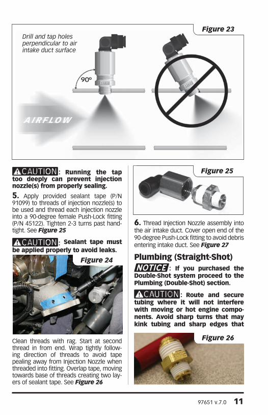
3. Use a center punch to mark the hole locations and keep the drill bit from wan-dering. Use a 11/32” drill bit to drill a hole at marked location(s). Drill perpendicu-lar to the intake duct surface to ensure injection nozzle(s) will spray perpendicular to intake airflow direction. Deburr sharp edges. See Figure 23
4. Use 1/8”-27 NPT tap to thread air intake duct. Ensure tap is perpendicular to air intake duct surface to avoid leaks. Check the thread depth as you tap by periodically removing the tap and screw-ing the injection nozzle into the tapped hole. The injection nozzle should thread in 3 to 31⁄2 turns hand tight. Do not install the injection nozzle in place at this time. See Figure 24
Figure 14
Figure 15
Figure 16
Figure 17
Optional Primary Stage
Solenoid Shown
97651 v.7.0 9
ThrottleBody
ThrottleBody
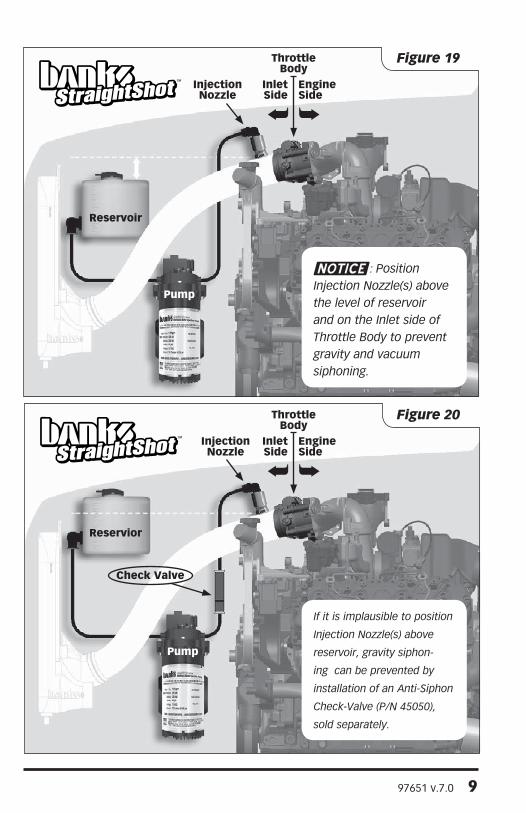
EngineSide
EngineSide
Inlet Side
Inlet Side
InjectionNozzle
InjectionNozzle
Check Valve
Reservoir
Reservior
: Position Injection Nozzle(s) above the level of reservoir and on the Inlet side of Throttle Body to prevent gravity and vacuum siphoning.
If it is implausible to position
Injection Nozzle(s) above
reservoir, gravity siphon-
ing can be prevented by
installation of an Anti-Siphon
Check-Valve (P/N 45050),
sold separately.
Pump
Pump
Figure 19
Figure 20

10 97651 v.7.0
ThrottleBody
ThrottleBody
EngineSide
Inlet Side
InjectionNozzle
InjectionNozzle
InjectionNozzle
Solenoid
Check Valve
Solenoid
“Y” Fitting
Reservoir
Reservoir
If it is implausible to posi-
tion Injection Nozzle(s) on
inlet side of Throttle Body,
vacuum siphoning can be
prevented by installation of
an Anti-Siphon Solenoid (P/N
45035), sold separately.
Double-Shot system shown: with check valve for first stage nozzle pre-throttle body, high-flow solenoid for second stage nozzle(s) post-throttle body. Pre-throttle body mounting for all nozzles preferred but not required with solenoid-controlled stages.
Pump
Pump
Figure 21
Figure 22
97651 v.7.0 11
: Running the tap too deeply can prevent injection nozzle(s) from properly sealing.
5. Apply provided sealant tape (P/N 91099) to threads of injection nozzle(s) to be used and thread each injection nozzle into a 90-degree female Push-Lock fitting (P/N 45122). Tighten 2-3 turns past hand-tight. See Figure 25
: Sealant tape must be applied properly to avoid leaks.
Clean threads with rag. Start at second thread in from end. Wrap tightly follow-ing direction of threads to avoid tape pealing away from Injection Nozzle when threaded into fitting. Overlap tape, moving towards base of threads creating two lay-ers of sealant tape. See Figure 26
6. Thread Injection Nozzle assembly into the air intake duct. Cover open end of the 90-degree Push-Lock fitting to avoid debris entering intake duct. See Figure 27
Plumbing (Straight-Shot): If you purchased the
Double-Shot system proceed to the Plumbing (Double-Shot) section.
: Route and secure tubing where it will not interfere with moving or hot engine compo-nents. Avoid sharp turns that may kink tubing and sharp edges that
Figure 26
Figure 25
Figure 24
Figure 23Drill and tap holes perpendicular to air intake duct surface

12 97651 v.7.0
may damage tubing.
: Cut tubing using a Pocket or X-Acto knife to avoid pinching the tubing. Pinching the tubing will cause it to not seat properly.
1. Secure one end of 1/4” Nylon tub-ing (P/N 45140) into Push-Lock fitting on windshield washer fluid reservoir by firmly pushing tubing into Push-Lock fitting.
Carefully pull on tubing to ensure tubing is secured properly.
2. Route tubing to injection pump inlet. Cut tubing, allowing approximately 1/2” for securing into injection pump. Properly secure tubing into injection pump inlet. See Figure 28
: Make all cuts as square as possible to avoid leaks.
3. For a single injection nozzle, secure and route tubing from pump outlet to injection nozzle assembly in intake duct. Properly cut tubing and secure into injec-tion nozzle assembly.
4. For two injection nozzles, secure and route tubing from pump outlet to port #1 of “Y” fitting (P/N 45123). Properly cut tubing and secure into “Y” fitting. See Figure 29
: Determine where you want Push-Lock “Y” fitting located and route tubing appropriately. Choose a location that is easily accessible and can be checked for leaks.
4a. Secure tubing in port #2 of “Y” fitting and route tubing to first injection nozzle assembly. Properly cut tubing and secure into injection nozzle assembly.
4b. Repeat step 4a for second injection nozzle assembly using port #3 on the “Y” fitting.
5. Use tie wraps to secure all tubing.
Plumbing (Double-Shot): Route and secure tub-
ing where it will not interfere with moving or hot engine components. Avoid sharp turns that may kink tubing and sharp edges that may damage tubing.
: Cut tubing using
Figure 28
Figure 27
Figure 29

97651 v.7.0 13
a Pocket or X-Acto knife to avoid pinching the tubing. Pinching the tubing will cause it to not seat properly.
1. Secure one end of 1/4” Nylon tubing (P/N 45140) into Push-Lock fitting on high capacity tank by firmly pushing tubing into Push-Lock fitting. Carefully pull on tubing to ensure tubing is secured properly.
2. Route tubing to injection pump inlet. Cut tubing, allowing approximately 1/2” for securing into injection pump. Properly secure tubing into injection pump inlet.
: Make all cuts as square as possible to avoid leaks.
3. Route tubing from injection pump out-let to port #1 of “Y” fitting (P/N 45123). Properly cut tubing and secure into “Y” fitting. See Figure 29
4. Secure tubing in port #2 of “Y” fitting and route tubing to inlet of check valve. Properly cut and secure tubing in Push-Lock check valve. See Figure 30
5. Secure tubing in port #3 of “Y” fitting and route tubing to “IN” port of solenoid. Properly cut and secure tubing in Push-Lock on solenoid.
6. Secure tubing in outlet of check valve and route to the first injection nozzle assembly. Properly cut tubing and secure into injection nozzle assembly.
7. For two injection nozzles, secure tub-ing in Push-Lock fitting of solenoid labeled “OUT” and route to the second injection nozzle assembly. Properly cut tubing and secure into injection nozzle assembly.
8. For three injection nozzles, secure tubing in Push-Lock fitting of solenoid labeled “OUT” and route to port #1 of “Y” fitting (P/N 45123). Properly cut tubing and secure in “Y” fitting. Secure tubing in port #2 of “Y” fitting and route tubing to the second injection nozzle assembly. Properly cut tubing and secure into injec-tion nozzle assembly. Repeat for the third injection nozzle assembly using the #3 port of the “Y” fitting.
EGT Thermocouple: An EGT thermocouple (P/N
63042) is only provided in the Double-Shot system. If you purchased the Straight-Shot system, proceed to the Wiring and Controller section. See Figure 31
1. The thermocouple monitors the tem-perature of the exhaust gases entering the turbocharger at the turbine housing. Installation requires that the exhaust man-ifold be drilled near the manifold outlet. It is recommended that the manifold be removed from the engine to thoroughly clean out all metal chips from drilling. All metal shavings must be cleaned from the manifold to avoid turbine wheel damage.
2. Mark location on exhaust manifold (pre-turbo) where EGT thermocouple will be mounted so that it will not interfere with any engine components.
3. Remove exhaust manifold and cover the exhaust ports and up-pipe to avoid debris entering engine or exhaust system.
4. Drill a 7⁄16” hole in exhaust manifold at marked location perpendicular to manifold surface. Deburr sharp edges.
5. Tap the hole for a 1⁄4” NPT thread. Check the thread depth as you tap by periodically removing the tap and screwing the pipe
Figure 30

14 97651 v.7.0
coupling into the tapped hole. The coupling should thread in 3 to 31⁄2 turns hand tight. Do not install the probe in place at this time.
: Running the tap too deeply can prevent the pipe fitting from properly sealing.
6. Thoroughly clean exhaust manifold with solvent to remove any debris and reinstall exhaust manifold on engine.
: Failure to remove all metal chips could result in cata-strophic damage to the turbocharg-er’s turbine wheel.
7. Remove the NPT fitting from the ther-mocouple and install it on the exhaust manifold. Use supplied anti-seize lubricant on the threads and torque to 14–16 lb-ft.
8. Reinstall the exhaust manifold. Apply anti-seize lubricant to the manifold bolt threads and torque as specified in service manual.
9. Install thermocouple in fitting on exhaust manifold. See Figure 32
Injection Controller: A basic mounting panel
is provided to mount injection con-
troller. Other mounting options, including A-pillar pod mounts, are available through Banks Power for vehicle specific mounting. See Figure 33
1. Determine where the injection control-ler (P/N 45020 or 45021) will be mounted using mounting panel (P/N 63001) and controller bracket (P/N 63006) where it will not interfere with driving operations.
: Take care when installing the mounting panel as to not damage anything critical with fasteners.
2. Install the mounting panel using sup-plied fasteners.
3. Install injection controller in mounting panel and secure using controller bracket.
Wiring: Route and secure wir-
ing where it will not interfere with moving or hot engine components (along OEM wiring where possible). Avoid sharp edges that may damage wiring.
1. Using provided system schematics, find connectors for injection controller on the pump harness (P/N 62831) and signal harness (P/N 62832). Carefully feed these connectors and boost reference hose (P/N 94445) through firewall grommet (usually located underneath dash) to injection con-troller. See Figure 34
Figure 31
Figure 32

97651 v.7.0 15
2. Connect both 8-pin connectors to controller where appropriate. Connect 2-pin connector for EGT thermocouple, if equipped. See Figure 35
3. Secure boost reference hose to refer-ence port barb on back of injection con-troller using the 3/32” hose (P/N 94118) as an adapter between the boost reference hose and the reference port barb. See Figure 36
4. Route appropriate connectors of sig-nal harness to respective Water-Methanol injection components and fasten connec-tors. Use provided system schematics for reference. Secure wiring with tie wraps.
5. Route appropriate connectors of pump harness to respective Water-Methanol injection components and fasten connec-tors. Use provided system schematics for reference. Secure wiring with tie wraps.
6. Use the provided list of fuse locations (Appendix D, pg. 29) or a multimeter to find a fuse with key-on power for the injection controller. Connect the fuse tap for the injection controller. See Figures 38 & 39
7. Fasten all other connectors and termi-nals (power supplies, ground leads, etc.) of pump and signal harnesses to appropriate locations, using system schematics for reference. Secure wiring with tie wraps.
Figure 33 Figure 34
Figure 35
Figure 36
Figure 39
Figure 38

16 97651 v.7.0
Inje
ctio
n C
on
tro
ller
Men
us
Flo
w C
har
t
Input Dependent Main Menu Section
OC
TL
DIS
P
LED
INP
T
MA
P
PRES
SM
EN
U
B1
BD
C1
T1 TDC
1
Qu
ick
-On
/Off
Pre
ssin
g t
he
se
lect
bu
tto
n, a
ny
tim
e t
he
inje
cti
on
sys
tem
is e
nab
led
an
d t
he
co
ntr
olle
r is
in d
isp
lay
mo
de,
will
tu
rn t
he
ou
tpu
t co
ntr
ol t
o
off
dis
ab
ling t
he
inje
cti
on
sys
tem
. Pre
ssin
g t
he
se
lect
bu
tto
n a
gain
will
re
turn
th
e o
utp
ut
co
ntr
ol t
o t
he
pre
vio
us
sett
ing e
nab
ling t
he
inje
cti
on
sys
tem
usi
ng t
he
pre
vio
usl
y sa
ved
co
ntr
ol p
oin
ts .

97651 v.7.0 17
BX -
BOO
ST R
EFER
ENC
E VA
LUE
X
BDC
X -
BOO
ST D
UTY
CYC
LE X
BST
– BO
OST
D5.
9 - D
OD
GE
5.9L
D6.
7 - D
OD
GE
6.7L
DIS
P –
DIS
PLAY
E+B
- EG
T A
ND
BO
OST
E+T
- EG
T A
ND
TH
ROTT
LE
EDC
X -
EGT
DU
TY C
YCLE
X
EGT
- EX
HA
UST
GA
S TE
MPE
RATU
RE
EGTX
- EG
T RE
FERE
NC
E VA
LUE
X
F6.0
- FO
RD 6
.0L
F6.4
- FO
RD 6
.4L
INPT
– IN
PUT
INT
– IN
TERN
AL
MA
P - M
AN
IFO
LD A
BSO
LUTE
PRE
SSU
RE
OC
TL -
OU
TPU
T C
ON
TRO
L
PDC
- PU
MP
DU
TY C
YCLE
S2ST
- SO
LEN
OID
#2
STAT
US
TX –
TH
ROTT
LE R
EFER
ENC
E VA
LUE
X
TDC
X –
TH
ROTT
LE D
UTY
CYC
LE X
THRT
– T
HRO
TTLE
VER
- VER
SIO
N
Set d
esire
d va
lue
usin
g m
enu
butt
on to
scr
oll
and
sele
ct b
utto
n to
m
ake
sele
ctio
n.
Mai
n m
enu
optio
ns a
re B
OLD
.
Inpu
t dep
ende
nt m
ain
men
u se
lect
ion
disp
lays
“B
” if
MA
P is
sel
ecte
d fo
r in
put
(def
ault)
and
“T”
if T
HR
T is
sel
ecte
d fo
r in
put.
OP
TIO
NS
E__
_ w
ill o
nly
disp
lay
if eq
uipp
ed w
ith E
GT
ther
moc
oupl
e.
OP
TIO
NS
___
3 an
d __
_4 w
ill o
nly
disp
lay
if eq
uipp
ed w
ith s
econ
dary
sol
enoi
d.
Set d
esire
d va
lue
usin
g m
enu
butt
on to
scr
oll
and
sele
ct b
utto
n to
m
ake
sele
ctio
n.Input Dependent Main Menu Section
BD
C1
B2
BD
C2
B3
BD
C3
B4
BD
C4
TDC
1
T2 TDC
2
T3 TDC
3
T4 TDC
4
PRES
SM
EN
UPR
ESS
ME
NU
PRES
SSE
LEC
T
EGT1
EDC
1
EGT2
EDC
2
EGT3
EDC
3
EGT4
EDC
4
VE
R(V
ER
SIO
N)
PRES
SM
ENU
PRES
SSE
LEC
T
VER

18 97651 v.7.0
MAP/TPS Signal Intercept Harness
: A vehicle specific MAP/TPS signal intercept harness (pigtail harness) is only included in vehi-cle specific methanol-water injec-tion systems. If you purchased a universal methanol-water injection system, proceed to the System Testing and Setup section. Based on the desired injection controller input (boost or throttle), the MAP or TPS signal must be intercepted and sent to injection controller. For boost based systems, the MAP sig-nal must be intercepted. For throttle based systems, the TPS signal must be intercepted.
Certain supported vehicles use the OEM MAP or TPS sensor with a pigtail harness to intercept the desired signal.
For supported vehicles:
1. Locate the MAP or TPS sensor on your vehicle, depending on the desired input mode. Disconnect the OEM wire har-ness by releasing locking mechanism. A small standard screwdriver can be used to release locking mechanism, if necessary. See Figure 40
2. Connect pigtail harness (See Parts List for P/Ns) to MAP or TPS sensor and check for full engagement of locking mechanism. See Figure 41
3. Connect OEM wire harness to pigtail harness and check for full engagement of locking mechanism. See Figure 42
4. Connect 1-pin male connector to the blue lead of signal harness and check for full engagement of locking mecha-nism. See system schematic for reference. See Figure 43
: Route and secure wiring where it will not interfere with mov-ing or hot engine components (along
OEM wiring where possible). Avoid sharp edges that may damage wiring.
System Testing and Setup: Use “MENU” button on
injection controller to scroll through a menu and “SELECT” button to choose a menu option. See injection control-
Figure 40
Figure 41
Figure 42
Figure 43

97651 v.7.0 19
ler menu flow chart (pages 16-17) for an overview of controller menus.
: This section of the manual will walk you through the initial purging and pressure test pro-cess to ensure that your installation is clean and leak-free. It is critical to safe system operation that each step be followed in order, and that any leaks are corrected before vehicle operation.
1. Fill windshield washer fluid reservoir or high capacity tank with distilled water.
2. Turn vehicle ignition to on without start-ing the vehicle. The injection controller screen should light up and scroll “BANKS POWER” along with the controller software version number.
3. Remove tubing from each injection nozzle assembly by pressing in the collar of the push-lock fitting and gently pulling
on tubing. Place end(s) of tubing into a clear container of suitable size (the high volume pump can move more than a gallon of water a minute) and secure con-tainer in a stable position.
: Tubing must be disconnected from injection nozzle assembly while priming pump, oth-erwise water could flood and dam-age engine.
4. Temporarily disconnect the pump pres-sure switch connector from the signal harness, or remove one pump pressure switch lead from the pump. Now, the sys-tem may be primed and purged by using the injection controller’s “TEST” mode. To activate “TEST” mode:
4a. Scroll through the main menu by pressing the “MENU” button. Press the “SELECT” button to select the “OCTL” (output control) sub-menu.
4b. Scroll through the “OCTL” sub-menu by pressing the “MENU” button. Press the
“SELECT” button to select and activate “TEST” mode. Any connected solenoids will open, the pump will turn on and run at 50% duty cycle for 6 seconds, and then turn off automatically. Let the test mode run until water flows out of tubing into clear container, and then turn it off by selecting “OFF” from the “OCTL” menu.
4c. If there is debris present in the con-tainer after running the initial test, re-fill the system tank with clean distilled water and repeat “TEST” mode until all debris remaining from installation has been purged from the system. Check all tubing connections for leaks.
: If the controller dis-plays an error code, or the pump does not turn on when activating “TEST” mode, refer to the error code index (page 27) and use system schematic (P/N 97650-A or 97651-A) to ensure all components were connected to appropriate connec-tors. Check all connectors for full engagement. If pump turns on, but water does not flow out of tubing, use system schematic (P/N 97650-A or 97651-A) to ensure system was plumbed correctly.
4d. Remove all injector nozzle(s) from their mounting ports on the engine and re-connect them to their supply tubes. Empty water from the clear container used in the previous step, insert the assembled injector nozzles and supply lines back into the container and re-secure in a stable position.
4e. Initiate another “TEST” mode from the injection controller and examine the spray pattern from each nozzle. A clean, evenly-distributed spray cone should be visible from every nozzle (some moderate pulsation is normal and will vary based on nozzle selection). Examine the threaded joint between each nozzle and nozzle holder carefully for any leaks during this high pressure test - tighten the assembly
20 97651 v.7.0
in quarter turn steps until corrected.
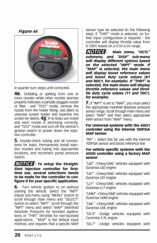
4e. Dribbling or spitting from one or more nozzles while other nozzles atomize properly indicates a partially plugged nozzle or filter - exit “TEST” mode, remove the nozzle from the holder fitting. Use pliers to unscrew screen holder and examine the screen for debris. 4g. If no leaks are noted and each nozzle is atomizing correctly, exit “TEST” mode and turn off the vehicle’s ignition switch to power down the injec-tion controller.
5. Double-check tubing and all connec-tions for leaks. Permanently install injec-tion nozzles and tubing into appropriate locations, and reconnect pump pressure switch.
: To setup the Straight-Shot injection controller for first-time use, several selections needs to be made for the controller to con-figure it for your specific application.
6. Turn vehicle ignition to on without starting the vehicle. Select the “INPT” (input) sub-menu using “MENU” button to scroll through main menu and “SELECT” button to select “INPT”. Scroll through the “INPT” menu and select “MAP” (Manifold Absolute Pressure) for boosted applica-tions or “THRT” (throttle) for non-boosted applications. “MAP” is the default input method, and requires that a specific MAP
sensor type be selected (in the following step). If “THRT” mode is selected, no fur-ther input configuration is required - the controller will display throttle value from 0-100% based on a 0.5V-4.5V range.
: Main menu, “OCTL” submenu, and “DISP” sub-menu will display different options based on the selected “INPT” mode. If “MAP” is selected, the main menu will display boost reference values and boost duty cycle values (B1 and BDC1, for example). If “THRT” is selected, the main menu will display throttle reference values and throt-tle duty cycle values (T1 and TDC1, for example).
7. If “INPT” is set to “MAP”, you must select the appropriate manifold absolute pressure sensor range. Scroll through main menu and select “MAP” and then select appropriate MAP sensor from “MAP” menu.
For Universal systems with the 45021 controller using the internal 100PSIA MAP sensor:
“INT” – Select this for use with the internal 100PSIA sensor and boost reference line
For vehicle specific systems with the 45020 controller using a factory MAP sensor:
“LBZ” –Chevy/GMC vehicles equipped with Duramax LBZ engine
“LB7” –Chevy/GMC vehicles equipped with Duramax LB7 engine
“LLY” –Chevy/GMC vehicles equipped with Duramax LLY engine
“LMM” –Chevy/GMC vehicles equipped with Duramax LMM engine
“LML” –Chevy/GMC vehicles equipped with Duramax LML engine
“D5.9” –Dodge vehicles equipped with Cummins 5.9L engine
“D6.7” –Dodge vehicles equipped with
Figure 44

97651 v.7.0 21
Cummins 6.7L engine
“F6.0” –Ford vehicles equipped with Powerstroke 6.0L engine
“F6.4” –Ford vehicles equipped with Powerstroke 6.4L engine
8. Turn on your water-methanol system by scrolling through main menu and selecting “OCTL”. Select desired control method from “OCTL” menu. See injection controller menu flow chart for menu structure.
“OFF” – Turns water-methanol injection sys-tem off (gauge features will still function)
“BST” – Controls system using boost pres-sure (Boosted applications only)
“THRT” – Controls system using percent throttle opening (Non-boosted applications only)
“EGT” – Controls system using exhaust gas temperature (Must be equipped with EGT thermocouple)
“E+B” – Controls system using exhaust gas temperature and boost pressure (Boosted applications only)
“E+T” – Controls system using exhaust gas temperature and percent throttle opening. (Non-boosted applications only)
“TEST” – Opens any connected solenoids and tests for system pressure,automatically turns pump off and closes solenoids when system reaches 40 PSI. If pump pressure switch is disconnected or 40 PSI output pressure switch point is not exceeded, pump will run at 50% duty cycle for 6 sec-onds with all solenoids open.
: When using any control method based on controlling EGT, injecting distilled water only is rec-ommended as a mixture with even a moderate methanol percentage can increase EGT at high injection rates.
9. Set desired display parameter by selecting “DISP” from main menu and then selecting desired display option.
“BST” – Displays manifold pressure in PSI (Boosted applications only)
“THRT” – Displays percent open throttle (Non-boosted applications only)
“EGT” – Displays exhaust gas temperature in degrees Fahrenheit (If equipped with EGT thermocouple)
“PDC” – Displays pump duty cycle in per-cent.
“S2ST” – Displays solenoid #2 status as on or off (If equipped with secondary solenoid)
10. Turn the injection activity LED on or off by selecting “LED” from main menu and then selecting “ON” or “OFF”. When “ON”, the Alert LED will flash with a fre-quency that corresponds to pump duty cycle when pump is running. When “OFF”, the LED will not flash to indicate injection activity, but will still function normally to indicate any system errors.
11. To turn water-methanol system off, select “OCTL” from main menu and then select “OFF” from the “OCTL” menu.
Your injection system will now operate with the default setpoint values. To tai-lor the system’s activation points and injection quantity to your specific engine, please refer to the advanced tuning sec-tion (below).
Advanced Tuning
The Banks Straight-Shot and Double-Shot injection systems offer a wide working injection flow range, as well as a wide range of user-selectable setpoints to con-trol injection by. The goal of these wide flow- and adjustment ranges are to match a progressively increasing amount of injec-tion to your engine’s air-, load-, or EGT-curve. To vary injection quantity across a fixed size injection nozzle, supply pressure to the nozzle must be varied (as opposed to a typical automotive fuel injector, which uses a fixed supply pressure, and varies injection rate by switching the injector on
22 97651 v.7.0
and off rapidly).
The Straight-Shot and Double-Shot sys-tems vary supply pressure by increasing the duty cycle supplied to the injection pump. A low duty cycle supplies mini-mal power to the pump, and creates a low output pressure. Increasing the duty cycle increases the power supplied to the pump, generating an increased output pressure (and increased flow across the injection nozzle). Flow across the nozzle does not increase linearly with pressure, however - the injection controller and the injection pump compensate for this to a degree. To learn more, and view full nozzle flow and pump capacity curves, please visit our webpage at http://www.bankspower.com/straightshot
12. Set the first reference value (B1 or T1) to control when pump will turn on and first duty cycle value (BDC1 or TDC1) to control pump duty cycle at the first reference value. For boosted vehicles, reference values are boost pressure in PSI. For non-boosted vehicles, reference values are percent open throttle where 0 is closed throttle and 100 is wide open throttle.
12a. Scroll through main menu and select “B1” or “T1”, depending on your application. Scroll through the values and select the reference value that you want the pump to turn on. If configuring a StraightShot system with only one injection stage, this setpoint should be above your tyical light-load boost / throttle value. For DoubleShot systems where a small injection quantity is desired at light load, this should be set several PSI (or %) below your typical light-load boost / throttle value. The default setting is 10 PSI, which should be changed to a much higher setting (50% or more) if configuring a throttle-based system.
12b. Scroll through main menu and select “BDC1” or “TDC1”, depending on your appli-cation. Scroll through the values and select the percentage of pump duty cycle at which the pump will run once triggered by the
first reference value. The default setting is 30% duty cycle - if this value is set too low, with too large of a nozzle, it can cause a low initial pump output pressure which can result in improper atomization at the nozzle. This may also trigger a Pump Output Error code if the 40 PSI pump output pressure switch is not triggered. However, if this value is set too high, the initial output pressure spike and injection ‘hit’ can be too severe and cause the engine to bog or misfire.
13. Repeat step 12 to set remain-ing reference values and accompanying duty cycle percentage values.
: Straight-Shot systems have two reference values with accompanying duty cycle values. Double-Shot systems have four ref-erence values with accompanying duty cycle values.
EXAMPLE: For boosted applications, your water-methanol injection system will be inactive until boost pressure reaches the first boost reference value (B1), at which value first injection noz-zle (or nozzle set) will begin to spray with a volumetric flow rate based on the first duty cycle value (BDC1). This injection nozzle (or injection nozzle set) will continue to spray while flow rate increases (with increasing pump duty cycle) until boost pressure reaches the second boost reference value (B2). At this value, the pump duty cycle will equal that of the second duty cycle (BDC2) percentage, and will remain at this duty cycle if boost continues to rise. Similarly, for Double-Shot systems the second injection nozzle (or second injection nozzle set) will begin spraying once boost pressure reaches B3 with a pump duty cycle equal to BDC3. Flow rate will increase until boost pressure reaches B4, at which value the pump duty cycle will equal that of BDC4.
For non-boosted applications, your

97651 v.7.0 23

24 97651 v.7.0

97651 v.7.0 25
water-methanol injection system will be inactive until percent throttle opening reaches the first throttle reference value (T1), at which value first injection nozzle (or injection nozzle set) will begin to spray with a volumetric flow rate based on the first duty cycle value (TDC1) . This injection nozzle (or injection nozzle set) will continue to spray while flow rate increases (with increasing pump duty cycle) until throttle opening reaches the second throttle reference value (T2). At this value, the pump duty cycle will equal that of the second duty cycle (TDC2) percentage, and will remain at this duty cycle if throttle percentage continues to rise. Similarly, for Double-Shot systems the second injection nozzle (or second injection nozzle set) will begin spraying once throttle opening reaches T3 with a pump duty cycle equal to TDC3. Flow rate will increase until throttle opening reaches T4, at which value the pump duty cycle will equal that of TDC4. Note that DC stays constant past T4 setpoint.
Test Drive1. Drain water from windshield washer fluid reservoir or high capacity tank. Fill with Banks PowerBlend injection fluid.
2. Start vehicle and allow it to reach operating temperature before driving.
3. Ensure the Water-Methanol injection system is turned on (see System Setup and Testing, step 8).
4. Set injection controller to display pump duty cycle (see System Setup and Testing, step 9) to check if pump is run-ning during driving conditions.
5. Drive normally in a minimal traffic area where you can safely monitor the injection controller. Once boost pres-sure reaches the first boost reference point, the injection controller should display the first pump duty cycle (BDC1). Pump duty cycle should increase as boost pressure increases, until boost
pressure reaches the second boost ref-erence point (B2).
If injection controller only displays zero for pump duty cycle, the pump is not turning on. Ensure system is turned on. There may be an issue with the wiring or setup. Check all connections and check system setup on injection controller.
6. Park vehicle in a safe location and check for any leaks in Water-Methanol injection system.
System Tuning and Nozzle SelectionThe Straight-Shot and Double-Shot sys-tems come pre-packaged with several different nozzle options that cover a wide range of applications, but some controller setting optimization may help dial in your system for your intended usage.
When configuring for maximum perfor-mance, the largest kitted nozzles should be installed. If engine hesitation, misfir-ing, or early ignition (excessive combus-tion noise or rattling) is experienced, reduction of the commanded pump duty cycle, along with raising the boost refer-ence points will reduce the injection quantity to help reduce this. If required, reduce the nozzle size to make large changes in injection quantity.
If typical fluid consumption is higher than desired, increase the initial boost reference point to decrease the fre-quency with which the controller acti-vates (turning on only at higher load).
If more frequent injection is desired (for instance, when combating a constant high-EGT condition with distilled water, or offsetting diesel fuel usage with a water-methanol mixture), a proportion-ally small jet should be used, with a reduced initial boost reference point and low starting and final pump duty cycle values (a ‘flat’ response curve).

26 97651 v.7.0

97651 v.7.0 27
Parts List

28 97651 v.7.0
BANKS PN GAL / HR LB / HR* CC / MIN GAS (SUPPORTED) DIESEL (ADDED)*45030 43.7 327 2757 1250 17545031 23.3 175 1470 750 90
Appendix B: Pump Flow Rates FLOW RATE @ 100 PSI ΔP HORSEPOWER POTENTIAL
*BASED ON A 50/50 MIX OF METHANOL AND WATER
BANKS DESCRIPTIONPmp Assy, High Volume, Water-‐Methanol Inj.Pmp Assy, Low Volume, Water-‐Methanol Inj.
ERROR CODE DESCRIPTION TROUBLESHOOT
MAP ERR1 MAP sensor signal voltage too low or high Check sensor connecBon and harness leads for shorts or broken connecBons. Refer to system schemaBc (P/N 97650-‐A or 97651-‐A).
SOL ERR2 Solenoid (either primary or 2nd stage) control current too high
Check solenoid harness connecBons and leads for shorts to ground. Refer to system schemaBc (P/N 97650-‐A or 97651-‐A).
FLD ERR3 Pump output pressure switch error
Typical indicaBon of low / out of fluid state, check and fill reservoir. If condiBon does not correct, check connecBon and harness leads for shorts or broken connecBons. Refer to system schemaBc (P/N 97650-‐A or 97651-‐A). If no
connecBon errors found, inspect downstream fluid plumbing from pump for leaks. If no leaks found, increase starBng pump duty cycle to a higher value, as inadequate line pressure (<40 PSI) to trigger the pump output pressure switch
may be present -‐ common with larger nozzle(s).
EGT ERR4 EGT sensor connecBon problemCheck sensor connecBon and harness leads for shorts or broken connecBons.
Refer to system schemaBc (P/N 97650-‐A or 97651-‐A).
STAT ERR5System Status output line connecBon
problemCheck harness connecBon and leads for shorts to ground. Refer to system
schemaBc (P/N 97650-‐A or 97651-‐A).
PUMP ERR6 Pump overcurrent problem Check pump harness connecBon and leads for shorts to ground. Refer to system schemaBc (P/N 97650-‐A or 97651-‐A).
Appendix C: Error Codes & Trouble Shoo6ng
Parts List (Continued)

97651 v.7.0 29
Installation Notes

30 97651 v.7.0
Installation Notes

97651 v.7.0 31
Installation Notes

32 97651 v.7.0
Gale Banks Engineering 546 Duggan Avenue • Azusa, CA 91702 (626) 969-9600 • Fax (626) 334-1743
Product Information & Sales: (800) 438-7693Customer Support: (888) 839-5600 Installation Support: (888) 839-2700
bankspower.com