water sensitive urban design guidelines wollondilly shire
TRANSCRIPT

WSUD Guidelines || Wollondilly Shire Council || November 2020
Page 1 of 47
Water Sensitive Urban Design Guidelines
Wollondilly Shire Council
November 2020

WSUD Guidelines || Wollondilly Shire Council || November 2020
Page 2 of 47
Document Management
Version Date ID Authors
1 - Draft 17 June 2019 2018-52-D26 Ralf Pfleiderer & Rob Catchlove
2 – Updated draft (without graphics)
11 February 2020 2018-52-D48 Ralf Pfleiderer & Rob Catchlove
3 – Final 27 February 2020 2018-52-D50 Ralf Pfleiderer & Rob Catchlove
3 – Final with updated species 10 March 2020 2018-52-D51 Ralf Pfleiderer & Rob Catchlove
4 – New cover photo 27 April 2020 2018-52-D59 Ralf Pfleiderer & Rob Catchlove
5 – Including precinct image 4 January 2021 2018-52-D61 Ralf Pfleiderer & Rob Catchlove
Disclaimer
This document may not be used for purposes other than those for which it is compiled. While every care has been taken
to compile this report, Wave Consulting Australia Pty Ltd accept no liability whatsoever for any loss (including without
limitation direct or indirect loss and any loss of profit, data or economic loss) occasioned to any person nor for any damage,
cost, claim or expense arising from reliance on this report or any of its content.

WSUD Guidelines || Wollondilly Shire Council || November 2020
Page 3 of 47
Table of Contents
1 Introduction 5
2 Context 5
2.1 Wollondilly Vision 5
2.2 Risk based framework 6
2.3 Regional planning perspective 6
2.4 Vision for water 6
3 Principles of integrated water management 7
4 Integrated water objectives and targets 9
4.1 Zero impact 9
4.2 Requirements 9 4.2.1 Residential 9 4.2.2 Industrial and commercial 10
4.3 Subdivisions 11
4.4 Water demand baseline and targets 12
4.5 Stormwater runoff baseline and targets 12
5 Treatment train 13
6 What defines a high performing and successful WSUD asset? 13
7 IWM options 14
7.1 Options and types of development 14
7.2 Technical references 14
7.3 Rainwater tanks 15
7.4 Swales 17
7.5 Bioretention / raingardens 19
7.6 Tree pits 21
7.7 Infiltration trenches 23
7.8 Constructed wetlands and sediment ponds 25
7.9 Fixtures and water efficient options 28
8 Planning, design, & construction process 29
8.1 Works Adjacent Waterways 29
8.2 Early Planning – knowing your site and your requirements 29
8.3 Concept Design – objective of and submission to council requirements 30
8.4 Submission of the Concept Design 27
8.5 Detailed Design 27
8.6 Submission of the detailed design 28

WSUD Guidelines || Wollondilly Shire Council || November 2020
Page 4 of 47
8.7 Sediment control during construction 28
8.8 Construction and maintenance 28
8.9 Construction Phase – Inspection of WSUD Assets 29
8.10 Works as Executed (WAE) Drawings & Compliance Certificates 29
8.11 Defect liability period 29
8.12 Signage 30
8.13 Handover of WSUD Assets 30
9 Construction and maintenance 31
10 References 32
11 Attachments 34
11.1 Attachment 1 - Development Application Checklist (lodged with DA) 34
11.2 Attachment 2 - Construction Certificate Application Checklist (lodged with CC) 36
11.3 Attachment 3 – MUSIC parameters 37
11.4 Attachment 4 – Plant species and densities 38 11.4.1 Swales 38 11.4.2 Raingardens and bioretention basin 38 11.4.3 Constructed wetlands, sediment basins and ponds 38 11.4.4 Core functional plant species 39

WSUD Guidelines || Wollondilly Shire Council || November 2020
Page 5 of 47
1 Introduction
Water Sensitive Urban Design (WSUD) integrates urban water cycle management with urban planning and
design, with the aim of mimicking natural systems to minimise negative impacts on the natural water cycle
and receiving waterways. It offers an alternative to the traditional conveyance approach to stormwater
management by managing water at its source, and thereby reducing the impact of urban development on
waterways and required size of the downstream stormwater infrastructure network. It seeks to minimise the
influence of impervious surfaces on waterways, reuse water on site, incorporate retention basins to reduce
peak flows, and incorporate treatment systems to remove pollutants from impacting on waterways.
The key principles of WSUD are:
a. Protect and enhance natural water systems within urban environments.
b. Integrate stormwater treatment into the landscape, maximising the visual and recreational amenity of developments.
c. Improve the quality of water draining from urban developments into receiving environments.
d. Reduce runoff and peak flows from urban developments by increasing local detention times and minimising impervious areas.
e. Minimise drainage infrastructure costs of development due to reduced runoff and peak flows.
Reducing the impact of stormwater run-off is particularly important in Wollondilly Shire Council, which has
swimmable creeks and rivers with icon species such as the platypus and the koala living in or near them, and
two endangered species: Sydney Hawk Dragonfly and the Macquarie Perch. Uncontrolled, business as usual
stormwater discharge will do irreparable harm to these natural ecosystems that takes orders of magnitude
more investment to repair.
This document should be read in conjunction with the Wollondilly Water Strategy (2020) and Wollondilly
Water Policy (2020).
2 Context
2.1 Wollondilly Vision
Wollondilly Shire Council has a mission statement “To create opportunities in partnership with the community
and to enhance quality of life and the environment, by managing growth and providing sustainable services
and facilities1.”
Another strategic document that outlines Wollondilly’s intention towards water management is the 2017
Community Strategic Plan (CSP). The CSP expresses the aspirations held by the community of Wollondilly and
sets strategies for achieving those aspirations. The CSP ‘Create Wollondilly 2033’ contains five distinct themes:
Sustainable and Balanced Growth
Management and Provision of Infrastructure
Caring for the Environment
Looking after the Community
Efficient and Effective Council.
1 https://www.wollondilly.nsw.gov.au/council/about-us-2/

WSUD Guidelines || Wollondilly Shire Council || November 2020
Page 6 of 47
The two CSP strategies noted below provide a clear mandate to design and maintain WSUD assets to protect
and maintain the environment.
Strategy EN1 – Protect and enhance biodiversity, waterways and groundwater.
o Maintain and enhance the condition of biodiversity including the condition of water sources
(both surface and groundwater).
Strategy EN2 – Protect the environment from development pressures.
o Contribute to development to achieve positive environmental, social and economic outcomes
2.2 Risk based framework
The vision is consistent with the State Government policy objectives to adopt a risk based framework
2.3 Regional planning perspective
From a regional perspective, the Greater Sydney Commission has outlined the vision of the region and link
between urban development and water and sustainability initiatives.
The vision for Greater Sydney as a metropolis of three cities – the Western Parkland City, the Central River City
and the Eastern Harbour City and a 30-minute city – means residents in the Western City District will have
quicker and easier access to a wider range of jobs, housing types and activities. This vision will improve the
District’s lifestyle and environmental assets 2 . The District Plan’s planning priorities and actions include
infrastructure and collaboration, liveability, productivity, sustainability and implementation. These
synchronise well with Create Wollondilly Community Strategic Plan 2033.
Delivering on this vision, within WSC LGA, means creating liveable sustainable townships, particularly within
the Wilton development.
2.4 Vision for water
Wollondilly’s vision for water, taken from the Wollondilly Shire Council’s Integrated Water Management
Strategy, is to maintain our pristine creeks and rivers to be swimmable and ecologically rich and diverse.
This requires that new development has zero impact on the waterways with no extra stormwater runoff
entering the waterways (compared to natural environments) and wastewater being treated and reused.
Maintaining pristine waterways will:
Maintain a healthy and diverse ecosystem of plants, animals and insects.
Maintain good water quality for in stream health and for downstream water supply
Allow for direct contact recreation such as swimming
Maintain or enhance vegetation buffer corridors either side of waterways to prevent erosion and
provide a robust buffer strip to support all waterway values
2 https://www.greater.sydney/western-city-district-plan

WSUD Guidelines || Wollondilly Shire Council || November 2020
Page 7 of 47
3 Principles of integrated water management
Sustainable and integrated water management is based on minimising the impact of developments on the
water cycle. This requires evaluation of all elements of the water cycle and how they impact the environment.
Principles of IWM include:
Minimising impervious areas (roads, roof and pavements)
Maximising healthy green vegetation and soil to improve infiltration and water retention
Capture retain, reuse and/or treat any run-off from impervious area as high in the catchment as
possible (i.e. rainwater tanks and median strip swales)
Maximise reuse of captured water to reduce potable water consumption and discharge off site
Ensure wastewater is treated and reuse onsite or via centralised system that does not discharge to
the local waterway
Protect groundwaters from extraction that is not replenished at the same rate. Replenishment must
be of a suitable quality and rate to maintain the groundwater resource for future generations.
The flow and volume of stormwater is the biggest contributor to waterway degradation, in addition to the
pollutants commonly found in stormwater. Therefore, retaining as much as possible stormwater on lot or
within the catchment is the primary aim. Retention should be maximised through the following suite of
actions;
Minimise impermeable area and ensure green areas have good to high infiltration capacity.
Maximise the size of rainwater tanks for each building as well as the demand to internal uses and
irrigation. An empty tank is a good tank to ensure maximum capture of the next rain event.
Include a leaking outlet for tanks that do not have a large internal use such a commercial or office
building with only daytime, toilet demand.
Infiltrate overflow and leaking outlets from tanks as well as any other on lot runoff into on lot
infiltration or absorption trench systems.
Connection of road run-off to central median swales or other treatment system to infiltrate and treat
off-lot runoff.
Include an end of line system where required to retain and treat any remaining run-off.
Consider stormwater harvesting systems where there is a suitable demand (open space irrigation or
commercial/industrial use) that can utilise the water.
By retaining the stormwater within the catchment, the pollutants that would have been carried to the
waterways have been effectively removed. The remaining runoff that has not been retained within the
catchment should be treated to best practice. Relevant pollutants in stormwater and surface water runoff
include:
Litter and larger gross pollutants
Sediments
Organics, leaf litter
Micro plastics
Nutrients (Particularly Total Nitrogen and Total Phosphorous)
Hydrocarbons
Oils
Heavy metals
E.coli and pathogens

WSUD Guidelines || Wollondilly Shire Council || November 2020
Page 8 of 47
A conceptual diagram of a precinct that is consistent with the principles and design of this policy is shown
below.
Figure 1. Integrated water precinct – BAU on left, and Zero Impact on right.
The numbered references on the diagram are as follows:
Business as Usual
1. Typical streetscape with only one tree per lot, no media strips, and all water directly piped and
removed
2. Typical pits and pipes used in urban developments to remove water quickly
3. Additional land used to filter stormwater pollutants, often only delivering one benefit
4. Rainwater tanks sized to only meet BASIX
Zero impact development
5. Low and high density still able to be developed with zero impact
6. Rainwater tanks on lots used for all non-potable end uses
7. Green streetscapes deliver amenity benefits, cooler streets suitable for walking, and deliver
stormwater quality benefits as well as conveyance of storm events
8. Culverts still used to convey flows across intersections and T-junctions
9. Wetlands may be used to provide amenity and biodiversity benefits. Additional stormwater harvesting
(eg rainwater tanks) can be used to irrigate open space or community gardens.
10. Zero impact aims to deliver only natural and base flows to local creeks, and prevent excess stormwater
flows that come directly from impervious surfaces.
11. Environmental zone

WSUD Guidelines || Wollondilly Shire Council || November 2020
Page 9 of 47
4 Integrated water objectives and targets
The policy aim is to deliver an integrated water solution for Wollondilly that protects the pristine waterways,
endangered species, maintains and improves the condition of waterways, in the context of a growing
population and changing land use.
The policy objectives are to:
Achieve a zero impact of stormwater on local waterways
Achieve a zero impact of wastewater on local waterways
Use water to support sustainable development
4.1 Zero impact
The Integrated Water Management Policy, Strategy and WSUD Guidelines refer to achieving a ‘zero impact’.
To achieve a zero impact on waterways, the runoff from impervious surfaces will need to be reduced to a near
natural condition. This can be achieved through maximising the use of water collected in rainwater tanks. This
means most of the water consumed in buildings (residential or commercial) would be supplied by rainwater
and backed up by potable supplies. This reduces run-off, reduces potable water use and reduces pollutants to
waterways. Stormwater impacts from impervious roads can be reduced through minimising pavement
surfaces, directing all flows to a central swale (or similar approved system) for retention and treatment, and,
where necessary, including an end of line treatment or harvesting system.
Zero impact also refers to the impact of wastewater discharges, from sewage treatment plants managed by
local water authorities, and ensuring that there are no point discharges from these plants. Instead wastewater
is treated and reused, through agricultural and industrial areas or raw water augmentation.
4.2 Requirements
The tables below are to be used for all new development applications.
4.2.1 Residential
Note: Which ever trigger is greater shall apply. Secondary dwellings and sheds less than 60 m2 are excluded
from these requirements.
Requirements 2 lot Or
450 m2
3-10 lots Or
450-2500 m2
10+ lots Or
2500+ m2
Reduce stormwater runoff to an equivalent of between 2.5 and 3 ML / year / 1 hectare of urban area
Yes Yes Yes
Reduce potable water use by > 70% compared to business as usual
Yes Yes Yes
Mark on plans all relevant appliances, drains, pipes and other assets that related to potable water, wastewater, rainwater and stormwater, and how each contributes to a ‘zero impact’ development.
Yes Yes Yes
Ensure smart tank technology could in the future be integrated into residential, commercial and industrial developments.
Yes Yes Yes
Prepare an Integrated Water Plan, including who owns and maintains all associated assets, and where all impervious surfaces drain to. See section 8.2 Early Planning for requirements.
- Yes Yes

WSUD Guidelines || Wollondilly Shire Council || November 2020
Page 10 of 47
Requirements 2 lot Or
450 m2
3-10 lots Or
450-2500 m2
10+ lots Or
2500+ m2
Use Council MUSIC template model to demonstrate how the outcomes of this policy will be achieved.
- Yes Yes
Design and build streetscapes in new subdivisions to achieve zero impact.
- - Yes
For developments where demand is greater than 5 ML / year demonstrate how this water will be sourced through rainwater, stormwater or recycled water.
- - Yes
Where the local water authority / provider advisees there is access to a recycled water network, include a recycled water meter and connection point.
- - Yes
Routine monitoring of WSUD effectiveness should be undertaken on an ongoing basis.
- - Yes
Monitoring of waterways to demonstrate downstream waterway of urban development is of a similar condition / quality to designated reference stream.
- - Yes
Any development that is not serviced by a reticulated wastewater network available must comply with the On-site Sewage Management and Greywater Re-use policy and principles of IWM Strategy to deliver a zero impact on waterways.
- - Yes
Prepare a staged erosion and sediment control plan that covers construction stages to final vegetation and establishment, developed by a Certified Professional in Erosion and Sediment Control (CPESC).
- - Yes
4.2.2 Industrial and commercial
Note: Which ever trigger is greater shall apply.
Requirements Up to 450 m2 Or
2 lot subdivision
450-250 m2 Or
3-10 lots
2500+ m2 Or
10 lots+
Reduce stormwater runoff to an equivalent of between 2.5 and 3 ML / year / 1 hectare of urban area
Yes Yes Yes
Reduce potable water use by > 70% compared to business as usual
Yes Yes Yes
Mark on plans all relevant appliances, drains, pipes and other assets that related to potable water, wastewater, rainwater and stormwater, and how each contributes to a ‘zero impact’ development.
Yes Yes Yes
Ensure smart tank technology could in the future be integrated into residential, commercial and industrial developments.
Yes Yes Yes
Prepare an Integrated Water Plan, including who owns and maintains all associated assets, and where all impervious surfaces drain to. See section 8.2 Early Planning for requirements.
- Yes Yes
Use Council MUSIC template model to demonstrate how the outcomes of this policy will be achieved.
- Yes Yes

WSUD Guidelines || Wollondilly Shire Council || November 2020
Page 11 of 47
Requirements Up to 450 m2 Or
2 lot subdivision
450-250 m2 Or
3-10 lots
2500+ m2 Or
10 lots+
Design and build streetscapes in new subdivisions to achieve zero impact.
- - Yes
For developments where demand is greater than 5 ML / year demonstrate how this water will be sourced through rainwater, stormwater or recycled water.
- - Yes
Where the local water authority / provider advisees there is access to a recycled water network, include a recycled water meter and connection point.
- - Yes
Routine monitoring of WSUD effectiveness should be undertaken on an ongoing basis.
- - Yes
Monitoring of waterways to demonstrate downstream waterway of urban development is of a similar condition / quality to designated reference stream.
- - Yes
Any development that is not serviced by a reticulated wastewater network available must comply with the On-site Sewage Management and Greywater Re-use policy and principles of IWM Strategy to deliver a zero impact on waterways.
- - Yes
Prepare a staged erosion and sediment control plan that covers construction stages to final vegetation and establishment, developed by a Certified Professional in Erosion and Sediment Control (CPESC).
- - Yes
Impervious areas are defined as hard surfaces including roads, driveways, roofs, where virtually all rainfall
becomes surface flow that flows to local waterways. All impervious areas are included in this policy,
irrespective of the type, zoning and use of the property
Smart tank technology refers to technology that a) can measure water levels in tanks and send the data to a
remote control centre, and b) remotely control the release of water from the tank.
4.3 Subdivisions
Beyond the lot (where rainwater tanks are reducing the majority of the runoff) the road reserve will need to
be designed to filter and convey more stormwater runoff. The preferred approach utilises a swale in the
median strip. The median reserve needs to be designed and constructed in a manner that maintains
stormwater runoff as per table 4.2.1, therefore may need increase from 5 metres to 7 metres, with a swale
that has a 2-metre base. This creates a larger surface area for trees and native vegetation to thrive and
passively reduce runoff and stormwater pollutants. Flood peaks would also be reduced through both rainwater
tanks and swales.
This on lot and road design solution would effectively eliminate the need for any downstream water quality
infrastructure.
This guideline provides technical advice on the design approach to keep surface water flows from impervious
surfaces above ground and within WSUD assets (which will create green corridors in an urban environment)
removing the need for trenches and pipes, and potentially reducing the cost of urban development.

WSUD Guidelines || Wollondilly Shire Council || November 2020
Page 12 of 47
A 79% reduction in impervious flows would be as close as possible to a zero-impact scenario, which closely
mimics the hydrological runoff regime of predeveloped catchments. It is not practical or appropriate in
protecting the downstream environment to reduce all surface runoff to zero.
Wastewater treatment and discharges would also need to be reviewed to ensure they also have a zero impact
(otherwise this new strategic design approach for rainwater and stormwater is undermined through other
water network discharges).
4.4 Water demand baseline and targets
Development type Average potable water use - baseline (litres / day)
Average water efficiency saving (litres / day)
Average rainwater tank supply (litres / day)
Average WSC potable target (litres / day)
1 household 620 180 252 185
Commercial (1 ha area) * 6,800 80% less potable water use
Industrial (1 ha area) * 7,700 80% less potable water use
* Water use varies a lot within different types of commercial and industrial developments, and applicants
should demonstrate how non-potable water uses to achieve an 80% saving from a similar industry use is
achieved.
Water use figures (daily and end use) were sourced from Sydney Water (2018) Wave Conservation Report,
Sydney Water Daily Water Use report, Smart Water Melbourne Residential Water Use Studies (2013), and
Green Building Council of Australia Potable Water Calculator (2015).
4.5 Stormwater runoff baseline and targets
The following runoff rates are required to meet the zero impact target for runoff from impervious areas.
Development type Baseline (ML / year)
WSC target (ML / year)
1ha pre-developed – base flow 1.23 -
1ha pre-developed – stormwater flow 1.03 -
1ha pre-developed – total flow 2.26 -
1ha development – base flow (75% impervious) * 0.31 1.23
1ha development – stormwater flow (75% impervious) * 6.36 1.27
1ha development – total flow (75% impervious) * 6.67 2.50
1ha industrial development – base flow (90% impervious) * 0.12 1.23
1ha industrial development – stormwater flow (90% impervious) * 7.63 1.27
1ha industrial development – total flow (90% impervious) * 7.75 2.50
* Impervious percentages are consistent with Western Sydney Engineering Design Manual.
Average annual volumes to be modelled using 6-minute timestep over 10 year period.

WSUD Guidelines || Wollondilly Shire Council || November 2020
Page 13 of 47
5 Treatment train
The preferred WSUD asset types and distribution of systems should be determined at the outset of a
development and based on the council’s strategies and targets (as discussed further in Section 8.1). The WSUD
system/s may consist of one treatment type or a treatment train of multiple assets to meet these targets. Note
that council may not support the use of all WSUD asset types, due to their unsuitability for local topography,
maintenance or safety requirements.
Larger developments and precincts will generally need to use a suite of WSUD interventions from lot scale
rainwater tanks to streetscape median swales and raingardens, to end of line systems such as wetlands and
retention basins to meet their water quality and flow requirements.
Smaller and single lot developments will meet their requirement through a single rainwater tank and/or
raingarden or similar treatment system.
Section 7 outlines the preferred assets types within Wollondilly Shire Council LGA.
6 What defines a high performing and successful WSUD asset?
WSC consider that, in addition to meeting water quality targets and objectives, a successful WSUD asset must:
Accessible to the public and include educational signage at one or more prominent location to inform
the community of the design intent of the WSUD infrastructure
Be linked to open space and designed to enhance the biodiversity, liveability and aesthetic outcomes
Use local indigenous plant species
Utilise central medians as part of the treatment train.
Not contain any batters of steeper than a 1:3 slope
Not contain any retaining walls greater than 900mm, and not contain retaining walls for more than
50% of the perimeter of the asset
Include simple structures for high flows, bypasses and overflow weirs to manage flows
Use dedicated sediment traps to capture sediment that are easy to clean and access from the road.
Use grass surfaces where there is a minimum of 200 mm subsurface storage (topsoil or aggregate)
Include trees for the purpose of establishing canopy cover, delivering shading, and increasing
evapotranspitation rates
Not be online or within an existing stream (order 1, 2 or 3 as defined by DPIE)
Where possible and safe to do so, contain additional infrastructure such as seating to deliver multiple
benefits to the community
Be designed and installed in a manner that aims to minimise the cost and resource burden on Council
and the community
Avoid still and stagnant water in all asset types.

WSUD Guidelines || Wollondilly Shire Council || November 2020
Page 14 of 47
7 IWM options
Proponents have an option to use one or more, individually or as a combination, of the following WSUD asset
types to comply with stormwater treatment requirements.
7.1 Options and types of development
The tables below note where each asset is preferred as part of a treatment train and solution to meeting the
requirements.
Residential Development
Water sensitive design
measure
Allotment scale
Street scale
Regional scale
Suitability for rural
development
On Private or Private Land
Rainwater tanks Yes N/A N/A Yes Private
Vegetated swales Yes Yes Yes Yes Public
Infiltration trenches
Yes Yes Yes Yes Public
Bioretention systems /
raingardens Yes Yes No No Public
Tree pits Yes Yes No No Public
Constructed wetlands
No No Yes Yes Public
Commercial and Industrial
Water sensitive design
measure
Commercial Industrial On Private or Private Land
Rainwater tanks Yes Yes Private
Vegetated swales Yes Yes Both
Infiltration trenches Yes Yes Both
Bioretention systems / raingardens
Sometimes Yes Private
Tree pits Sometimes Yes Both
Constructed wetlands Sometimes Sometimes Private
7.2 Technical references
Various WSUD guidelines have been published in the past by state governments, local government, water
authorities, academic and capacity building organisations, and these should be referenced and used in the
detailed design process. Where there are any conflicts between this guideline and others, this guideline should
be used.
The following technical guidelines, in alphabetic order, are useful references:
Melbourne Water, 2005. WSUD Engineering Procedures: Stormwater. CSIRO Publishing.

WSUD Guidelines || Wollondilly Shire Council || November 2020
Page 15 of 47
Melbourne Water, 2019. Constructed Wetland Design Manual.
Payne, E.G.I., Hatt, B.E., Deletic, A., Dobbie, M.F., McCarthy, D.T. and Chandrasena, G.I., 2015.
Adoption .Guidelines for Stormwater Biofiltration Systems, Melbourne, Australia: Cooperative
Research Centre for Water Sensitive Cities.
Water By Design, 2014. Bioretention Technical Design Guidelines Version 1.1.
WaterNSW’s Current Recommended Practice Using MUSIC in Sydney Drinking Water Catchment
Western Sydney Planning Partnership, 2019. Engineering Guidelines.
7.3 Rainwater tanks
Rainwater tanks are ubiquitous throughout Wollondilly as the primary source of water for anyone not on town
water supplies. They should also be encouraged in urban areas and new developments. Collecting roof runoff
for subsequent reuse they conserve potable mains water, reduce stormwater runoff volumes and remove
pollutants. Rainwater tanks should be plumbed to all non-potable internal uses such as toilets, laundry and
hot water units as well as used for irrigation to ensure a year-round demand. An empty tank is a good tank to
maximise the capture of any future rainfall events. This will reduce the increased stormwater run-off resulting
from urban developments. This in turn reduces the pressure on the council drainage system and the impact
on local waterways. Increased flows to creeks and streams are the single biggest reason for them being
degraded post development.
The sizing of the tank and demand of the rainwater in the tank is very important in achieving a zero-impact
objective. The table below outlines the proportional size and water demand, dependent on the roof area(s) of
the proposed development.
Size of roof (sqm)
Minimum size of rainwater tank (litres)
Minimum average daily demand (litres/ day) *
100 4,000 600
200 8,000 1,200
300 12,000 1,800
500 20,000 3,000
1000 40,000 6,000
5000 200,000 30,000
* A slow leak (or variations to the leaking rate above 0.33 l / m2 of impervious area) to a garden area can be
used to increase ‘water demand’, but proponents must provide detail for Council to review to ensure there is
not an excess of leaking to a landscape / vegetated area that is of insufficient size to absorb the rainwater.

WSUD Guidelines || Wollondilly Shire Council || November 2020
Page 16 of 47
Figure 2. Schematic of preferred design of rainwater harvesting system
Some specific notes as highlighted in Figure 2 above are:
1. Gutter guards and first flush systems are important in preventing leaves and sticks and other
pollutants entering rainwater tank
2. Smart tank technology is encouraged (see Section 4.2 for definition)
3. Pumps and filters, with potable back up
4. Internal uses of rainwater should include toilet flushing, laundry and hot water
5. All outdoor watering should use rainwater as its primary source. This includes a ‘slow leak’ that slowly
and consistently releases water to a defined area of the garden planted with vegetation that thrives
in damp soils.
6. Overflow systems to central median swales should be plumbed as per NCC Volume 3 Plumbing Code.
Overflows can also drain to a tree pit in the road reserve, pending agreement with Council.
Further guidance on rainwater tank design can be obtained from a range of sources including Rainwater
Harvesting Australia who publish a Rainwater Tank Design and Installation and Rainwater Harvesting:
Residential Design Specification.
Rainwater tanks must include consideration of the elements shown in Figure 2 and be:
• Sized to have a volume not less than that required by any BASIX Certificate issued for the development
or the volume defined in the table above
• Designed and located to capture rainwater from at least 80 per cent of the roof, preferably 100% of
the roof
• Designed to supply water to all non-potable uses to ensure year-round demand and minimise potable
water drawdown
• Designed to have a ‘baseflow’ leak, that flows to garden areas of the lot at a rate of 0.33 litres / square
metre of a lot / day
• Designed and configured to ensure provision of water for all purposes in the event of a power failure
or the tank water level falling below a defined level or volume. This may comprise:

WSUD Guidelines || Wollondilly Shire Council || November 2020
Page 17 of 47
o A bypass mechanism to allow mains water to be used for toilet flushing, site irrigation etc. in
the event of power failure disabling the pump (subject to water authority approval). The tank
bypass line must incorporate an appropriate backflow prevention device; or
o A float-valve system (or equivalent) to allow the tank to be filled to a predetermined level
when the tank water level fall below a defined volume.
7.4 Swales
Swales are common throughout WSC LGA today. While swales are not always vegetated, they form an
important conveyance function and filtration function. When grass or other vegetation can grow within the
swale, they also serve to slow down the flow, allow sediment to drop out and allow low flows to infiltrate.
Over time the vegetation will need to be maintained, and occasionally accumulated sediment removed.
Vegetated swales are usually planted with specific plants to become a landscape feature. They convey
stormwater and provide removal of course and medium sediment. They are commonly used in conjunction
with grassed areas running parallel along the edge of the road also referred to as buffer strips). However, these
grassed areas must be greater than two metres wide if they are utilised. WSC prefers them not to be used
with invasive grass species like kikuyu. Instead grasses like weeping grass (microlaena stipoides) or
demonstrated non-invasive turf grasses is to be applied where buffer strips are utilised.
Vegetated swales are less effective in removing nitrogen from the stormwater than bioretention swales (see
section 7.5), as they do not feature the filtering component and convey water on the surface only. Vegetated
swales can provide an aesthetically pleasing landscape feature and are relatively inexpensive to construct and
maintain. They can be used in median strips, verges, car park runoff areas, parks and recreation areas
Figure 3. Schematic of preferred design of swales
Some specific notes as highlighted in Figure 3 above are:

WSUD Guidelines || Wollondilly Shire Council || November 2020
Page 18 of 47
1. Swales are to be designed with an infiltration trench to increase their capacity for conveyance and
increase pollution reduction. Swale base to include up to 600 mm depth of 5-7mm screenings to allow
infiltration and absorption.
2. Flat curb (or slotted) to allow all drainage to flow into median strip. Vegetation to be at least 300 mm
offset from curb and 100 mm lower to ensure no build-up of sediment on road
3. Trees encouraged to provide shade and increase permeability of subsurface
4. Additional streets trees alongside footpath for biodiversity and canopy cover purposes
5. Drainage connections into swale either above or below pavement surface, depending on stage of build
and grades
The longitudinal slope of a swale is recommended to be between 0% to 5%, in order to prevent any water
ponding or water logging problems on sites.
Design flow rates for swales are noted below, highlighting the benefit that a ‘zero impact’ method of reducing
impervious flows will have on swales and their capacity to manage flows.
AEP Base case (m3 / sec) WSC target that assumes zero
impact design of urban development (m3 / sec)
20 % annual exceedance probability 0.119 0.081
5 % annual exceedance probability 0.169 0.129
1 % annual exceedance probability 0.235 0.197
Time of concentration assumed to be between 5 and 15 minutes for urban catchments in Wollondilly.
The theoretical capacity of a 7 metre wide swale, with a 2 metre base, between a 1% grade and 5% grade, is
between 0.973 m3 and 5.844 m3. It is reasonable to suggest that most flows can be managed within a central
swale.
For swales on grades greater than 2%, the use of dense vegetation, check dams within the swales and / or
drop structures must be used to slow the velocity of flows evenly across the swales. The creation of check
dams may be achieved through depressions in the grassed invert level of the channel. A porous base or
infiltration trench with perforated drain is required below the check dam area.
A filtration trench or sub-soil drain system is required under the invert level of swales with longitudinal slopes
of less 2% to prevent water ponding.
Swales should always be ‘U’ or spoon shaped to minimise erosion. Vegetation is an integral component of
swales since it promotes constant distribution and retardation of flows. Vegetation is required to cover the
full width of a swale and be designed to withstand the likely design flows and velocities. The vegetation of the
swale must also be of a sufficient density in order to guarantee significant contact between flows and
vegetation. No invasive grass species to be adjacent the vegetated swales to prevent excessive maintenance
requirements.
See Attachment 11.4.1 for plant species and densities.
If run-off enters a swale as distributed flow (i.e. perpendicular to the main flow direction), the swale batter
receiving the inflows acts as a vegetated buffer and can provide an important pre-treatment function for the
swale by removing coarse sediment prior to flows concentrating along the invert of the swale.
Additional advice re the construction and establishment of a swale can be found at the Water by Design
guidelines https://hlw.org.au/download/water-by-design-construction-and-establishment-guidelines-swales-
bioretention-systems-and-wetlands/.

WSUD Guidelines || Wollondilly Shire Council || November 2020
Page 19 of 47
7.5 Bioretention / raingardens
Bioretention systems are also sometimes referred to as raingardens. They are commonly used in Sydney to
meet stormwater quality targets. Bioretention systems are vegetated sandy soil media filters, which treat
stormwater by allowing it to pond on the vegetated surface, then slowly infiltrate through the sandy soil media.
Treated water is captured at the base of the system and discharged via outlet pipes. A typical cross-section of
a bioretention system is shown in Figure 4.
Figure 4. Typical cross section of bioretention assets
Some specific notes as highlighted in Figure 4 above are:
1. Runoff and associated pollutant concentrations into raingardens assumed to be from ‘mixed urban
area’
2. Inlets to raingardens must have flow interceptor to reduce velocities and capture sediment. 450 x 450
mm sediment trap is ideal (with permeable base to reduce standing water)
3. Filter media must have between 180 mm / hour and 300 mm / hour infiltration capacity
4. For vegetation density see Attachment 11.4.2 for details
5. Trees and shrubs in garden bed
6. Overflow to allow bypass of events greater than 3 months average recurrence interval (ARI). Extended
detention of minimum 200 mm. Levels to be checked to ensure all batters are above overflow level
7. Underdrain present
8. No liner recommended
9. Submerged zone acts to allow for some retention and water availability for vegetation over dry periods
10. Outflow to waterways or other WSUD asset
Bioretention systems can be implemented in almost any size/shape in many different locations including street
trees in the footpath, traffic calming devices within streetscapes or larger, end of line basins. It is important to
have sufficient depth (normally at least 0.6 m) between the inlet and outlet of a bioretention system.
Therefore, they may not be suitable at sites with shallow bedrock or other depth constraints. However, they
are otherwise a very flexible and effective treatment measure for both suspended and dissolved pollutants.

WSUD Guidelines || Wollondilly Shire Council || November 2020
Page 20 of 47
A wide range of vegetation can be used within a bioretention systems allowing them to be readily integrated
into the landscape of an area. The main consideration is whether the plants like to grow in sandy, well drained
soils and whether they can survive potential long dry spells in summer and wetter feet in winter. Incorporating
a sump into the base of the bioretention system can reduce the length of dry period. See Attachment 11.4.2
for plant species and densities.
Bioretention swales (or bioretention trenches) are located within the base of a swale. They provide both a
conveyance function for stormwater and treatment through filtration, extended detention and some
biological uptake. Bioretention swales are suited to commercial precincts or car parks as they can be easily
incorporated into landscaped areas without impacting on development opportunities. They can provide
attractive landscape features in an urban development and are commonly located in the median strip of
divided roads. Swales can often be used as an alternative to a conventional pipe system, resulting in
construction cost reductions.
Bioretention basins are suitable at a range of scales and shapes and, hence, provide a flexible treatment
measure. They can be positioned at regular intervals along streets to treat runoff prior to entry into an
underground drainage system or be located at drainage system outfalls to provide treatment for larger areas.
However, large basin can become difficult to manage and therefore they should not be larger than 500m2 in
area. Bioretention systems are often more effective in removing Nitrogen than conventional wetlands and can
therefore be a practical alternative where land for a treatment system is limited.
For further references for the design and construction guidance, please refer
https://watersensitivecities.org.au/content/stormwater-biofilter-design/ and
https://hlw.org.au/download/bioretention-technical-design-guidelines/
A bioretention system must meet these criteria:
Vegetation minimises surface clogging and assists in pollutant removal via biological processes. A
greater than 90% plant coverage per square metre is required after 2 years of establishment. See
Attachment 11.4.2 for details regarding plant species and densities. Appropriate shrubs or trees may
be included. No invasive grass species to be adjacent bioretention and raingarden systems to prevent
excessive maintenance requirements.
Extended detention depth (EDD) of minimum 200mm stores stormwater temporarily on the surface
to buffer flows so that a greater volume can be treated.
The filter media is the principal treatment zone. As stormwater passes through the filter media,
pollutants are removed by filtration, adsorption and biological processes. The filter media should
normally be 0.6 m deep, and 0.3 m is the minimum acceptable depth where the site is constrained.
The filter media should be a loamy sand with a permeability of 180-300 mm/hr under compaction and
should be clean and free of weeds. The filter media should contain some organic matter (less than 5%)
but be low in nutrient content. No fertiliser is to be added.
A submerge zone should be included to allow for water retention between rain events and the wicking
of moisture up through the soil profile to water the plants, particularly in dry periods.
The Filter Media, transition layer and drainage layer shall meet the specifications defined in Adoption
Guidelines for Stormwater Biofiltration Systems (Version 2) – Appendix C Guidelines for filter media
in stormwater biofiltration systems 2015.
An impervious liner may be required to prevent infiltration into surrounding soils, particularly if the
treatment system is immediately adjacent to roads or buildings where infiltration may cause structural
issues. Note that geotextile filters should not be used within the bioretention system, as they are
prone to clogging. If perforated pipes come with a geotextile sock, this should be discarded before
installation.

WSUD Guidelines || Wollondilly Shire Council || November 2020
Page 21 of 47
The inlet should be designed to protect capture sediment and litter and protect the surface of the
bioretention system from scour and erosion.
Pre-treatment is recommended when sediment loads are likely to be high, or if there is a risk of spills.
The simplest option is to incorporate a pit with a sump immediately upstream of the bioretention
system. (see the Blacktown standard drawing for bioretention systems).
Inclusion of an overflow pit (or other controlled overflow point) to allow high flows, beyond the
capacity of the treatment system, to escape to the stormwater drainage system in a controlled manner.
A flushing point connected to the perforated pipes in the drainage layer, so they can be cleaned in
the event of blockage.
Edge treatment (e.g. a raised kerb or series of bollards) may be required to protect the bioretention
system from traffic.
Submerged zone. A submerged zone creates a storage reservoir for the plants to access in between
rainfall events and supports a greener and cooler microclimate. The bioretention guidelines (Payne et
al, 2015, describes the benefits of this aspect of the design: “A submerged zone in the lower biofilter
layers increases moisture availability to plants, thereby increasing their drought resilience and better
sustaining biofilter function in the long-term. The benefits of retention within a submerged zone for
pollutant removal have been clearly demonstrated, particularly for nitrogen and pathogen removal. It
also provides hydrological benefits. If the system is unlined with a raised outlet, the submerged zone
will be temporary, and exfiltration will be promoted.”
7.6 Tree pits
Tree pits typically suited to streetscape design in highly urbanised areas. The street tree is lowered to allow
stormwater runoff to enter the tree pit and filter through the vegetated media before being discharged into
the stormwater system.
Raingarden tree pits have similar design and operational principles as other raingardens including the use of
specific soil media. The key differences are:
Vegetation selection (i.e. the tree species)
Smaller footprint
Structural soil properties (media)
Landscape finishes
Like a raingarden, the tree pit filters stormwater runoff through the vegetated filter media. Temporary ponding
above the filter media provides additional treatment within a small space. An extended detention depth (EDD)
is needed. Importantly for rain garden tree pits, the tree must be set down, typically below the invert of the
kerb.

WSUD Guidelines || Wollondilly Shire Council || November 2020
Page 22 of 47
Figure 5. Schematic of preferred design of tree pits
Some specific notes as highlighted in Figure 5 above are:
1. Runoff and associated pollutant concentrations into tree pit assumed to be from ‘mixed urban area’.
Kerb acts as overflow system
2. Overflow from private property can also be drained to tree pit
3. Soil media as per Adoption Guidelines for Stormwater Biofiltration Systems (Version 2) – Appendix C
Guidelines for filter media in stormwater biofiltration systems 2015
4. Submerged zone to support tree growth
5. Drainage / trench runs parallel to road and enables distribution of water to tree pits downstream
6. Tree species as per species list
7. No liner recommended
Key design issues
The top of tree media surface layer should be set a minimum of 50mm and ideally 100mm below the invert of
the slot cut in the kerb and channel. This allows for the extended detention depth (EDD) around the tree.
Also consider the relationship with surrounding infrastructure including:
Road surface grading (selection of either single cross fall or crowned road)
Location of street trees to integrate with existing stormwater infrastructure, in particular:
o location of stormwater pits
o levels at the road surface
o levels for the stormwater lines that will receive treated water from street tree drainage.
Identification and location of services (gas, electricity (underground and above ground),
telecommunication, water and sewerage).

WSUD Guidelines || Wollondilly Shire Council || November 2020
Page 23 of 47
Inlet design is particularly important. The inlet should be clear and wide allowing maximum inflow of water.
This will bring in litter and sediment as well, which requires cleaning. Many systems have been developed to
minimise the entry of litter using grills and screens. However, these all block within a year as sediment builds
up behind the screens and is difficult to clean. Once the sediment builds up, the stormwater bypasses the tree
pit hence making the WSUD design useless.
High flows will be bypassed once the tree pits EDD is full. Stormwater will back up out of the tree pit back to
the gutter and continue downstream. A standard drainage side entry pit should be provided at the end of the
street.
Typically, a perforated pipe is incorporated into the design to provide underdrainage. The underdrainage is
connected to the conventional drainage system. This ensures treated stormwater is conveyed to the receiving
waterways and prevents waterlogging the tree. One end of the underdrainage is exposed to allow periodic
flushing, if required.
The selection of the tree species requires consultation between Council’s Tree Management Officer, landscape
architect, arborist and WSUD specialist. Use expert advice to assess the suitability of tree species to the
raingarden tree pits. Suitability depends on:
Root structure
Climatic condition
Interaction with surrounding infrastructure
Compliance with Council’s Tree Management Policy
Safety considerations
Raingarden tree pits must be set below the kerb invert and the design must also integrates pedestrian safety.
Examples of designs incorporating safety measures include:
• Concealment of extended detention depth with frame and pit lid
• Integration of landscape design with retaining wall
• Use of pebble mulch
• Installation of a handrail
Openings in pit lids around tree trunks must not be less than 0.75m in diameter. Grates should be provided
over the openings to prevent human injury. Concentric rings can be used and cut out sequentially to provide
more room as the tree grows.
In time the tree will outgrow the pit structure. Thoughts should be given to how the pit will be adapted to this
condition in 10-15 years’ time.
7.7 Infiltration trenches
An infiltration trench is an excavation filled with porous material such as rock screenings. Stormwater is
directed into the trench through a primary filter that retains sediment, litter and organic matter. The collected
stormwater is utilised by vegetation grown in or around the trench and infiltrates into the surrounding soil.
Infiltration systems can be configured in a variety of ways and range from simple gravel-filled trench systems
to those topped with bio-retention systems for maximum pollutant removal prior to infiltration.
Infiltration trenches can increase the soil water levels and groundwater flow rates, as well as reduce
stormwater flow velocities. Their ability to remove particulate and dissolved pollutants depends on local soil
geochemistry, treatment measure configuration and grading.
Infiltration trenches are suitable for passive irrigation of streetscape trees and vegetation. They can also be
used in nature strips and medians to lose the “leaky” discharge from rainwater tanks.

WSUD Guidelines || Wollondilly Shire Council || November 2020
Page 24 of 47
To reduce their visual impact, they can be covered with a layer of fibre fabric and finished with a shallow layer
of topsoil and grass. The trench should be lined with a layer of geotextile fabric, to prevent soil migrating into
the rock or gravel fill.
Similar to an infiltration trench, the current WSC subdivision and Engineering Standards allow for an on-site
absorption trench to be installed if a single dwelling house on existing lots cannot pipe runoff to the street or
does not have access to a suitable inter-allotment drainage easement. These allotments can discharge
stormwater to an onsite absorption trench provided a grassed area is available and:
it is equal to the total plan area of all roofs and hard surfaces on the site,
it is suitably located for the purpose, and
the soil type is suitable for the purpose.
Newly created lots are currently not be permitted to dispose to an onsite absorption trench unless they are
greater than 5,000 m2.
An onsite absorption trench should be a minimum of 6.0 metres long, 0.6 metres wide and 0.6 metres deep.
It should be sited parallel to the contours, as far as practicable from the property boundaries and a minimum
of 3.0 m from buildings. It should not be placed under any paved surface and should be at least 1.0 m from
pavements subject to vehicular traffic. The trench is to be principally in accordance with the figure below.
Figure 6. Schematic of preferred design of an absorption trench
Some specific notes as highlighted in Figure 6 above are:
1. Runoff and associated pollutant concentrations into infiltration trenches assumed to be from ‘mixed
urban area’. High flow overland bypass also important to include at inlet structure
2. Porosity of filter media must be > 50% (using particle sizes > 15 mm)
3. Vegetation density of 6-8 plants / m2 appropriate see Attachment 11.4.2 for details
4. Overflow must have capacity for 20% Annual Exceedance Probability (AEP) flows and above
5. No liner recommended
6. Overflow & outflow to local swales and overland flow paths, or other WSUD asset
7. Shrubs and trees appropriate to increase evapotranspiration (see Attachment 4 for species list)

WSUD Guidelines || Wollondilly Shire Council || November 2020
Page 25 of 47
7.8 Constructed wetlands and sediment ponds
Wetlands, sediment basins and ponds are often combined to provide an aesthetic feature to an urban
development that meets the stormwater quality outcome as well as providing recreation and biodiversity
values. Wetland systems, although they take more land area than bioretention systems, sit well in the rural
landscape of Wollondilly and can be a feature of any development.
Figure 7. Schematic of preferred design of constructed wetland
Some specific notes as highlighted in Figure 3 above are:
1. Inflows from urban area assumed be from mixed urban area. Inflows intercept and divert stormwater
drainage, not natural flows. Wetlands are to be located as ‘offline systems’
2. High flow bypass to prevent scouring of system
3. Sediment basin typically 10% of wetland area
4. Macrophyte zone with depths varying between 100 mm and 700 mm
5. Natural water level varies by 500 mm (referred to as the extended detention)
6. Overflow should have gate system to allow for draining for maintenance
7. Reuse of treated water could be transferred to storage pond
8. Flows reconnect with high flow bypass to continue downstream
9. Amenity and canopy cover around wetlands are encouraged
10. Harvesting from constructed wetlands is appropriate in reducing overall volumes of water flowing to
waterways. These can be inground storage ponds (with appropriate circulation) or above ground tanks.
Storage ponds can be above or below ground, or an adjacent pond Constructed wetland systems are shallow,
extensively vegetated water bodies that remove pollutants through enhanced sedimentation, fine filtration
and pollutant uptake processes. Stormwater runoff is passed slowly through the vegetated areas, which filter
sediments and pollutants, and biofilms establish on the plants, which absorb nutrients and other contaminants.
Wetlands are well suited to treat large volumes of stormwater runoff and have the advantage of improving
local amenity and providing habitat diversity.
Key design issues to consider include; verifying the size and configuration for treatment; determining design
flows; incorporating gross pollutant traps upstream to minimise floating litter; well-designed inlet zone (see
sedimentation ponds); layout of the macrophyte zone; hydraulic structures; selecting plant species and
planting densities and providing maintenance access.

WSUD Guidelines || Wollondilly Shire Council || November 2020
Page 26 of 47
See Attachment 11.4.3 for plant species and densities. No invasive grasses adjacent planted riparian zones. To
be separated using methods such strategic footpath positioning to create a barrier preventing invasive grass
from entering planted zones.
Sedimentation ponds can be used on their own or as the first pond in a wetland treatment system.
Sedimentation ponds serve to remove coarse to medium sized sediments (typical target size of particles is 125
µm or larger). They facilitate the settling of particles through temporary detention and the reduction of flow
velocities. These accumulated sediments require removal by excavation every 5-10 years. Facilitating this
access needs to be carefully considered to balance aesthetics and maintenance practicalities. Determining the
size of a sedimentation pond is also crucial to:
Prevent smothering of downstream treatment measures (if the sediment basin is too small)
Avoid the accumulation of smaller particles of higher contaminant concentrations (in the case of over-
sized basins), and
Prevent the need for frequent desilting.
Ponds and shallow lakes can form the final stage of a treatment train. It is not recommended that they be used
as a stand-alone measure to meet stormwater quality targets. Ponds promote particle sedimentation,
adsorption of nutrients by phytoplankton and UV disinfection. They can also double as storage facilities for
reuse schemes, recreation features and wildlife habitats. Often wetlands will flow into ponds although they
can exist independently in areas where wetlands are unfeasible for example in steep terrain.
For further detail see the following references for design and construction guidance:
Design, construction and establishment of constructed wetlands: design manual, Melbourne Water https://www.melbournewater.com.au/planning-and-building/developer-guides-and-resources/standards-and-specifications/constructed-0
Shallow Lake Systems Design Guidelines for Developers, Melbourne Water, Nov 2005
https://www.melbournewater.com.au/media/607/download
Constructed Wetlands Manual, Department of Land and Water Corporation, 1998 https://www.shop.nsw.gov.au/publication/constructed-wetlands-manual-19
Wetland Technical Design Guidelines, Healthy Land and Water, 2019
https://hlw.org.au/download/wetland-technical-design-guidelines/
The design and construction of a wetland systems should follow the guidance provide in the above listed
references. The Healthy Land and Water’s Wetland Technical Design Guidelines and Melbourne Water’s
Constructed wetlands design manual have detail design requirement for optimal wetland function.
Key considerations include:
All wetlands, sediment basins and ponds must be located off-line of any waterway. Ideally, they would be co-
located with open space and consideration should be given to harvesting and reuse of the stormwater.
All drainage lines and pipes must be pre-treated with a Gross Pollutant Trap (see section 8.8) followed by a
sedimentation basin/pond unless the contributing catchment is less than 5%.
Sedimentation basins should:
Be sized to capture 90% of 125μm particles from the 1 year Average Recurrence Interval (ARI) flow
event.
Have a typical depth of 1.5 to 2 m.
Provide adequate sediment storage volume to store five years of sediment. The top of the sediment
accumulation zone must be assumed to be 500 mm below normal Water Level (NWL).

WSUD Guidelines || Wollondilly Shire Council || November 2020
Page 27 of 47
Ensure that velocity through the sediment basin during the peak 100 year ARI event is ≤ 0.5 m/s. (The
flow area must be assumed to be the EDD multiplied by the narrowest width of the sediment pond, at
NWL, between the inlet and overflow outlet).
Restrict the Extended Detention Depth (EDD) to ≤ 350 mm.
Include a high flow bypass weir (or ‘spillway’ outlet structure) to deliver ‘above design’ flood flows to the high flow bypass channel.
Access must be provided to sediment basin, around perimeter of wetland and to all hydraulic
structures to allow for maintenance.
Public access should be restricted by dense planting minimum 2m wide and 1:5 slope or use pool
fencing when batters are steeper. If bordering private lots solid steel panel fencing must be used at
the boundary.
Be able to be drained whilst maintaining the macrophyte zone of the wetland at normal water level.
Constructed Wetlands designs needs to consider the following:
At least 80% of the area of the macrophyte zone at NWL must be ≤ 350 mm deep to support shallow
and deep marsh vegetation. The wetland bathymetry should provide approximately equal amounts of
shallow marsh (100mm - 150 mm deep) and deep marsh (150 mm to 350 mm deep).
The length of the macrophyte zone must be ≥ four times the average width of the macrophyte zone.
The macrophyte zone EDD must be ≤ 350 mm.
The macrophyte zone outlet structure needs to be designed to provide a notional detention time
(usually 48 to 72 hours) for a wide range of flow depths. The outlet structure should also include
measures to exclude debris to prevent clogging.
Outlet structures must be easily identifiable and maintainable. They must be accessible from the bank.
The edge of the outlet structure closest to the bank (maintenance access point) must be located in <
350 mm water depth.
Connecting pipework between cells, and the base of each cell must be graded to drain to a low point.
The low point should contain a submerge outlet controlled by a valve to allow the complete system to
be drained for maintenance and establishment purposes.
Be designed to convey the maximum overflow from the sediment basin (typically >1 year ARI).
The public safety requirements for individual wetlands will vary from site to site and requires careful
consideration. However, a gentle slope to the water’s edge and extending below the water line must
be adopted. The maximum batter slope for constructed wetlands should be 1 in 8 (Vertical: Horizontal).
Vegetation has an important functional role in treating stormwater flows as well as adding aesthetic
value. Dense planting of the wetland edge will inhibit public access, minimising potential damage to
wetland plants and reducing the safety risks posed by water bodies. The planting densities should
ensure that 70 - 80 % cover is achieved within two growing seasons (2 years).
If these planting densities or batter cannot be achieved consideration to the use of pool fencing may
be given.
If the asset borders a private lot solid steel panel fencing must be used at the boundary.
Minimising the breeding potential of mosquitos is an important factor for wetland design and management.
The following aspects should be considered during design and construction:
Access for mosquito predators such as frogs, fish and predatory insects, to all parts of the water body
(avoid stagnant isolated areas of water).
Provision for a deep sump of permanent water (for long dry periods or for when water levels are
artificially lowered) so that mosquito predators such as frogs may seek refuge and maintain a presence
in the wetland.
Maintaining natural water level fluctuations that disturb the breeding cycle of some mosquito species.

WSUD Guidelines || Wollondilly Shire Council || November 2020
Page 28 of 47
Wave action from wind over open water will discourage mosquito egg laying and disrupt the ability of
larvae to breathe.
Providing a bathymetry such that regular wetting and drying is achieved, and water draws down evenly
so isolated pools are avoided.
Providing sufficient gross pollutant control at the inlet such that human derived litter does not
accumulate and provide breeding habitat.
Ensuring overflow channels don’t have depressions that will hold water after a storm event.
WSC will not accept islands (or floating wetlands) within wetlands as they are difficult to maintain (need a
canoe or boat) and can become easily overgrown with weeds.
Some exemplar examples of a wetland are Sydney Park and Blacktown Showgrounds.
7.9 Fixtures and water efficient options
Water efficiency within buildings should be implemented in line with BASIX and green star rating
requirements. Water efficient fixtures and appliances are readily available and not only save water, they save
energy and cost by reducing the amount of hot water used. Solar heated hot water systems are also
encouraged.
WELS ratings for appliances in residential and office environments are recommended to be as follows:
Showers – 4-star WELS rating
Toilets – 5-star WELS rating
Washing machines – 5-star WELS rating

WSUD Guidelines || Wollondilly Shire Council || November 2020
Page 29 of 47
8 Planning, design, & construction process
8.1 Works Adjacent Waterways
Water Sensitive Urban Design and stormwater management should be considered at the outset of a
development including management from a regional context rather than a site by site basis. New
developments are to compliment neighbouring and adjoining infrastructure and environmental features.
Contours, depressions, ephemeral and first order streams should be identified and used to guide the layout of
the development. Retention of first and second order streams will go a long way to mitigating the impact of
any development on the Nepean and Hawksbury Rivers.
WSC encourages developers to follow the following stages in developing their approach to stormwater
management.
Development within 40 metres of watercourses requires a Controlled Activity Approval and is subject to
conditions and approval by NSW Natural Resources Access Regulator (NRAR) Council may still deem a natural
drainage feature not recognised by NRAR as a first order stream, to be retained and not redirected. Council
may request environmental restoration works of these natural drainage features including revegetation.
8.2 Early Planning – knowing your site and your requirements
The early planning phase is important to establish site characteristics, WSUD targets and preferred WSUD
assets types for a project. The WSUD targets should align with overall council strategies.
The early planning phase should also be used to consider any constraints that may arise through the design,
construction and maintenance phases. Council and NSW state government authority’s expectations for each
project should also be clearly established during the early planning phase. These expectations can be
determined through the published documents such as strategic and master plans for the location, DCP, LEP’s
and guidelines such as this one. If necessary, an early planning meeting can be requested with council.
Your early planning should include:
1) Details of the preliminary site assessment that covers: a) Location b) Type of development (e.g. residential, industrial, etc.) c) Area and number of lots d) Development density e) Proposed outfall / legal point of discharge (LPOD) f) Proposed extent of WSUD (indicative only) g) Potential site constraints h) Environmental considerations (terrestrial and aquatic habitat identified of biodiversity significance) i) Cultural heritage considerations (e.g. waterway corridors)
2) Council, Sydney Water, Office of Environment and Heritage, EPA and other authority expectations.
3) Precinct Structure Plan and other regional planning requirements.

WSUD Guidelines || Wollondilly Shire Council || November 2020
Page 30 of 47
4) A WSUD strategy and targets that meets the published expectations, and may include: a) Reducing runoff and inundation b) Reducing Directly Connected Imperviousness (DCI) c) Stormwater treatment targets d) Water conservation e) Maintaining environmental flows f) Improving the local environment and landscape g) Community benefits (such as high quality recreation areas) h) Other council specific targets or strategies
5) The preferred WSUD asset types and distribution of systems should be considered based on recommendations with these WSUD guidelines and any published strategies and targets. The WSUD system/s may consist of one treatment type or a treatment train of multiple assets to meet these targets. Note that council may not support the use of all WSUD asset types, due to their unsuitability for local topography, maintenance or safety requirements.
6) Design requirements should be considered early in the planning phase to identify the general design strategy and potential design consideration, assisting the later design phase. These include; site constraints, integrating WSUD with existing drainage systems, requirements for smaller development sites, and requirements for sites upstream and downstream.
7) Preliminary construction, operations and maintenance requirements or principles should be considered in the planning phase. It is important to consider these factors in the planning phase to ensure council requirements can be met and to assist with the later project phases.
8) Funding opportunities – from within council or external support (e.g. private sector, government grants or State Government programs).
8.3 Concept Design – objective of and submission to council requirements
A concept design is to be developed based on the required WSUD targets, the appropriate WSUD assets, and
the results of the site assessment. The concept design should also consider other design considerations, such
as:
• Multiple WSUD benefits – design WSUD systems to achieve multiple stormwater benefits, such as
stormwater treatment, stormwater retention as well as water conservation and demand management.
Consider if other benefits can also be achieved through the stormwater design, such as high quality
open space for communities.
• Flooding – develop designs to minimise local inundation.
• Environment – consider if WSUD can protect and enhance the environment.
• Cultural heritage – determine if a cultural heritage assessment is required.
• Climate change – consider the impacts that climate change may have on a system, and if these need
to be accounted for in the design.
• Community – consider opportunities for community engagement and education, such as signage,
designing WSUD systems to be a community feature, or information sessions and community
meetings.
• Preliminary construction and maintenance considerations.
Concept design options should be modelled to check if the proposed concept meets the required WSUD
targets.
Designs are typically modelled using the Model for Urban Stormwater Improvement Conceptualisation
(MUSIC) for larger developments.

WSUD Guidelines || Wollondilly Shire Council || November 2020
Page 26 of 47

WSUD Guidelines || Wollondilly Shire Council || November 2020
Page 27 of 47
8.4 Submission of the Concept Design
Proponent are encouraged to check the WSC website for the current Development Application Guide and Development Application Checklist. A pre-application lodgement meeting with council is highly recommended. A WSUD specific DA application checklist is provided in Attachment 1.
8.5 Detailed Design
The detailed design can begin upon receiving DA approval based on the approved concept design. The
detailed design will include the development of detailed design drawings, a design report as well as other
design documentation. There are several other factors that also need to be considered for each WSUD
design.
Safety in design must be addressed for all WSUD designs. Safety considerations may include:
Site access (for construction and maintenance) – for staff and machinery/vehicles
Safety considerations during construction
Public access and educational signage (see Section 308.12 on signage)
Appropriate signage to identify risks (for example deep water, use of recycled water, confined spaces etc.)
Batters and requirements for open water (refer to the guidance material provided in Section 7.1 and the Royal Life Saving Guidelines for Water Safety – urban Water Developments)
• Batters for maintenance – steepest 1 in 5.
• Risks of using recycled water, refer to NWQMS Australian Guidelines for Water Recycling: Managing
Health and Environmental Risks (Phase 2) – Stormwater Harvesting and Reuse (2009)
• Flood depths and velocities
• Locations of existing services
Landscape and planting plans are to be included with the detailed design. Vegetation type and planting
style should be chosen based on:
• WSUD asset type and treatment requirements (refer to the design guidance material reference n
section 7)
• Council requirements
• Local environment and native vegetation
• Requirements for erosion control
• Vegetation that can be easily maintained.
• Supporting local biodiversity, amenity and community liveability.
Construction phase requirements can be specific for different WSUD asset types. However, there are some
requirements that should be considered for all WSUD projects, and documented as part of the design
documentation including:
• Planting – best conducted during autumn months. However, the timing of planting also depends
on adequate water availability, adequate by-pass of high winter flows, and the schedule for the
development.
• A detailed Site Environmental Management Plan (SEMP) should be submitted with the design
documentation.
• Preferred site access (for staff and machinery/vehicles)
• Asset protection measures
• Areas for stockpiling cut and fill
• Defect liability periods
Maintenance phase requirements

WSUD Guidelines || Wollondilly Shire Council || November 2020
Page 28 of 47
The following items should be considered during the design phase. Documentation indicating how these
items have been addressed will be required as part of the Detailed Design documentation.
• preliminary maintenance plans: responsibilities, requirements, clearly locating assets to be
maintained and indicative costs
• asset handover arrangements, where appropriate, including defect liability and timeframes
• maintenance access for staff and vehicles/machinery: considering required maintenance frequency,
if ‘all weather’ access is required, safety requirements, environmental impacts of access tracks, and
aesthetics of the overall system.
Designs should also consider any council specific maintenance and handover requirements and the on-
going maintenance activities for specific treatment types.
Examples of maintenance plans can be found in the referenced design document in Section 8 or similar
document such as the WSUD maintenance guideline at https://www.melbournewater.com.au/planning-
and-building/stormwater-management/maintenance.
8.6 Submission of the detailed design
Proponent are encouraged to check the WSC website for the current Development Application Guide. A
Civil Construction Certificate must be applied for and issued before construction works can commence on
site. A WSUD specific CC application checklist is provided in Attachment 2.
8.7 Sediment control during construction
Sediment control is vitally important, especially during the construction phase of a development. The Urban
Water Recourse Centre’s Water Sensitive Urban Design: Basic Procedures For ‘Source Control’ Of
Stormwater by John Argue et. al. February 2013 reference North American literature that equate sediment
production as follows:
• Atmospheric sedimentation approximately 20 m3 per km2.
• Sediment supply from a fully-established suburb: From 10 m3 per km2 per annum to 50 m3 per km2
per annum.
• Sediment supply from suburb during construction phase: From 7,000 m3 per km2 per annum to
20,000 m3 per km2 per annum. The observed sedimentation rate for small sites is even higher and
corresponds to 25 – 45 m3 per ‘quarter-acre’ block (1,000 m2) per annum.
Sedimentation during construction is significantly higher than in established suburbs.
Sediment and erosion control measures requirements can be found in WSC construction specification 2016
section C211.
8.8 Construction and maintenance
During the construction phase, bioretention systems should be protected from high sediment loads
associated with construction on site (erosion and sediment control measures should be in place to manage
stormwater during this phase).
The commission of bioretention / raingardens systems should not proceed or be brought online until the
civil works are completed and the catchment is stable (i.e. at least 80% of the housing construction is
finished). Prior to this it should be used as a sedimentation device to manage the unstable upstream
catchment.
Regular maintenance is important to ensure the ongoing performance of bioretention systems.
Maintenance requirements of bioretention systems include:

WSUD Guidelines || Wollondilly Shire Council || November 2020
Page 29 of 47
Monitoring for scour and erosion,
Regular (3 monthly) removal of litter and sediment build-up
Weed removal and plant re-establishment
Monitoring overflow pits for structural integrity and blockage.
8.9 Construction Phase – Inspection of WSUD Assets
The developer must permit adequate access for inspection by a Council Officer during the construction. Specifically, for WSUD measures, inspection of any buried or hidden element is important before backfilling or placement of media to check the general locations and sizing of associated piping, protection systems (e.g. overflows, backflow, first flush), storage, and any other hidden elements. Connection to Council’s pipelines and underground infrastructure shall also be inspected by a Council Officer. Final inspection shall be carried out by the accredited certifier, prior to issuing the relevant Compliance Certificate and shall include checking that:
• Pits, pipes, basins, filtration systems etc are clean and free draining,
• Where filtration systems are present (e.g. permeable pavement, biofiltration measures), infiltration
rates are within 10% of the design parameters and that filtration medium are not clogged and are
free from detritus.
• Orifices are secure and correctly sized and located.
• All design details are according to plan.
• Any required warning signs are installed with the correct information.
8.10 Works as Executed (WAE) Drawings & Compliance Certificates
Works as executed drawings are required for all WSUD measures. Such drawings must include storage
capacities and finished and invert levels of the constructed system. Where built systems vary significantly
from approved design plans, a suitably qualified engineer shall certify that the constructed system satisfies
Council’s requirements and shall submit all supporting calculations leading to this assertion.
All works as executed drawings must be submitted as per Wollondilly Shire Council’s most recent issue of
Design Specifications (DQS.05).
A Certification of WSUD Compliance shall be prepared and certified by the original design consultant in
conjunction with the works as executed drawings and the final inspection prior to refund of any security
deposits. The Compliance Certificate shall include:
• Certification that the built management measures will function in accordance with the approved
design.
• Identification of any variation from the approved design and their impact on performance.
• Certifications that all wastewater, rainwater and stormwater re-use systems comply with relevant
legislation and guidelines.
8.11 Defect liability period
The defect liability period begins after construction completion and approval by council at the final
construction inspection. Agreement between council and the developer should be made for the following
defects liability periods (to commence after the final construction inspections of the WSUD treatments):
• Civil assets (e.g. pipes and concrete structures) – 12 months
• Landscape vegetation/plantings and filter media – 24 months
The defect liability period should also be used to validate the operation and maintenance plans and budgets.
If it is found during the defects liability period that changes to the operation and maintenance plans or
budgets are required, these should be reported back to council.

WSUD Guidelines || Wollondilly Shire Council || November 2020
Page 30 of 47
8.12 Signage
Community understanding and appreciation is important for WSUD infrastructure to work successfully.
WSUD is relatively new to most people who don’t think about where water comes from (except when they
are getting rained on) or goes to. Signage placed strategically in a prominent location will play a part in
educating the community on WSUD value.
Signage design and proposed location should be developed and provided for council approval as part of the
detailed design phase. Signs should be at least 400 x 600mm landscape format and include:
A simple, stylised diagram of the treatment process.
Information on the receiving waterway and local biodiversity this asset is protecting.
Relationship to other treatment measures upstream (rainwater tanks) and downstream (if any).
If available, annual quantities of pollutants removed.
How the community can help maintain and improve water quality.
The WSC logo.
Signage design, location and materials must be approved by WSC prior to installation.
8.13 Handover of WSUD Assets
This section applies to developments where WSUD measures will ultimately be handed over to Council. In this regard, Council will not consider accepting ownership of any WSUD measures unless all the following conditions are met:
a. The WSUD assets / measures are constructed and operate in accordance with the approved design specifications / parameters and any other specific design agreements previously entered with Council.
b. Where applicable, the build-up of sediment has resulted in no more than a 10% reduction of operational volume (e.g. of the pond, settling basin, constructed wetland).
c. Asset inspections for defects has been completed and, if any defects are found, rectified to the satisfaction of Council.
d. The WSUD infrastructure is to the satisfaction of Council, structurally and geotechnically sound (this will require the submission of documents demonstrating that such infrastructure has been certified by suitably qualified persons).
e. Design drawings have been supplied in a format acceptable to Council. f. Works as Executed (WAE) drawings have been supplied for all infrastructure in a format and level
of accuracy acceptable to Council. g. Other relevant digital files have been provided (e.g. design drawings, surveys, bathymetry, models
etc). h. Landscape designs have been supplied, particularly those detailing the distribution of functional
vegetation, i.e. vegetation that plays a role in water quality improvement (clearance certificates from the landscape architect will need to be supplied).
i. The condition of the infrastructure and associated land is generally to the satisfaction of Council (this includes well maintained open space, board works, viewing platforms, etc).
j. Where applicable, filter media infiltration rates are within 10% of the rates of the design parameters for the filtration system concerned (e.g. bio-retention system, permeable pavement).
k. Comprehensive operation and maintenance manuals (including indicative costs) have been provided.
l. Inspection and maintenance forms provided. m. Vegetation establishment period successfully complete as per approved landscape designs (2 years
with 90% vegetation cover per square metre unless otherwise approved by Council). n. Copies of all required permits (both construction and operational) have been submitted.

WSUD Guidelines || Wollondilly Shire Council || November 2020
Page 31 of 47
9 Construction and maintenance
During the construction phase, WSUD systems should be protected from high sediment loads associated
with construction on site (erosion and sediment control measures should be in place to manage stormwater
during this phase).
The commission of WSUD systems should not proceed or be brought online until the civil works are
completed and the catchment is stable (i.e. at least 80% of the housing construction is finished). Prior to
this they may be used as a sedimentation device to manage the unstable upstream catchment. All sediment
accumulated must be removed and disposed of appropriately prior to constructing the final WSUD system.
Regular maintenance is important to ensure the ongoing performance of all WUSD systems. Maintenance
should be carried out as per the supplied maintenance and inspection sheets noting the following broad
requirements:
Monitoring for scour and erosion, repair as required.
Inspect GPT’s (if present) every 3 months or after large rain events and removal accumulate sediment and litter when more than 50% full.
Monitoring inlet and sedimentation pits/basins for litter and sediment accumulation (remove litter and sediment when >50% full).
Smaller tree pits and bioretention systems will need 3 monthly removal of litter and sediment build-up.
Weed removal and plant re-establishment.
Infiltration and filtering systems including bioretention swales and basin, require the monitoring of the ongoing permeability of the filer media. If water ponds for more than 1 day or runs into the overflow pit without infiltrating the filter media will need to be inspected and likely the top 100mm removed (including plants) and replaced.
Monitoring overflow pits for structural integrity and blockage.

WSUD Guidelines || Wollondilly Shire Council || November 2020
Page 32 of 47
10 References
CRC for Water Sensitive Cities, 2015. Adoption guidelines for stormwater biofiltration systems.
https://watersensitivecities.org.au/content/stormwater-biofilter-design/
Department of Conservation, 2006. Managing Urban Stormwater: Harvesting and reuse.
https://www.environment.nsw.gov.au/research-and-publications/publications-search/managing-urban-
stormwater-harvesting-and-reuse
Department of Land and Water Corporation, 1998. Constructed Wetlands Manual,
https://www.shop.nsw.gov.au/publication/constructed-wetlands-manual-19
Melbourne Water 2013. WSUD Maintenance – Asset Managers Guideline
https://www.melbournewater.com.au/planning-and-building/stormwater-management/maintenance.
Melbourne Water, 2005. Shallow Lake Systems Design Guidelines for Developers.
https://www.melbournewater.com.au/media/607/download
Melbourne Water, 2019. Design, construction and establishment of constructed wetlands: design manual.
https://www.melbournewater.com.au/planning-and-building/developer-guides-and-
resources/standards-and-specifications/constructed-0
Natural Resource Management Ministerial Council, 2009. Australian guidelines for water recycling:
managing health and environmental risks (phase 2), Stormwater harvesting and reuse.
http://www.nepc.gov.au/system/files/resources/5fe5174a-bdec-a194-79ad-86586fd19601/files/wq-
agwr-gl-stormwater-harvesting-and-reuse-final-200907.pdf
Rainwater Harvesting Organisation, 2018. http://rainwaterharvesting.org.au/wp-
content/uploads/2018/01/Rainwater-Handbook-v13-SAI-HB230-0304081.pdf
Rainwater Harvesting Organisation, 2018. Residential Design Specifications
http://rainwaterharvesting.org.au/wp-content/uploads/2018/01/Rainwater-Harvesting-Guide-
Approved.pdf.
Roads and Maritime Service, 2017. Water Sensitive Urban Design Guidelines.
Royal Life Saving, 2019. Guidelines for Water Safety – Urban Water Developments.
https://www.royallifesaving.com.au/aquatic-centres/managers/guidelines-for-safe-aquatic-
venues/urban-water-developments
Sydney Water, 2011. Best practice guidelines for holistic open space turf management in Sydney.
https://www.sydneywater.com.au/web/groups/publicwebcontent/documents/document/zgrf/mdq1/~ed
isp/dd_045253.pdf
Sydney Water, 2013. Stormwater Harvesting Fact Sheet. Sydney Water’s stormwater harvesting and reuse
fact sheet
Sydney Water, 2019. Stormwater Retention and Detention for WSUD.
Water by Design, 2010. Construction and Establishment Guidelines: Swales, Bioretention Systems and
Wetlands, South East Queensland Healthy Waterways Partnership. https://hlw.org.au/download/water-
by-design-construction-and-establishment-guidelines-swales-bioretention-systems-and-wetlands/
Water by Design, 2014. Bioretention Technical Design Guidelines Version 1.1.
https://hlw.org.au/download/bioretention-technical-design-guidelines/
Water by Design, 2017. Wetland Technical Guidelines. https://hlw.org.au/download/wetland-technical-
design-guidelines/
Water by Design, 2019. Water Sensitive Designs ideas.

WSUD Guidelines || Wollondilly Shire Council || November 2020
Page 33 of 47
WaterNSW, 2019. Water Sensitive Design for Rural Subdivisions.
WaterNSW. 2019. Using MUSIC in Sydney drinking water catchments.
https://www.waternsw.com.au/__data/assets/pdf_file/0020/58250/Using-MUSIC-in-Sydneys-Drinking-
Water-Catchments-1.pdf
WaterNSW, 2015. Neutral or Beneficial Effect on Water Quality (NorBE) Assessment Guidelines.
WaterNSW, 2011. WSUD Typical Drawings.

WSUD Guidelines || Wollondilly Shire Council || November 2020
Page 34 of 47
11 Attachments
11.1 Attachment 1 - Development Application Checklist (lodged with DA)
Water Sensitive Urban Design Development Application Checklist
Site/ Project Name
Lot and DP Number:
DA Number:
Information Required with DA Submission: Y N
1 Has a Water Sensitive Urban Design Strategy been submitted as part of the development application?
2 Is a BASIX Certificate required? If so, Yes - Attach certificate with DA
3 Has the digital version of MUSIC and report on the MUSIC model using data
prescribed outlined in Council’s Technical Guideline been attached?
Have stormwater quality retention criteria (TSS 85%, TP 60%, and TN 45%) and water quantity / drainage requirements been met and documented in the WSUD Strategy?
If relevant, have the Water Conservation, Quantity and Quality targets been achieved?
4 Does WSUD Strategy contain the following information?
Review of the WSUD principles and ensure that these are considered
throughout development of the WSUD strategy.
Confirmation of the WSUD objectives that are relevant to the development
application.
Confirmation of the WSUD targets for potable water conservation, stormwater
quantity management and stormwater quality management that are relevant to the development application.
Complete a site analysis to evaluate the site characteristics that potentially
will impact on the feasibility of WSUD for the site.
WSUD measures that would be appropriate for the development considering
the development scale, site characteristics, stormwater quantity management function and stormwater quality management function.
A preliminary WSUD strategy that positions the selected WSUD measures in
appropriate locations and arranges the measures in an appropriate series.
Numerical modelling utilising MUSIC software to evaluate appropriate sizes
of the WSUD measures.
Concept designs of the WSUD measures.
WSUD strategy report that summarises the methodology and WSUD
outcomes and provide this with the development application for the site.
5 Have the conceptual plans of the proposed stormwater treatment measures been included on the plans? (Detailed engineering plans will be required for the construction certificate)

WSUD Guidelines || Wollondilly Shire Council || November 2020
Page 35 of 47
Water Sensitive Urban Design Development Application Checklist
6 Has a Draft Operation and Maintenance Plan which includes details on the following been provided?
Site description (area, imperviousness, land use, annual rainfall, topography etc.)
Site access description
Likely pollutant types, sources and estimated loads
Locations, types and descriptions of measures proposed
Operation and maintenance responsibility (council, developer or owner)
Inspection methods
Maintenance methods (frequency, equipment and personnel requirements including Work Health and Safety requirements)
Landscape and weed control requirements
Operation and maintenance costs
Waste management and disposal options, and
Reporting.

WSUD Guidelines || Wollondilly Shire Council || November 2020
Page 36 of 47
11.2 Attachment 2 - Construction Certificate Application Checklist (lodged with CC)
Water Sensitive Urban Design Construction Certificate Checklist
Site/ Project Name
Lot and DP Number:
DA Number:
Information Required with CC Application: Y N
1 Have detailed construction plans (including all calculations, drawings and designs) been submitted?
2 Are detailed design drawings generally in accordance with the development applications conditions of consent, approved concept plans, MUSIC modelling?
3 Has an Erosion and Sedimentation Control Plan been submitted for approval?
4 Has a final Operation and Maintenance Plan which includes details on the following been provided?
Site description (area, imperviousness, land use, annual rainfall, topography etc.)
Site access description
Likely pollutant types, sources and estimated loads
Locations, types and descriptions of measures proposed
Operation and maintenance responsibility (council, developer or owner)
Inspection methods
Maintenance methods (frequency, equipment and personnel requirements including Work Health and Safety requirements)
Landscape and weed control requirements
Operation and maintenance costs
Waste management and disposal options, and
Reporting.

WSUD Guidelines || Wollondilly Shire Council || November 2020
Page 37 of 47
11.3 Attachment 3 – MUSIC parameters
The stormwater treatment performance of each WSUD system should be modelled using MUSIC. The
treatment system can include individual WSUD assets or a treatment train including multiple assets. There are
several input parameters for MUSIC, and these should be based on Water NSW Using MUSIC in Sydney’s
Drinking Water Catchment.
Council has a MUSIC template available for download. All climate data, pollutant concentrations and asset
design parameters are already set up and ready to use.
WSC recommends using climatic data from BoM’s Rookwood weather station. Analysis of past climatic
conditions and how they best match current conditions has been undertaken. This has identified the period
1/1/1975 to 31/12/1984 data set best represents the region and best match long-term meteorological records
in terms of mean annual rainfall and the 90th percentile of rainfall. Rainfall data sets for stormwater treatment
systems should include this 10-year period as a minimum with a 6 minute time step.
For other input parameters refer to the Appendix 3 and Water NSW ‘Using MUSIC in Sydney’s Drinking Water
Catchment’.
The MUSIC model is the most widely used model in Australia. As with all such models, however, the accuracy
of the model predictions is based on the validity of the inputs to the model. Therefore, MUSIC modelling must
be undertaken in accordance with the current best practice modelling guidelines, unless alternative modelling
parameters are justified based on local studies.
Council highly recommends that applicants employ the services of appropriately qualified and experienced
practitioner(s) for the development of appropriate WSUD Strategy and associated modelling.

WSUD Guidelines || Wollondilly Shire Council || November 2020
Page 38 of 47
11.4 Attachment 4 – Plant species and densities
The following section provide guidance on types pf plant to use in WSUD system.
All plants should be sourced as locally as possible, be of good quality and stock, be healthy and have good
soil moisture and root development when they arrive on site.
Council reserves to right to inspect stock before it is installed.
Plantings must be maintained for 24 months ensuring minimal weed competition and maintaining good soil
and plant health.
11.4.1 Swales
Table drains and swales should have a cover over the soil to eliminate erosion and transportation of
sediments.
For general roadside drains that are not planted out with a specific plant mix, a general grass mix would be
suitable with a preference to warm season grass types. Planting densities should be as follows:
Where jute matting is used 5 plants per square meter of tube stock plant. 140mm pots are not
recommended for jute mat planting.
Rock, bark and organic mulches are not recommended for swales. Rock may be used strategically to
help prevent erosion such as check dams however, extensive rock use can cause issues in terms of
weed infestation and maintenance.
If no jute matting is use, 8- plants per square metre is recommended.
11.4.2 Raingardens and bioretention basin
Similar to swales, the following planting specification apply.
Raingardens and bioretention basin should only be planted after the catchment has been developed and
sediment loading has reduced, unless a suitable sediment protect pit has been installed and maintained
upstream.
Planting densities should be as follows:
Rock, bark and organic mulches and jute matting may be used on the batter. These are not
recommended for the base of the system.
Within mulch or Jute matting 5 plants per square meter of tube stock plant. 140mm pots are not
recommended for jute mat planting.
For the base of the systems, 8- plants per square metre is recommended if jute matting is not used.
11.4.3 Constructed wetlands, sediment basins and ponds
Wetlands remove pollutant through slowing down the flow and particles dropping out of the flow, and by
nutrients being utilised by plants and biofilms growing on the steams of plants. Therefore, maximising the
number of plants stems that the flow must pass through will maximise the treatment potential.
Hence planting benches established across the flow are important. Shallow water (0-300mm) are the ideal
environment for marsh plants to grow. Allowing these areas to seasonally dry out is also useful, but hard to
achieve when the contributing catchment are largely impermeable.
The planting mix should include a range of deep marsh, shallow marsh and ephemeral plantings (as outlined
below) as well as surrounding terrestrial and deeper aquatic plants for open water.

WSUD Guidelines || Wollondilly Shire Council || November 2020
Page 39 of 47
Water levels will need to be controlled during establishment phase to ensure young plants are not
inundated for more than 24 hours or exposed to high turbidity. Aquatic plants establish best when installed
in spring, at the start of their growing season, when water temperatures begin to increase. Aquatic planting
should not be undertaken after mid-summer as they will not have sufficient time to establish.
Planting density are more challenging to achieve or enforce in wetlands and many are spreading plants. The
aim would be to install 5 “plants” per square metre. But a better measure would be to achieve more than
90% coverage per square metre after 2 years of establishment.
Protection of certain plant species that are highly palatable to water birds will also need to be considered.
This will minimise predation and the pulling out of plants before they have set roots.
WETLAND PLANTING ZONES. PROPOSED LIFEFORMS:
ID PLANTING ZONE DEPTH RANGE F - Floating macrophyte
TE Terrestrial > +0.2 m S - Submerged macrophyte EB Ephemeral batter NWL to +0.2 m E - Emergent macrophyte SM Shallow marsh NWL to -0.2 m G - Groundcover DM Deep marsh -0.2 m to -0.4 m SH - Shrub SU Submerged marsh -0.4 m to -0.7 m T - Tree
11.4.4 Core functional plant species
SPECIES NAME COMMON NAME PLANTING ZONE LIFEFORM PLANTING DENSITY
(PLANTS/M²)
Alisma plantago-aquatica Water Plantain SM E 5
Baloskion tetraphyllum Tassel cord rush EB E 5
Baumea articulata Jointed Twig-rush DM E 5
Baumea articulata (Wet edge only) Jointed Twig-rush EB, SM E 5
Baumea juncea (Wet edge only) Bare Twig-rush EB, SM E 5
Baumea rubiginosa (Wet edge only) Soft Twig-rush EB E 5
Bolboschoenus caldwellii Sea Club-rush SM E 5
Bolboschoenus fluviatalis Marsh Club-rush DM E 5
Carex appressa Tall Sedge EB E 5
Carex fascicularis (Wet edge only) Tassel Sedge SM E 5
Carex gaudichadiana (Wet edge
only) Tufted sedge SM E 5
Cladium procerum Leafy twig-rush SM, DM E 5
Cyperus exaltatus (Wet edge only) Giant Sedge SM E 5
Eleocharis acuta Common Spike-rush SM E 5
Eleocharis sphacelata Tall Spike-rush DM E 5
Ficnia nodosa Knobby Club-rush EB E 5
Juncus conyinuus Rush EB E 5
Juncus usitatus (Wet edge only) Common Rush EB E 5
Lepironia articulata Grey Rush SM, DM E 5
Ludwigia peploides (Wet edge only) Water Primrose EB E 5
Philydrum lanuginosum Woolly Waterlily SM E 4
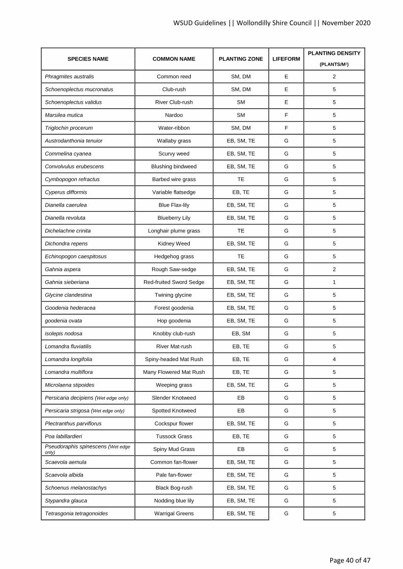
WSUD Guidelines || Wollondilly Shire Council || November 2020
Page 40 of 47
SPECIES NAME COMMON NAME PLANTING ZONE LIFEFORM PLANTING DENSITY
(PLANTS/M²)
Phragmites australis Common reed SM, DM E 2
Schoenoplectus mucronatus Club-rush SM, DM E 5
Schoenoplectus validus River Club-rush SM E 5
Marsilea mutica Nardoo SM F 5
Triglochin procerum Water-ribbon SM, DM F 5
Austrodanthonia tenuior Wallaby grass EB, SM, TE G 5
Commelina cyanea Scurvy weed EB, SM, TE G 5
Convolvulus erubescens Blushing bindweed EB, SM, TE G 5
Cymbopogon refractus Barbed wire grass TE G 5
Cyperus difformis Variable flatsedge EB, TE G 5
Dianella caerulea Blue Flax-lily EB, SM, TE G 5
Dianella revoluta Blueberry Lily EB, SM, TE G 5
Dichelachne crinita Longhair plume grass TE G 5
Dichondra repens Kidney Weed EB, SM, TE G 5
Echinopogon caespitosus Hedgehog grass TE G 5
Gahnia aspera Rough Saw-sedge EB, SM, TE G 2
Gahnia sieberiana Red-fruited Sword Sedge EB, SM, TE G 1
Glycine clandestina Twining glycine EB, SM, TE G 5
Goodenia hederacea Forest goodenia EB, SM, TE G 5
goodenia ovata Hop goodenia EB, SM, TE G 5
isolepis nodosa Knobby club-rush EB, SM G 5
Lomandra fluviatilis River Mat-rush EB, TE G 5
Lomandra longifolia Spiny-headed Mat Rush EB, TE G 4
Lomandra multiflora Many Flowered Mat Rush EB, TE G 5
Microlaena stipoides Weeping grass EB, SM, TE G 5
Persicaria decipiens (Wet edge only) Slender Knotweed EB G 5
Persicaria strigosa (Wet edge only) Spotted Knotweed EB G 5
Plectranthus parviflorus Cockspur flower EB, SM, TE G 5
Poa labillardieri Tussock Grass EB, TE G 5
Pseudoraphis spinescens (Wet edge
only) Spiny Mud Grass EB G 5
Scaevola aemula Common fan-flower EB, SM, TE G 5
Scaevola albida Pale fan-flower EB, SM, TE G 5
Schoenus melanostachys Black Bog-rush EB, SM, TE G 5
Stypandra glauca Nodding blue lily EB, SM, TE G 5
Tetrasgonia tetragonoides Warrigal Greens EB, SM, TE G 5

WSUD Guidelines || Wollondilly Shire Council || November 2020
Page 41 of 47
SPECIES NAME COMMON NAME PLANTING ZONE LIFEFORM PLANTING DENSITY
(PLANTS/M²)
Themeda triandra Kangaroo Grass EB, SM, TE G 5
Viola hederacea Ivy-leaved Violet EB, SM, TE G 5
Hydrilla verticillata Water thyme SU S 5
Myriophyllum varifolium Common Water-milfoil SU S 5
Myriophyllum variifolium Water Milfoil DM, SU S 5
Ottelia ovalifolia Swamp Lily SU S 5
Vallisneria gigantea Ribbonweed SU S 5
Baeckea linifolia Weeping baeckea EB, SM, TE SH 1
Banksia robour Swamp banksia EB, SM, TE SH 0.5
Bauera rubioides River Rose EB, SM, TE SH 2
Breynia oblongifolia Coffee bush TE SH 2
Callistemon citrinus Red Bottlebrush EB, SM, TE SH 1
Callistemon linearis Narrow-leaved bottlebrush EB, SM, TE SH 1
Callistemon rigidus Stiff bottlebrush EB, SM, TE SH 1
Hakea salicifolia Willow-leaved hakea EB, SM, TE SH 0.5
Hymenanthera dentata Tree violet EB, SM, TE SH 1
Leptospermum polygalifolium Tantoon EB, SM, TE SH 0.5
lomatia myricoides River lomatia EB, SM, TE SH 1
Melaleca squamea Swamp honey-myrtle EB, SM, TE SH 0.5
Melaleuca erubescens Rosy Honey-myrtle EB, SM, TE SH 1
Melaleuca hypericifolia Hillock bush EB, SM, TE SH 0.5
Melaleuca thymifolia Thyme honey-myrtle EB, SM, TE SH 2
Myoporum acuminatum Boobialla TE SH 1
Notelaea longifolia Large Mock-olive TE SH 1
Ozothamnus diosmifolius Rice flower TE SH 1
Philotheca myoporoides Long-leaf Wax Flower EB, SM, TE SH 1
Pittosporum revolutum Wild Yellow Jasmine TE SH 1
Solanum prinophyllum Forest nightshade TE SH 4
Trema tomentosa Native Peach TE SH 0.5
Viminaria juncea Native broom EB, SM, TE SH 0.5
Westringia longifolia Long-leaved Westringia EB, SM, TE SH 1
Acacia floribunda White sally wattle TE T 0.1
Acmena smithii Lilly pilly TE T 0.1
Allocasuarina littoralis Black she-oak TE T 0.25
Allocasuarina torulosa Forest Oak TE T 0.1

WSUD Guidelines || Wollondilly Shire Council || November 2020
Page 42 of 47
SPECIES NAME COMMON NAME PLANTING ZONE LIFEFORM PLANTING DENSITY
(PLANTS/M²)
Alphitonia excelsa Red ash TE T 0.1
Angophora subvelutina Broad-leaved apple TE T 0.1
Backhousia myrtifolia Grey myrtle TE T 0.1
Brachychiton populneus Kurragong TE T 0.1
Callistemon salignus Willow bottlebrush EB, SM, TE T 0.1
Elaeocarpus reticulatus Blueberry ash TE T 0.1
Glochidion ferdinandi Cheese tree TE T 0.1
Hymenosporum flavum Native frangipani TE T 0.1
Melaleuca decora White feather honeymyrtle EB, SM, TE T 0.1
Melaleuca linariifolia Snow-in-summer EB, SM, TE T 0.1
Melaleuca nodosa Prickly-leaved paperbark EB, SM, TE T 0.1
Melaleuca styphelioides Prickly-leaved Tea Tree EB, SM, TE T 0.1
Melia azedarach White cedar TE T 0.1
tristaniopsis laurina Water gum EB, SM, TE T 0.1