water supply grid corfe mullen to salisbury transfer mainthe corfe mullen to salisbury transfer main...
TRANSCRIPT

The water supply grid is the largest scheme ever undertaken by Wessex Water. The programme comprises a series of projects designed to resolve resilience issues within the water supply network. The grid will improve interconnectivity within the existing water supply system to enable water to be moved from areas of surplus to
areas of need and hence improve resilience to drought and unforeseen events.
Wessex Water’s supply areaWessex Water provides water to an area of the south west of England, covering approximately 7,500km2 including Dorset, Somerset, Wiltshire and parts of Gloucestershire and Hampshire.
During an average year, the company produces approximately 350 million litres of potable water each day. The supply network is currently split up into four distinct areas, schematised in Figure 1 below (right):
• South resource zone: (Dorset) supplied by groundwater sources.
• Eastresourcezone: (Salisbury and East Wiltshire) supplied from a number of local groundwater sources and not connected to the wider supply system.
• Northresourcezone: (Bath, North and West Wiltshire, East Somerset) supplied from various groundwater sources around Malmesbury and Wiltshire, and from a surface water source near Yeovil.
• West resources zone: (Bridgwater, Taunton and West Somerset) supplied from the major surface water and reservoir sources in Somerset at Maundown, Ashford and Durleigh, linked by a spine main system.
Water Treatment & Supply www.WaterProjectsOnline.com
Page 298 UK Water Projects 2013
Illustration of the construction of a typical water supply pipeline - Courtesy of Wessex Water
Why is the scheme needed?The water supply grid is required to enable Wessex Water to meet the following legal and regulatory obligations:
• The legal obligations in the National Environment Programme issued by the Environment Agency, specifically associated with reductions in the amount of water that Wessex Water can extract from certain underground water sources from 2018 onwards, as required under the EU Habitats Directive.
Figure 1 – Wessex Water’s current supply network and zonesCourtesy of Wessex Water
Water Supply GridCorfe Mullen to Salisbury Transfer Mainby Drummond Modley FICE FCIWEM, Davin Eversett HND, Martin Wood BSc & Eliot Simons BA (Hons) MCIWEM
LEGEND
Existing network
www.WaterProjectsOnline.com Water Treatment & Supply
UK Water Projects 2013 Page 299
• The legally binding undertaking agreed with the Drinking Water Inspectorate, to ensure compliance with Water Supply (Water Quality) Regulations 2000, associated with high levels of nitrates in certain untreated water sources largely from agricultural fertiliser.
• The regulatory outputs set by Ofwat, associated with the security of water supply to their customers served by a single source of water only.
• The statutory duty to balance the supply of and demand for water up to the year 2035 as set out in the Water Resources Management Plan approved by Defra in 2010.
The water supply grid will therefore allow Wessex Water to meet future demand for water and:
• Improve the security of supply for customers – even in the event of a catastrophic failure.
• Meet reductions in abstraction licenses required by the Environment Agency to improve flows in some rivers and protect their ecology.
• Deal with seasonal or occasional deteriorating raw water quality – particularly increasing concentrations of nitrates at some groundwater sources.
The Corfe Mullen to Salisbury transfer mainThe Corfe Mullen to Salisbury transfer scheme is a key component within the Water Supply Grid project. It will provide a new pipeline system that will link together the southern and central areas of the company’s supply network and enable the improved transfer of water between these different areas to help meet these obligations.
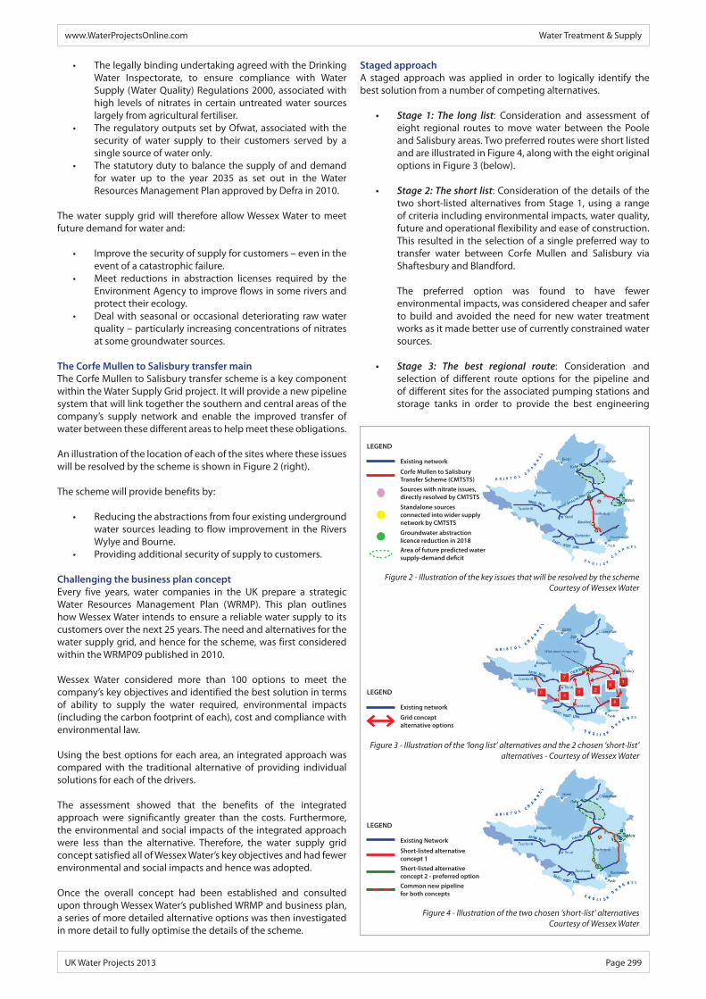
An illustration of the location of each of the sites where these issues will be resolved by the scheme is shown in Figure 2 (right).
The scheme will provide benefits by:
• Reducing the abstractions from four existing underground water sources leading to flow improvement in the Rivers Wylye and Bourne.
• Providing additional security of supply to customers.
Challenging the business plan conceptEvery five years, water companies in the UK prepare a strategic Water Resources Management Plan (WRMP). This plan outlines how Wessex Water intends to ensure a reliable water supply to its customers over the next 25 years. The need and alternatives for the water supply grid, and hence for the scheme, was first considered within the WRMP09 published in 2010.
Wessex Water considered more than 100 options to meet the company’s key objectives and identified the best solution in terms of ability to supply the water required, environmental impacts (including the carbon footprint of each), cost and compliance with environmental law.
Using the best options for each area, an integrated approach was compared with the traditional alternative of providing individual solutions for each of the drivers.
The assessment showed that the benefits of the integrated approach were significantly greater than the costs. Furthermore, the environmental and social impacts of the integrated approach were less than the alternative. Therefore, the water supply grid concept satisfied all of Wessex Water’s key objectives and had fewer environmental and social impacts and hence was adopted.
Once the overall concept had been established and consulted upon through Wessex Water’s published WRMP and business plan, a series of more detailed alternative options was then investigated in more detail to fully optimise the details of the scheme.
Staged approachA staged approach was applied in order to logically identify the best solution from a number of competing alternatives.
• Stage 1: The long list: Consideration and assessment of eight regional routes to move water between the Poole and Salisbury areas. Two preferred routes were short listed and are illustrated in Figure 4, along with the eight original options in Figure 3 (below).
• Stage2:Theshortlist: Consideration of the details of the two short-listed alternatives from Stage 1, using a range of criteria including environmental impacts, water quality, future and operational flexibility and ease of construction. This resulted in the selection of a single preferred way to transfer water between Corfe Mullen and Salisbury via Shaftesbury and Blandford.
The preferred option was found to have fewer environmental impacts, was considered cheaper and safer to build and avoided the need for new water treatment works as it made better use of currently constrained water sources.
• Stage 3: The best regional route: Consideration and selection of different route options for the pipeline and of different sites for the associated pumping stations and storage tanks in order to provide the best engineering
Figure 2 - Illustration of the key issues that will be resolved by the schemeCourtesy of Wessex Water
Figure 3 - Illustration of the ‘long list’ alternatives and the 2 chosen ‘short-list’ alternatives - Courtesy of Wessex Water
Figure 4 - Illustration of the two chosen ‘short-list’ alternativesCourtesy of Wessex Water
LEGEND
Existing network
Grid conceptalternative options
LEGEND
Existing network
Corfe Mullen to Salisbury Transfer Scheme (CMTSTS)Sources with nitrate issues, directly resolved by CMTSTS
Standalone sourcesconnected into wider supply network by CMTSTS
Groundwater abstraction licence reduction in 2018Area of future predicted water supply-demand deficit
LEGEND
Existing Network
Short-listed alternative concept 1Short-listed alternativeconcept 2 - preferred optionCommon new pipelinefor both concepts

Water Treatment & Supply www.WaterProjectsOnline.com
Page 300 UK Water Projects 2013
solution whilst avoiding, where possible, areas of environmental sensitivity.
• Stage 4: The best overall route: Consideration and assessment of options to accommodate known local ‘pinch-points’ in the preferred regional route identified from Stage 3.
Description of the transfer schemeA schematic of the Corfe Mullen to Salisbury transfer scheme is shown in Figure 5 (below). The transfer scheme itself has been carefully routed to maximise the use of existing Wessex Water assets. As a result there is only a requirement for three additional sites along the 64km route with all the rest of the required above ground assets being located either within existing site boundaries or as extensions to them.
Sturminster Marshall to Summerslade DownThe Scheme will use an existing pipeline to transfer water between Corfe Mullen Water Treatment Works (WTW) and Sturminster Marshall WTW.
The water supply pipeline between Sturminster Marshall and Summerslade Down is approximately 44km long, with connections to the existing Wessex Water storage tanks at Snowsdown and Littledown along the route. The bidirectional pipeline varies in size between twin 350mm and single 600mm diameter and will transfer up to 22ML/d from the southern water resource zone.
In addition to the new pipeline, a number of new pumping stations and service reservoirs are required along the route to ensure the effective operation of the water supply system. The storage tanks are required to provide a separate buffer volume for the transfer that can be operated independently from the local distribution storage tanks to ensure the transfer does not impact on the direct
supply to local customers. The locations of these sites are primarily determined by the need to locate them adjacent to existing Wessex Water sites along the route of the proposed pipelines, but also take account of engineering requirements, topography and environmental sensitivity. The main sites along the southern section of the route are:
• CorfeMullen Pumping Station: A new pumping station, located within the existing operational site boundary at Corfe Mullen WTW.
• SturminsterMarshallStorageTankAndPumpingStation: A new 5ML storage tank connected to a new pumping station is required.
• Snowsdown storage tank: A new 3ML storage tank is required at Snowsdown adjacent to the existing Wessex Water storage tank.
• Pimperne Pumping Station: A new pumping station is required to the west of Pimperne to allow water to be pumped from Snowsdown Storage Tank to Littledown Storage Tank.
• Littledown Storage Tank: A new 2ML storage tank is required at Littledown adjacent to the existing Wessex Water storage tank.
• Monkton Deverill Pumping Station: A new pumping station is required at Monkton Deverill to allow water to be pumped between Littledown and the new storage tank at Summerslade Down. It will also be required to transfer water into the existing Wessex Water network fed from the Whitesheets Storage Tanks. The new pumping station will be located adjacent to existing agricultural buildings, south of the village.
• SummersladeDownStorageTank: A new 8ML storage tank is also required at Summerslade Down.
Codford to Camp Hill pipelineThe scheme will use an existing pipeline between Summerslade Down and Codford WTW. This pipeline will become bi-directional but allows flows by gravity to Codford WTW where the next new link commences from.
This section will comprise 19km of new water pipeline between the existing Codford WTW and the existing Wessex Water storage tank at Camp Hill. The bi-directional pipeline will be a single 400mm diameter main and will transfer up to 14ML/d into Salisbury. The pipeline route runs along the Wylye valley running to the south of the River Wylye and the Warminster to Salisbury railway line for the majority of its length. The following works are also required as part of the scheme:
• CodfordWTW: A new pumping station and 2ML storage tank is required at the existing Codford WTW. In addition, improvements are also required to upgrade and extend the existing water treatment works, specifically to enhance the removal of iron.
• Wylye WTW: An additional pump building will be constructed.
• Camp Hill storage tank: A new 5.6ML storage tank is required which will act as a dedicated transfer storage tank and will become the primary feed for Salisbury. The existing storage tank will be dedicated to maintaining supplies direct to customers.
Overall control of transfer schemeIn order to maximise the benefit of the transfer scheme it has been routed to connect up with existing Wessex Water assets and does provide additional resilience to these areas. It does in turn add significantly to the complexity of the control as the transfer can be reversible to provide greater support in the event of a major outage within the Wessex Water region. It will also interface with existing distribution facilities that supply a significant number of customers.
Figure 5 – Schematic of The Corfe Mullen to Salisbury Transfer SchemeCourtesy of Wessex Water

To manage this Wessex Water is in the process of building an Optimiser control system that will manage the transfer of water throughout the Wessex Water system. This is currently in development with Tynemarch Systems Ltd. The Optimiser will be a centrally controlled and managed system that will schedule transfers in the most efficient way whilst still operating within the constraints built into the system to ensure the new transfer links are fully conditioned to minimise any risk of water quality issues.
In addition to this there will be a dedicated control system for the Sturminster Marshall to Summerslade link due to the complex interface with the existing distribution storage tanks. This will ensure a robust back up for the Optimiser.
The control between the sites will utilise two different routes of communication comprising microwave and/or fibre optic with backup from radio link or GSM/BT landline.
Managing environmental impactsAt the end of April 2013, the scheme was granted full planning permission, following the submission of the planning application and full environmental statement to three planning authorities: Wiltshire Council, East Dorset District Council and North Dorset District Council, as the scheme crosses all three administrative areas. The detail design is due to be completed by October 2013.
The environmental impact assessment reviewed potential impacts and concluded that the majority of impacts from the scheme will be temporary during construction and of negligible or minor significance. Best practice site construction techniques will minimise these impacts during construction.
Residual permanent impacts from the scheme are limited to minor adverse impacts on ecology (from washout discharges to watercourses), the historic environment and the landscape.
The permanent impacts on ecology can be managed through controlled use of the pipeline and storage tank washouts. The temporary impacts on ecology can all be managed through suitable construction techniques, habitat reinstatement and enhancement where possible.
The impacts that have been identified on the historic environment will be managed through targeted excavation and cataloguing along with careful routeing of the pipeline within the 50m planning corridor to accommodate unforeseen areas of archaeological significance.
There are major positive benefits from the scheme in terms of a long term improvement in the security of regional water supply and reduced groundwater abstractions for public supply from the more sensitive upper reaches of the river catchment areas for the river Wylye and Bourne, which will help improve in-river ecology.
With measures in place to mitigate the temporary and permanent impacts, any adverse impacts identified as a result of the scheme are outweighed by the more widespread benefits from the provision of a reliable water supply for the future and the reduced abstractions from the upper reaches of the River Avon catchment.
Description of constructionWessex Engineering and Construction Services (WECS) are managing the overall delivery programme, with both WECS and Atkins Ltd providing engineering design, planning and environmental services. This is being undertaken in close partnership with Water Supply Grid contractors: WECS Civils, WECS Mainlaying and Trant Construction Ltd.
To build the pipeline, the width of the area affected will typically be 20-25m along the length of the scheme, but this may increase locally to around 30-35m where the pipeline crosses roads, watercourses,
www.WaterProjectsOnline.com Water Treatment & Supply
UK Water Projects 2013 Page 301
CIVIL ENGINEERING
Mwyndy Cross Industries, Cardiff Road, Pontyclun, Rhondda Cynon Taff,CF72 8PN, Tel: (01443) 449200
[email protected] www.lewis-ltd.co.uk
Lewis Civil Engineering is
committed to the highest possible
standards in civil engineering.
Our aim is to utilise our extensive
experience and professional
approach to the benefit of our
clients whether large or small.

Water Treatment & Supply www.WaterProjectsOnline.com
Page 302 UK Water Projects 2013
Figure 6 - Courtesy of Wessex Water
railways and the like to facilitate safe working. At hedge crossings this will typically be reduced to 5m in order to minimise the length of hedge affected.
Typically minor roads, byways, footpaths and other rights of way will be crossed using open cut construction meaning that the pipeline will be laid in an open, excavated trench as shown in the illustration on page 1. This means that these rights of way will be subject to temporary closure whilst the pipeline is constructed across them. Smaller watercourses and ditches will also be crossed using open cut techniques where practicable and in agreement with the regulatory authorities.
Where more major or very sensitive obstacles are encountered, such as primary roads, railways, major watercourses or ecologically valuable hedgerows it is possible to install pipes without digging a trench, typically using directional drilling or auger boring, where a
For more information please contact
Quantum Engineering Developments LtdQuantum House, Saxon Business Park
Stoke Prior, Bromsgrove B60 4AD
Phone: 01527 577888Email: [email protected]
What can Quantum do for you today?
www.quantumeng.co.uk
Surge suppression packages •Saturator vessels •
Booster pump packages •Ozone packages •
Instrument air packages •
Vessel refurbishment •Qube controls •
Duplex relief valve sets •DAF compressor sets •
Hydroburst packages •
tunnel or passage is cut under the crossing and the pipe inserted into this.
6 (No.) new storage tanks sized between 2ML to 8ML and 4 (No.) new large transfer pumping stations will be built along the line of the 64km transfer main. The west elevation of one of the new storage tanks and pumping stations is shown above in Figure 6.
Construction of the Corfe Mullen to Salisbury transfer scheme will be phased over a 4-year period, commencing in autumn 2013 for completion and commissioning by December 2017.
The Editor & Publishers would like to thank Drummond Modley, Programme Manager, Davin Eversett, Project Manager and Martin Wood, Technical Manager, all with Wessex Water, and Eliot Simons, Project Director with Atkins Limited, for providing the above article for publication.