water & wastewater systems - county of …. ten-state standards recommended standards for sewage...
TRANSCRIPT
S
S
S
S
WATER &
WASTEWATER
SYSTEMS
DETAILED
SPECIFICATIONS
MOORE COUNTY
PUBLIC WORKS
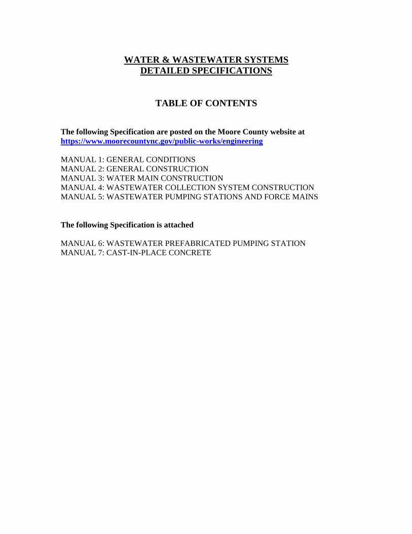
WATER & WASTEWATER SYSTEMS
DETAILED SPECIFICATIONS
TABLE OF CONTENTS
The following Specification are posted on the Moore County website at
https://www.moorecountync.gov/public-works/engineering
MANUAL 1: GENERAL CONDITIONS
MANUAL 2: GENERAL CONSTRUCTION
MANUAL 3: WATER MAIN CONSTRUCTION
MANUAL 4: WASTEWATER COLLECTION SYSTEM CONSTRUCTION
MANUAL 5: WASTEWATER PUMPING STATIONS AND FORCE MAINS
The following Specification is attached
MANUAL 6: WASTEWATER PREFABRICATED PUMPING STATION
MANUAL 7: CAST-IN-PLACE CONCRETE
WASTEWATER
PREFABRICATED
PUMPING STATION
STANDARDS & SPECIFICATIONS MANUAL
MOORE COUNTY PUBLIC WORKS DEPARTMENT

PREFACE
These standards are for design and construction of utilities, which will come under the
jurisdiction of Moore County Public Works (MCPW). These standards alone do not
constitute a complete set of construction documents. The owner’s or developer’s
Professional Engineer is responsible for design and computation of complete construction
and contract documents. These standards are set forth as the minimal requirements to achieve
a suitable quality level for utilities which will become the property of MCPW.
The standards do not include a complete commentary on methods of installation and detailed
information of quality of workmanship in place. The owner’s or developer’s Professional
Engineer must include detailed information on methods of construction and should expand on
the testing and any of the special requirements to the engineer’s satisfaction, subject to the
approval of MCPW.
From time to time, these standards will be amended and/or expanded at the request of the
MCPW Engineering Department and with approval of the Director. It will be the responsibility
of the owner or developer to contact the MCPW to obtain updated standards.
There may be circumstances whereby the design engineer may wish to propose changes or
modifications to these standards, when this occurs permission from the County Engineer shall be
obtained prior to submission to NCDEQ.
DISCLAMER
To the best of their ability, the authors have insured that material presented in this manual is
accurate and reliable. The design of engineered facilities, however, requires considerable
judgment on the part of designer. It is the responsibility of the design professional to insure that
techniques utilized are appropriate for a given situation. Therefore, neither Moore County Public
Works, nor any author or other individual, group, etc., associated with production of this manual,
accepts any responsibility for improper design, any loss, damage, or injury as a result of the use
of this manual.
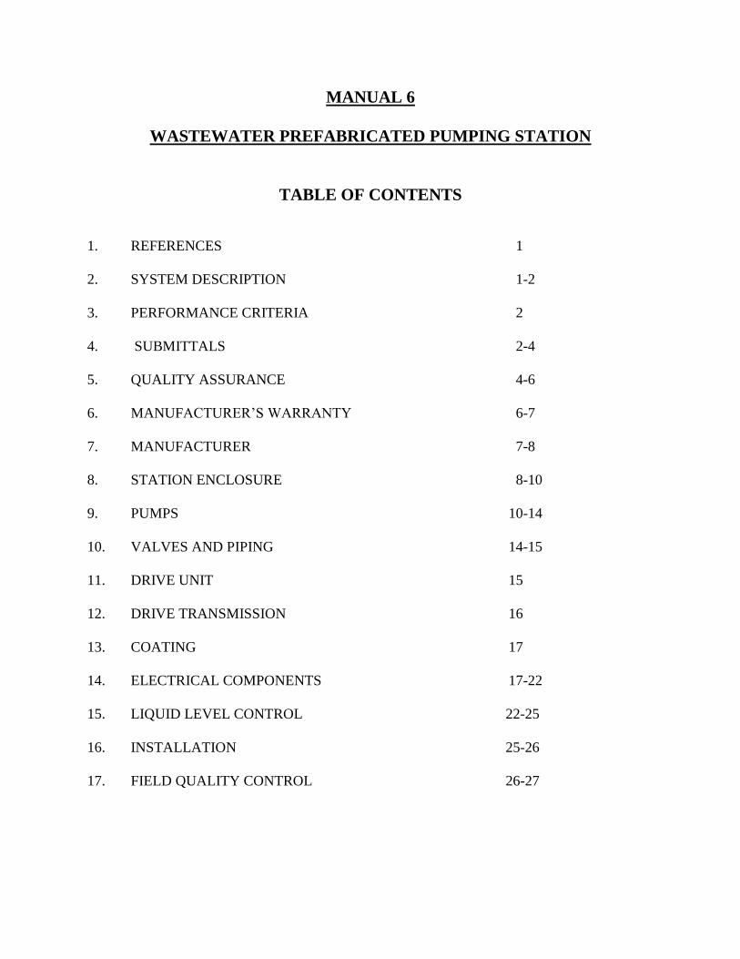
MANUAL 6
WASTEWATER PREFABRICATED PUMPING STATION
TABLE OF CONTENTS
1. REFERENCES 1
2. SYSTEM DESCRIPTION 1-2
3. PERFORMANCE CRITERIA 2
4. SUBMITTALS 2-4
5. QUALITY ASSURANCE 4-6
6. MANUFACTURER’S WARRANTY 6-7
7. MANUFACTURER 7-8
8. STATION ENCLOSURE 8-10
9. PUMPS 10-14
10. VALVES AND PIPING 14-15
11. DRIVE UNIT 15
12. DRIVE TRANSMISSION 16
13. COATING 17
14. ELECTRICAL COMPONENTS 17-22
15. LIQUID LEVEL CONTROL 22-25
16. INSTALLATION 25-26
17. FIELD QUALITY CONTROL 26-27
1 of 27
MANUAL 6 - WASTEWATER PREFABRICATED PUMPING STATION
1. REFERENCES
Publications listed below form part of this specification to extent referenced in the text by
basic designation only. Consult latest edition of publication unless otherwise noted.
1. American National Std. Institute (ANSI) / American Water Works Assoc. (AWWA)
a. ANSI B16.1 Cast iron pipe flanges and flanged fittings.
b. ANSI/AWWA C115/A21.51 Cast/ductile iron pipe with threaded flanges.
c. ANSI 253.1 Safety Color Code for Marking Physical Hazards.
d. ANSI B40.1 Gages, Pressure and Vacuum.
e. AWWA C508 Single Swing Check Valves.
2. American Society for Testing and Materials (ASTM)
a. ASTM A48 Gray Iron Castings.
b. ASTM A126 Valves, Flanges, and Pipe Fittings.
c. ASTM A307 Carbon Steel Bolts and Studs.
d. ASTM A36 Structural Steel.
3. Institute of Electrical and Electronics Engineers (IEEE)
a. ANSI/IEEE Std 100 Standard Dictionary of Electrical Terms.
b. ANSI/IEEE Std 112 Test Procedure for Polyphase Induction
c. IEEE Std 242 Protection of Industrial and Control Power Systems.
4. National Electric Code (NEC) / National Electrical Manufacturers Assoc. (NEMA)
a. NEC National Electric Code.
b. NEC 701 National Electric Code article 701.
c. NEMA Std MG1 Motors and Generators.
5. Miscellaneous References
a. Ten-State Standards Recommended Standards for Sewage Works.
b. Hydraulic Institute Std for Centrifugal, Rotary and Reciprocating Pumps.
c. NMTBA and JIC Std National Machine Tool Builders Association and Joint
Industrial Council Standards
d. ISO 9001 International Organization for Standardization.
2. SYSTEM DESCRIPTION
A. Contractor shall furnish and install one factory built above ground, automatic pump
station. The station shall be complete with all equipment specified herein; factory
assembled in a fiberglass reinforced polyester resin enclosure.
2 of 27
B. In addition to the station enclosure, principle items of equipment shall include two
horizontal, self-priming, centrifugal sewage pumps, V-belt drives, motors, internal
piping, valves, motor control panel, automatic liquid level control system, and
internal wiring.
C. Factory built pump station design, including materials of construction, pump features,
valves and piping, and motor controls shall be in accordance with requirements listed
under PART 2 - PRODUCTS of this section.
3. PERFORMANCE CRITERIA
A. Pumps must be designed to handle raw, unscreened, domestic sanitary sewage.
Pumps shall have 4" suction connection, and 3" discharge connection. Each pump
shall be selected to perform under following operating conditions:
1. Capacity (GPM) 250
2. Total Dynamic Head (FT) 152
3. Total Dynamic Suction Lift(FT) 10
4. Maximum Repriming Lift (FT) 10
5. Maximum Static Suction Lift(FT) 10
B. Site power furnished to pump station shall be 3 phase, 60 hertz, 480 volts and 4 wire
maintained within industry standards. The available fault current provided at the
pump station control panel is 10 kA rms symmetrical. Voltage tolerance shall be plus
or minus 10 percent. Phase-to-phase unbalance shall not exceed 1% average voltage
as set forth in NEMA Standard MG-1. Control voltage shall not exceed 132 volts.
4. SUBMITTALS
A. PRODUCT DATA
1. Prior to fabrication, pump station manufacturer shall submit an electronic copy
of submittal data for review and approval.
2. Submittal shall include shop drawings, electrical ladder logic drawings, and
support data as follows: Catalog cut sheets reflecting characteristics for major
items of equipment, materials of construction, major dimensions, motor and v-
belt drive data, pump characteristic curves showing the design duty point
capacity (GPM), head (FT), net positive suction head required (NPSHr), and
hydraulic brake horsepower (BHP). Electrical components used in the motor
branch and liquid level control shall be fully described.
3. Shop drawings shall provide layout of mechanical equipment and anchor bolt
locations for station. Pipe penetrations and station access clearances shall be
dimensioned relative to the station centerline. The electrical ladder logic
3 of 27
drawings shall illustrate motor branch and liquid level control circuits to extent
necessary to validate function and integration of circuits to form a complete
working system.
B. OPERATIONS AND MAINTENANCE MANUALS
1. Operation shall be in accordance with written instructions provided by the pump
station manufacturer. Comprehensive instructions supplied at time of shipment
shall enable personnel to properly operate and maintain all equipment supplied.
Content and instructions shall assume operating personnel are familiar with
pumps, motors, piping and valves, but lack experience on exact equipment
supplied.
2. Documentation shall be specific to the pump station supplied and collated in
functional sections. Each section shall combine to form a complete system
manual covering all aspects of equipment supplied by the station manufacturer.
Support data for any equipment supplied by others, even if mounted or included
in overall station design, shall be provided by those supplying the equipment.
Instructions shall include the following as a minimum:
a. Functional description of each major component, complete with operating
instructions.
b. Instructions for operating pumps and pump controls in all modes of
operation.
c. Calibration and adjustment of equipment for initial start-up, replacement of
level control components, or as required for routine maintenance.
d. Support data for commercially available components not produced by the
station manufacturer, but supplied in accordance with the specifications,
shall be supported by literature from the prime manufacturer and
incorporated as appendices.
e. Electrical schematic diagram of the pump station circuits shall be in
accordance with NFPA 79. Schematics shall illustrate, to the extent of
authorized repair, pump motor branch, control and alarm system circuits
including interconnections. Wire numbers and legend symbols shall be
shown. Schematic diagrams for individual components, not normally
repairable by the station operator, need not be included. Details for such
parts shall not be substituted for an overall system schematic. Partial
schematics block diagrams, and simplified schematics shall not be provided
in lieu of an overall system diagram.

4 of 27
f. Mechanical layout drawing of the pump station and components, prepared in
accordance with good commercial practice, shall provide installation
dimensions and location of all pumps, motors, valves and piping.
3. Operation and maintenance instructions which rely on vendor cut-sheets and
literature which include general configurations, or require operating personnel to
selectively read portions of the manual shall not be acceptable. Operation and
maintenance instructions must be specific to equipment supplied in accordance
with these specifications.
5. QUALITY ASSURANCE
A. The pumps and pump station manufacturer must be ISO 9001:2000 revision
certified, with scope of registration including design control and service after sales
activities.
B. Upon request from the engineer, the pump station manufacturer shall prove financial
stability and ability to produce the station within the specified delivery schedules.
Evidence of facilities, equipment and expertise shall demonstrate the manufacturer's
commitment to long term customer service and product support.
C. In order to unify responsibility for proper operation, it is the intent of these
Specifications that all system components be furnished by a single supplier (unitary
source) and that source shall be the pump manufacturer. The pumps must be of
standard catalog design, totally warranted by the manufacturer. Under no
circumstances will a system consisting of parts compiled and assembled by a
manufacturer’s representative or distributor be accepted.
D. Manufacturer must show proof of original product design and testing. Products
violating intellectual property regulations shall not be allowed, as they may violate
international law and expose the user or engineer to unintended liabilities. “Reverse-
engineered” products fabricated to substantially duplicate the design of original
product shall not be allowed, as they may contain substantial differences in
tolerances and material applications addressed in the original design, which may
contribute to product failure.
E. The term “pump manufacturer” or “pump station manufacturer” shall be defined as
the entity which designs, machines, assembles, hydraulically tests and warranties the
final product. Any entity that does not meet this definition will not be considered a
“pump manufacturer” or “pump station manufacturer” and is not an acceptable
supplier. For quality control reasons and future pump and parts availability, all
major castings of the pump shall be sourced and machined in North America.
5 of 27
F. PUMP PERFORMANCE CERTIFICATIONS
1. All internal passages, impeller vanes, and recirculation ports shall pass a 3"
spherical solid. Smaller internal passages that create a maintenance nuisance or
interfere with priming and pump performance shall not be permitted. Upon
request from the engineer, manufacturer’s certified drawings showing size and
location of the recirculation port(s) shall be submitted for approval.
2. Reprime Performance
a. Consideration shall be given to the sanitary sewage service anticipated, in
which debris is expected to lodge between the suction check valve and its seat,
resulting in the loss of the pump suction leg, and siphoning of liquid from the
pump casing to the approximate center line of the impeller. Such occurrence
shall be considered normal, and the pump must be capable of automatic,
unattended operation with an air release line installed.
b. During unattended operation, the pump shall retain adequate liquid in the
casing to insure automatic repriming while operating at its rated speed in a
completely open system. The need for a suction check valve or external
priming device shall not be required.
c. Pump must be capable of repriming 25 vertical feet at the specified speed and
impeller diameter. Reprime lift is defined as the static height of the pump
suction above the liquid, while operating with only one-half of the liquid
remaining in the pump casing. The pump must reprime and deliver full
capacity within five minutes after the pump is energized in the reprime
condition. Reprime performance must be confirmed with the following test
set-up:
1) A check valve to be installed down stream from the pump discharge
flange. The check valve size shall be equal (or greater than) the pump
discharge diameter.
2) A length of air release pipe shall be installed between pump and the
discharge check valve. This line shall be open to atmosphere at all times
duplicating the air displacement rate anticipated at a typical pump station
fitted with an air release valve.
3) The pump suction check valve shall be removed. No restrictions in the
pump or suction piping will prevent the siphon drop of the suction leg.
Suction pipe configuration for reprime test shall incorporate a 2 feet
minimum horizontal run, a 90o elbow and vertical run at the specified lift.
Pipe size shall be equal to the pump suction diameter.

6 of 27
4) Impeller clearances shall be set as recommended in the pump service
manual.
5) Repeatability of performance shall be demonstrated by testing five
consecutive reprime cycles. Full pump capacity (flow) shall be achieved
within five minutes during each cycle.
6) Liquid to be used for reprime test shall be water.
3. Upon request from the engineer, certified reprime performance test results,
prepared by the manufacturer, and certified by a registered professional engineer,
shall be submitted for approval prior to shipment.
G. FACTORY SYSTEM TEST
1. All internal components including the pumps, motors, valves, piping and controls
will be tested as a complete working system at the manufacturer's facility. Tests
shall be conducted in accordance with Hydraulic Institute Standards at the
specified head, capacity, rated speed and horsepower. Factory operational test
shall simulate actual performance anticipated for the complete station.
2. Upon request from the engineer, the operational test may be witnessed by the
engineer, and/or representatives of his choice, at the manufacturer's facility.
H. The manufacturer’s technical representative shall inspect the completed installation,
correct or supervise the correction of any defect or malfunction, and instruct
operating personnel in the proper operation and maintenance of the equipment as
described in Part 3 of this section.
6. MANUFACTURER'S WARRANTY
A. The pump station manufacturer shall warrant all equipment to be of quality
construction, free of defects in material and workmanship. A written warranty shall
include specific details described below.
1. In addition to defects in material and workmanship, fiberglass reinforced
polyester station enclosures are warranted for sixty (60) months to be resistant to
rust, corrosion, corrosive soils, effects of airborne contamination or physical
failures occurring in normal service for the period of the pump station warranty.
2. All other equipment, apparatus, and parts furnished shall be warranted for sixty
(60) months, excepting only those items that are normally consumed in service,
such as light bulbs, oils, grease, packing, gaskets, O-rings, etc. The pump station
manufacturer shall be solely responsible for warranty of the station and all
components.

7 of 27
B. Components failing to perform as specified by the engineer, or as represented by the
manufacturer, or as proven defective in service during the warranty period, shall be
replaced, repaired, or satisfactorily modified by the manufacturer.
C. It is not intended that the station manufacturer assume liability for consequential
damages or contingent liabilities arising from failure of any vendor supplied product
or part which fails to properly operate, however caused. Consequential damages
resulting from defects in design or delays in delivery are also beyond the
manufacturer's scope of liability.
D. Equipment supplied by others and incorporated into a pump station or enclosure is
not covered by this limited warranty. Any warranty applicable to equipment selected
or supplied by others will be limited solely to the warranty, if any, provided by the
manufacturer of the equipment.
E. This limited warranty shall be valid only when installation is made and use and
maintenance is performed in accordance with manufacturer recommendations. A
start-up report competed by an authorized manufacturer’s representative must be
received by manufacturer within thirty (30) days of the initial date the unit is placed
into service. The warranty shall become effective on the date of acceptance by the
purchaser or the purchaser's authorized agent, or sixty (60) days after installation, or
ninety (90) days after shipment from the factory, whichever occurs first.
7. MANUFACTURER
A. In order to unify responsibility for proper operation of the complete pumping station,
it is the intent of these Specifications that all system components are furnished by a
single supplier (unitary source). The pumping station must be of standard catalog
design, totally warranted by the manufacturer. Under no circumstances will a system
consisting of parts compiled and assembled by a manufacturer's representative or
distributor be accepted. The pump station system integrator must be ISO 9001:2000
revisions certified, with scope of registration including design control and service
after sales activities.
B. The specifications and project drawings depict equipment and materials manufactured
by The Gorman-Rupp Company which are deemed most suitable for the service
anticipated. It is not intended, however, to eliminate other products of equal quality
and performance. The contractor shall prepare his bid based on the specified
equipment for purposes of determining low bid. Award of a contract shall constitute
an obligation to furnish the specified equipment and materials.
C. After execution of the contract, the contractor may offer substitutions to the specified
equipment for consideration. The equipment proposed for substitution must be
superior in construction and performance to that specified in the contract, and the
higher quality must be demonstrated by a list of current users of the proposed
equipment in similar installations.

8 of 27
D. In event the contractor obtains engineer's approval for equipment substitution, the
contractor shall, at his own expense, make all resulting changes to the enclosures,
buildings, piping or electrical systems as required to accommodate the proposed
equipment. Revised detail drawings illustrating the substituted equipment shall be
submitted to the engineer prior to acceptance.
E. It will be assumed that if the cost to the contractor is less for the proposed
substitution, then the contract price shall be reduced by an amount equal to the
savings.
8. STATION ENCLOSURE
A. The station enclosure shall provide sufficient inside area for maintenance personnel to
perform normal operation and maintenance inside, sheltered, and free from foul
weather. The enclosure shall consist of a base to support the pumps and a cover.
Minimum dimensions of the enclosure shall be eight feet by twelve feet and nine feet
in height.
B. The station enclosure shall be manufactured of molded fiberglass reinforced
orthophthalic polyester resins with a minimum of 30% fiberglass, and a maximum of
70% resin. Glass fibers shall have a minimum average length of 1¼ inches. Resin
fillers or extenders shall not be used. Major design considerations shall be given to
structural stability, corrosion resistance, and water-tight properties. The polyester
laminates shall provide a balance of mechanical, chemical, and electrical properties to
insure long maintenance free life. They must be impervious to micro-organisms,
mildew, mold, fungus, corrosive liquids, and gases which can reasonably be expected
to be present in the environment surrounding the wet well. Wood core type
enclosures shall not be considered acceptable and shall be basis for equipment
rejection. See manufacturer's requirements for enclosure warranty in these
specifications.
C. All interior surfaces of the housing shall be gel coated with a polyester resin. It shall
be of suitable thickness and formulated to provide:
1. Maintenance-free service
2. Abrasion resistance
3. Protection from sewage, greases, oils, gasoline, and other common chemicals.
4. Color fastness
5. Gloss retention
D. Interior surfaces of the enclosure cover shall be white for maximum light reflectivity.
The base shall be of a darker color to de-emphasize the presence of dirt, grease, etc.
Colors used for both portions shall result in a pleasing looking structure.
E. The pump station shall be furnished with 1" thick foam insulation which shall be

9 of 27
applied to the walls, door, and roof to achieve an R-6 insulation factor. A gasketed
seal around the door shall also be included.
F. The outside of the enclosure shall be coated with a suitable pigmented resin
compound to insure long, maintenance-free life. The fiberglass enclosure shall be a
regular product of the pump station manufacturer.
G. Station base shall be constructed of pre-cast, reinforced concrete encapsulated in a
fiberglass mold. The design shall resist deformation of the structure during shipping,
lifting, or handling. Base shall incorporate drainage provisions, and an opening sized
to permit installation of piping and service connections to the wet well. After
installation, the opening shall serve as a grout dam to be utilized by the contractor.
The base shall incorporate anchor bolt recesses for securing the complete station to a
concrete pad (supplied by the contractor) in accordance with the project plans.
H. Holes through the base shall be provided for suction and discharge lines, air release
lines, and level control line. Holes for the suction and discharge lines shall be
provided with a grout dam incorporated in a grout retention cavity which the
contractor shall fill at installation with suitable grout to seal each pipe-to-base joint
against the entrance of hazardous gases from the wet well.
I. Station base shall incorporate a suitable flange designed for securing the pump station
to the concrete pad in accordance with the station plans.
J. The enclosure cover shall be provided with a hinged fiberglass reinforced access
door. Minimum dimensions of the door shall be 36 inches wide by 78 inches high for
access by maintenance personnel to station interior. Door shall be a minimum 1 7/8
inch thick and shall be hinged with a minimum of two heavy duty stainless steel
hinges to the enclosure cover. Door shall be furnished with a padlockable handle
connected to a latching mechanism. Latch shall engage door casing or maximum
security against vandalism. All mounting hardware for door casing and door must be
concealed or of such type as to prevent vandalism with ordinary tools.
K. Removable panels shall be supplied on two sides of the enclosure for additional
access to equipment. Location and size shall permit access for routine maintenance
functions such as pump and motor inspection, drive belt adjustment, and pump
clean-out. Non-hinged panels shall be secured with stainless steel tamper-proof
hardware
L. A duplex ground fault indicating utility receptacle providing 115 volts, single phase,
60 hertz shall be mounted inside the pump station. Receptacle shall be NEMA 5-15r
configuration, heavy duty, specification grade and fitted with a weatherproof cover.
The receptacle shall be protected by normal duty circuit breaker.
M. A shuttered exhaust fan with a minimum capacity of 500 CFM to change the air in the
enclosure once every minute, shall be mounted in the end wall approximately

10 of 27
opposite the hinged door opening. An air intake vent shall be mounted in the hinged
door assembly. Both intake and exhaust opening shall be equipped with a screen and
cowl suitably designed to prevent the entrance of rain, snow, rocks, and other foreign
material. The thermostatically controlled exhaust fan shall energize automatically at
approximately 70 degrees F, and turned off at 55 degrees F. Fan circuit shall be
protected by a normal duty circuit breaker.
N. Two enclosed and gasketed 80 watt fluorescent light fixtures shall be provided. The
fixtures shall be NEMA 4, suitable for wet location. The fixtures shall be located to
provide adequate light to all parts of the station and shall not constitute a physical
hazard to inspection or service personnel. Light circuit shall be protected by a normal
duty circuit breaker and shall be provided with a disconnect switch.
O. A 4 KW three-phase wall mounted forced air heater shall be provided for protection
of the pump station equipment. The heater shall maintain an inside/outside
temperature differential of 60 degrees F while operating on the primary electrical
power available to the station. The heater shall be controlled by a thermostat and
contactor and protected by a heavy duty circuit breaker.
9. PUMPS
A. Pump shall be horizontal, self-priming centrifugal type, designed specifically for
handling raw unscreened domestic sanitary sewage or industrial waste. Pump solids
handling capability and performance criteria shall be in accordance with requirements
listed under PART 1 - GENERAL of this section. The manufacturer of the pumps
must be ISO 9001:2000 revision certified, with scope of registration including design
control and service after sales activities.
B. Pump shall be vertically staged incorporating a lower and upper volute casing united
by a ductile iron transition chamber, allowing for a direct and smooth flow path to the
impeller in the upper casing.
C. Pump suction and discharge connections of the lower casing shall be vertically inline
with one another.
D. The cover plates and rotating assemblies shall be interchangeable between both
casings.
E. The discharge port of the upper casing shall be capable of being rotated to allow for
multiple pipe connection orientations.
F. MATERIALS AND CONSTRUCTION FEATURES
1. Pump casings shall be cast iron Class 30 with integral volute scroll. Casing shall
incorporate following features:

11 of 27
a. Mounting feet sized to prevent tipping or binding when pump is completely
disassembled for maintenance.
b. Fill port cover plate, 3 1/2" diameter, shall be opened after loosening a positive
lock clamp bar assembly. In consideration for safety, capscrew threads must
provide slow release of pressure, and the clamp bar shall be retained by detente
lugs. A non-metallic gasket shall prevent adhesion of the fill port cover to the
casing while assuring a reliable seal.
c. Lower casing drain plug shall be at least 1 1/4" NPT to insure complete and
rapid draining.
d. Liquid volume and recirculation port design shall be consistent with
performance criteria listed under PART 1 - GENERAL of this section.
2. Cover plates shall be cast iron Class 30. Design must incorporate the following
maintenance features:
a. Retained by hand nuts for complete access to pump interior. Cover plate
removal must provide ample clearance for removal of stoppages, and allow
service to the impeller, seal, wear plate or check valve without removing
suction or discharge piping.
b. Replaceable wear plate secured to the cover plate by weld studs and nuts shall
be AISI 1015 HRS. Wear plates shall be self-cleaning design ensuring that
debris is cleared away and does not collect on the impeller vanes.
c. In consideration for safety, a pressure relief valve shall be supplied in each
cover plate. Relief valve shall open at 75-200 PSI.
d. Two O-rings of Buna-N material shall seal each cover plate to pump casings.
e. Pusher bolt capability to assist in removal of cover plates. Pusher bolt threaded
holes shall be sized to accept same retaining capscrew as used in rotating
assemblies.
f. An easy-grip handle shall be mounted to the face of each cover plate.
3. Each rotating assembly, which includes impeller, shaft, mechanical shaft seal, lip
seals, bearings, seal plate and bearing housing, must be removable as a single unit
without disturbing the pump casing or piping. Design shall incorporate the
following features:
a. Seal plates and bearing housings shall be cast iron Class 30. Anti-rotation ribs
shall be cast into the seal plates to reduce internal wear and maximize
component life. Separate oil filled cavities, vented to atmosphere and shall be
12 of 27
provided for shaft seal and bearings. Cavities must be cooled by the liquid
pumped. Three lip seals will prevent leakage of oil.
1) Each bearing cavity shall have an oil level sight gauge and fill plug check
valve. The clear sight gauge shall provide easy monitoring of the bearing
cavity oil level and condition of oil without removal of the fill plug check
valve. The check valve shall vent the cavity but prevent introduction of
moist air to the bearings.
2) Each seal cavity shall have an oil level sight gauge and fill/vent plug. The
clear sight gauge shall provide easy monitoring of the seal cavity oil level
and condition of oil without removal of the fill/vent plug.
3) Double lip seals shall provide an atmospheric path providing positive
protection of bearings, with capability for external drainage monitoring.
b. Impellers shall be ductile iron, two vane, semi-open, non-clog, with integral
pump out vanes on the back shroud. Impellers shall be statically or
dynamically balanced. Impeller shall thread onto the pump shaft and be
secured with a lockscrew and conical washer.
c. Shafts shall be AISI 4140 alloy steel unless otherwise specified by the
engineer, in which case AISI 17-4 pH stainless steel shall be supplied.
d. Bearings shall be anti-friction ball type of proper size and design to withstand
all radial and thrust loads expected during normal operation. Bearings shall be
oil lubricated from a dedicated reservoir. Pump designs which use the same oil
to lubricate the bearings and shaft seal shall not be acceptable.
e. Each shaft seal shall be oil lubricated mechanical type. The stationary and
rotating seal faces shall be silicon carbide alloy. Each mating surface shall be
lapped to within three light bands flatness (35 millionths of an inch), as
measured by an optical flat under monochromatic light. The stationary seal seat
shall be double floating by virtue of a dual O-ring design. An external O-ring
secures the stationary seat to the seal plate, and an internal O-ring holds the
faces in alignment during periods of mechanical or hydraulic shock (loads
which cause shaft deflection, vibration, and axial/radial movement).
Elastomers shall be viton; cage and spring to be stainless steel. Seal shall be oil
lubricated from a dedicated reservoir. The same oil shall not lubricate both
shaft seal and shaft bearings. Seals shall be warranted in accordance with
requirements listed under PART 1 - GENERAL of this section.
f. Pusher bolt capability to assist in removal of rotating assemblies. Pusher bolt
threaded holes shall be sized to accept same capscrews as used for retaining
rotating assemblies.
13 of 27
4. Adjustment of the impeller face clearances (distance between impeller and wear
plate) shall be accomplished by external means.
a. Clearances shall be maintained by a four point external shimless cover plate
adjustment system, utilizing a four collar and four adjusting screw design
allowing for incremental adjustment of clearances by hand as required. Each of
the four points shall be lockable to prevent inadvertent clearance increases or
decreases due to equipment vibration or accidental operator contact. The four-
point system also allows for equal clearance gaps at all points between the
impeller and wear plate. Requirement of realignment of belts, couplings, etc.,
shall not be acceptable. Cover plates shall be capable of being removed without
disturbing clearance settings. Clearance adjustment systems that utilize less
than four points will not be considered.
b. There shall be provisions for additional clearance adjustments in the event that
adjustment tolerances have been depleted from the cover plate side of the
pump. The removal of stainless steel tabbed spacers from the rotating assembly
side of the pump shall allow for further adjustment as described above.
c. Clearance adjustments which requires movement of the shaft only, thereby
adversely affecting seal working length or impeller back clearance, shall not be
acceptable.
5. An externally removable suction check valve shall be molded Neoprene with
integral steel and nylon reinforcement. A blow-out center shall protect pump
casings from hydraulic shock or excessive pressure. Removal or installation of the
check valve must be accomplished from the top of the lower pump casing without
disturbing the suction piping or completely draining both casings. Sole function of
check valve shall be to save energy by eliminating need to reprime after each
pumping cycle. Pumps requiring a suction check valve to assist reprime will not be
acceptable.
6. Pump shall include flange kit consisting of two ASA spool flanges that shall be one
piece cast iron class 30 suitable for attachment to suction and discharge ports. Each
spool shall have one 1-1/4" NPT and one 1/4" NPT tapped hole with pipe plugs for
mounting gauges or other equipment.
G. SERVICEABILITY
1. The pump manufacturer shall demonstrate to the engineer's satisfaction that
consideration has been given to reducing maintenance costs.
2. No special tools shall be required for replacement of any components within the
pump.
14 of 27
H. DRAIN KIT
1. Pumps to be supplied with a drain kit for ease of maintenance. The kit to contain
10' length of reinforced plastic hose with a female quick connect fitting at one end,
and factory installed drain fittings in each pump. Fittings include a stainless steel
pipe nipple, stainless steel bushing, stainless steel ball valve and aluminum male
quick connect fitting.
I. SPARE PARTS KIT
1. The following minimum spare parts shall be furnished with the pump station:
a. One spare pump mechanical seal (complete with shaft sleeve)
b. One cover plate O-Ring
c. One rotating assembly O-Ring
d. One set of rotating assembly spacers
e. One complete rotating assembly which includes impeller, shaft, bearings,
bearing housing, or-rings, and impeller adjustment shims.
10. VALVES AND PIPING
A. Each pump shall be equipped with a full flow type check valve capable of passing a
3" spherical solid. Valve shall be constructed with flanged ends and fitted with an
external lever and torsional spring. Valve seat shall be constructed of stainless steel,
secured to the body to ensure concentricity, sealed by an O-ring, and shall be
replaceable. The valve body shall be cast iron incorporating a clean-out port large
enough to allow removal and/or replacement of the valve clapper without removing
valve or piping from the line. Valve clapper shall have a molded Buna seating surface
incorporating low pressure sealing rings. Valve hinge pin and internal hinge arm shall
be stainless steel supported on each end in brass bushings. Shaft nut shall have double
O-rings which shall be easily replaceable without requiring access to interior of valve
body. All internal hardware shall be stainless steel. Valve shall be rated at 175 PSI
water working pressure, 350 PSI hydrostatic test pressure. Valves other than full flow
type or valves mounted in such a manner that prevents the passage of a 3" spherical
solid shall not be acceptable.
B. Plug valves shall be of the non-lubricated, tapered type. Valve body shall be
semi-steel with flanged end connection drilled to ANSI 125 lb. Standard. Valves
shall have ports designed to pass spherical solids equal to the pumps capability.
Valves shall be furnished with a drip-tight shutoff plug mounted in stainless steel or
Teflon over phenolic bearings, and shall have a resilient facing bonded to the sealing
surface.
C. An automatic air release valve shall be furnished for each pump designed to permit
the escape of air to the atmosphere during initial priming or unattended repriming
cycles. Upon completion of the priming cycle or repriming cycle, the valve shall
15 of 27
close to prevent recirculation. Valves shall provide visual indication of valve closure,
and shall operate solely on discharge pressure. Valves which require connection to
the suction line shall not be acceptable. All valve parts exposed to sewage shall be
constructed of cast iron, stainless steel, or similar corrosion resistant materials.
Diaphragms, if used, shall be of fabric-reinforced neoprene or similar inert material.
D. A gauge kit shall be supplied for each pump. Suction pressure must be monitored by a
glycerin-filled compound gauge, and discharge pressure by a glycerin-filled pressure
gauge. Gauges to be at least 4 inches in diameter, graduated in feet water column.
Rated accuracy shall be 1% of full scale reading. Compound gauge shall be graduated
-34 to +34 feet water column minimum. Pressure gauge to be graduated 0 to 230 feet
water column minimum. Gauges to be factory mounted on a resilient panel with
frame assembly secured to pumps or piping. Gauge installations shall be complete
with all hoses and stainless steel fittings, including a shutoff valve for each gauge line
at the point of connection to suction and discharge pipes.
E. PIPING
1. Flanged header pipe shall be centrifugally cast, ductile iron, complying with
ANSI/AWWA A21.51/C115 and class 53 thickness.
2. Flanges shall be cast iron class 125 and Comply with ANSI B16.1.
3. Pipe and flanges shall be threaded and suitable thread sealant applied before
assembling flange to pipe.
4. Bolt holes shall be in angular alignment within 1/2o between flanges. Flanges shall
be faced with a gasket finish.
F. Contractor must insure all pipes connected to the pump station are supported to
prevent piping loads from being transmitted to pumps or station piping. Pump station
discharge force main piping shall be anchored with thrust blocks where shown on the
contract drawings.
11. DRIVE UNIT
A. Motors (Note: Maximum motor frame size is 405T open drip-proof.)
1. Pump motors shall be 40 HP, 3 phase, 60 hertz, 480 VAC, horizontal ODP, 1,800
RPM, NEMA design B with cast iron frame with copper windings, induction type,
with Class F insulation and 1.15 service factor for normal starting torque and low
starting current characteristics, suitable for continuous service. The motors shall
not overload at the design condition or at any head in the operating range as
specified.
2. Motors shall be tested in accordance with provisions of ANSI/IEEE Std 112.

16 of 27
12. DRIVE TRANSMISSION
A. Power to pumps shall be transmitted through V-belt drive assemblies. The sheave/belt
combination shall provide the speed ratio needed to achieve the specified pump
operating conditions.
B. Each drive assembly shall utilize at least two V-belts providing minimum a combined
safety factor of 1.5. Single belt drives or systems with a safety factor of less than 1.5
are not acceptable. Computation of safety factors shall be based on performance data
published by the drive manufacturer.
C. Precise alignment tolerances of the drive assemblies shall be achieved by means of a
belt/sheave laser alignment system resulting in the reduction of vibration, accelerated
wear, and premature failure.
D. The pump manufacturer shall submit power transmission calculations which
document the following:
1. Ratio of pump/motor speed.
2. Pitch diameter of driver and driven sheaves.
3. Number of belts required per drive.
4. Theoretical horsepower transmitted per belt, based on vendor's data.
5. Center distance between pump and motor shafts.
6. Arc-length correction factor applied to theoretical horsepower transmitted.
7. Service factor applied to established design horsepower.
8. Safety factor ratio of power transmitted/brake horsepower required.
E. Pump drives to be enclosed on all sides by a guard constructed of fabricated steel or
combination of materials including expanded, perforated, or solid sheet metal. No
opening to a rotating member shall exceed 1/2 inch.
1. Guards must be completely removable without interference from any unit
component, and shall be securely fastened and braced to the unit base.
2. Metal to be free from burrs and sharp edges. Structural joints shall be
continuously welded. Rivet spacing on panels shall not exceed five inches. Tack
welds shall not exceed four inch spacing.
3. The guard shall be finished in accordance with Section 3, Color Definitions of
ANSI 253.1; Safety Color Code for Marking Physical Hazards.

17 of 27
13. COATING
Pumps, piping, and exposed steel framework shall be cleaned prior to painting. Exposed
surfaces to be coated with one coat gray W.R. non-lift primer and one coat white acrylic
alkyd W.R. enamel. Paint shall be low VOC, alkyd based, high solids, semi-gloss white
enamel for optimum illumination enhancement, incorporating rust inhibitive additives.
The finish coat shall be 1.0 to 1.2 MIL dry film thickness (minimum), resistant to oil mist
exposure, solvent contact, and salt spray. The factory finish shall allow for over-coating
and touch up after final installation.
14. ELECTRICAL CONTROL COMPONENTS
A. The pump station control panel will be tested as an integral unit by the pump station
manufacturer. The control panel shall also be tested with the pump station as a
complete working system at the pump station manufacturer's facility.
B. Electrical control equipment shall be mounted within a common NEMA 1 stainless
steel, dead front type control enclosures. Doors shall be hinged and sealed with a
neoprene gasket and equipped with captive closing hardware. Control components
shall be mounted on removable steel back panels secured to enclosure with collar
studs. All control devices and instruments shall be secured to the sub-plate with
machine screws and lockwashers. Mounting holes shall be drilled and tapped; self-
tapping screws shall not be used to mount any component. All control devices shall
be clearly labeled to indicate function.
C. Pump station components and controls shall conform to third party safety
certification. The station shall bear a UL label listed for “Packaged Pumping System”.
The panel shall bear a serialized UL label listed for "Enclosed Industrial Control
Panels". The pump station components, panel enclosure, and all components
mounted on the sub-panel or control cover shall conform to UL descriptions and
procedures.
D. All Motor branch and power circuit components shall be of highest industrial quality.
The short circuit current rating of all power circuit devices shall be a tested
combination or evaluated per the National Electric Code Article 409. The lowest
rated power circuit component shall be the overall control panel short circuit rating
and shall not be less than the fault current available. The minimum control panel
rating shall not be less than 10 kA, rms symmetrical. Control assemblies operating at
120 volts nominal or less may be provided with transformers which limit the fault
current and may be rated less than the minimum required short circuit rating.
1. A properly sized heavy duty circuit breaker shall be furnished for each pump
motor. The circuit breakers must be sealed by the manufacturer after calibration to
prevent tampering. An operating mechanism installed on each motor circuit
breaker shall penetrate the control panel door. A padlockable operator handle shall
be secured on the exterior surface. Interlocks must prevent opening the door until

18 of 27
circuit breakers are in "OFF" position. An additional mechanism(s) shall be
provided on the circuit breaker permitting the breaker to be operated and/or locked
with the control panel door in the open position.
2. Starter: A reduced voltage, solid state motor starter shall be furnished for each
pump motor. The starter construction shall be modular with separately replaceable
power and control sections. The power section shall consist of six back-to-back
SCR's rated 208 to 480 volts, 50/60 hertz. The SCR's shall have a minimum
repetitive peak inverse voltage rating of 1400 volts at 480 volts. The enclosed
operating temperature range shall be 0 to 40 degrees C at altitudes up to 2000
meters without derating.
a. Starting Modes: Starting modes shall be selectable soft start, current limit, or
full voltage. Soft starting the pump shall include an adjustable initial torque
value of 0 to 90 %. The acceleration ramp shall be adjustable from 0 to 30
seconds. The starter shall include a selectable kick start providing a current
pulse at start. Kick start level shall be adjustable from 0 to 90% of locked rotor
torque. Kick start time shall be adjustable from 0 to 2 seconds. Current limit
mode shall provide means for limiting the starting current to a programmable
value between 50 and 600% of full load current. Full voltage start shall
provide across the line starting with a ramp time of less than 0.25 seconds.
b. Pump Control Mode: Ramp time will be dependent on pump torque
requirements. The starter shall provide smooth acceleration and deceleration,
which approximates the flow rate of a centrifugal pump. The starter's
microcomputer shall analyze motor variables and generate control commands,
which will minimize surges in the system. Pump stop time shall be adjustable
from 0 to 120 seconds. Pump control provides reduced hydraulic shock.
c. Bypass: When the start ramp time is complete, the starter shall energize an
integral bypass contactor. When in the bypass mode, the bypass contactor shall
carry the motor load to minimize internal heating in the electrical enclosure.
d. Protection: The starter shall include protective features: Communication fault,
control temperature, excess starts/hour, stall, jam, line fault, open gate,
overload, overvoltage, phase reversal, power loss, underload, undervoltage,
shorted SCR, open bypass and voltage unbalance.
1) An integral electronic overload relay equipped with thermal memory shall
be included and shall utilize three phase current sensing. Adjustments shall
include trip current, service factor and 10, 15, 20 or 30 trip class.
2) Jam trip shall be adjustable 0-1,000% of the nominal motor current with a
delay time adjustment of 0-99 seconds.
19 of 27
3) Stall protection senses that the motor is not up-to-speed at end of ramp and
will shut down after a user-selected delay time has elapsed. Stall delay shall
be adjustable from 0-10 seconds.
4) Fault diagnostics shall be displayed on the starter and shall include
temperature fault, line fault, open gate and power loss.
e. Display: The starter shall include a keypad and display on the front of the
control module. The display is equipped with a built-in four line, 16 character
backlit LCD. The LCD displays metering, faults and parameter settings in
English. Faults will display in English and fault code. A fault buffer will store
the last five faults. Metering capabilities shall include: Three phase current,
three phase voltage, power factor, motor thermal usage, wattmeter, kilowatt
hours, and elapsed time meter. Digital parameter adjustments shall be made
using the keypad.
f. Door Mounted Display: Each starter shall be furnished with a display and
keypad mounted to the door of the control panel. The door mounted display
will duplicate the functions of the starter display and allow the operator to
monitor or change parameters without opening the control panel door.
3. The control panel shall be equipped to monitor the incoming power and shut down
the pump motors when required to protect the motor(s) from damage caused by
phase reversal, phase loss, high voltage, low voltage, and voltage unbalance. An
adjustable time delay shall be provided to minimize nuisance trips. The motor(s)
shall automatically restart, following an adjustable time delay, when power
conditions return to normal.
4. The control panel shall be equipped with a transient voltage surge suppressor to
minimize damage to the pump motor and control from transient voltage surges.
The suppressor shall utilize thermally protected silicon-oxide varistors
encapsulated in a non-conductive housing. Mechanical indicators shall be
provided on each phase to indicate protection has been lost. The suppressor shall
have a surge current rating of 100,000 Amps per phase and a 100 kA interrupting
rating.
E. CONTROL CIRCUIT
1. A normal duty thermal-magnetic circuit breaker shall protect all control circuits by
interrupting control power.
2. Pump mode selector switches shall permit manual start or stop of each pump
individually, or permit automatic operation under control of the liquid level control
system. Manual operation shall override all shutdown systems, except the motor
overload relays. Selector switches to be oil-tight design with contacts rated NEMA
A300 minimum.

20 of 27
3. Pump alternation shall be integral to the liquid level controller. Provisions for
automatic alternation or manual selection shall also be integral to the liquid level
controller.
4. Six digit elapsed time meter (non-reset type) shall be connected to each motor starter
to indicate total running time of each pump in "hours" and "tenths of hours". Separate
pilot lights shall be provided to indicate which motor is energized and should be
running.
5. A high pump temperature protection circuit shall override the level control and shut
down the pump motor(s) when required to protect the pump from excessive
temperature. A thermostat shall be mounted on each pump casing. If casing
temperature rises to a level sufficient to cause pump damage, the high pump
temperature protection circuit shall interrupt power to the pump motor. A visible
indicator, mounted through the control panel door shall indicate motor stopped due to
high pump temperature. The motor shall remain locked out until the pump has cooled
and circuit has been manually reset. Automatic reset of this circuit is not acceptable.
6. A duplex ground fault receptacle providing 115 VAC, 60 Hz, single phase current,
will be mounted on the side of the control enclosure. Receptacle circuit shall be
protected by a 15 ampere thermal-magnetic circuit breaker.
7. The lift station shall be equipped with a 5 KVA step-down transformer to supply 115
volt, AC, single phase for the control and auxiliary equipment. The primary and
secondary side of the transformer shall be protected by a thermal magnetic circuit
breakers, sized to meet the power requirements of the transformer. An operating
mechanism shall penetrate the control panel door and a padlockable operator handle
shall be secured on the exterior surface. Interlocks must prevent opening the door
until primary circuit breaker is in "OFF" position. An additional mechanism(s) shall
be provided on the circuit breaker permitting the breaker to be operated and/or locked
with the control panel door in the open position.
8. Wiring
a. The pump station, as furnished by the manufacturer, shall be completely wired,
except for power feed lines to the main entrance terminal blocks and final
connections to remote alarm devices.
b. All wiring, workmanship, and schematic wiring diagrams shall comply with
applicable standards and specifications of the National Electric Code (NEC).
c. All user serviceable wiring shall be type MTW or THW, 600 volts, color coded as
follows:
1) Line and Load Circuits, AC or DC power...........................................Black
2) AC Control Circuit Less Than Line Voltage..........................................Red
3) DC Control Circuit................................................................................Blue

21 of 27
4) Interlock Control Circuit, from External Source................................Yellow
5) Equipment Grounding Conductor.....................................................Green
6) Current Carrying Ground...................................................................White
7) Hot With Circuit Breaker Open........................................................Orange
d. Control circuit wiring inside the panel, with exception of internal wiring of
individual components, shall be 16 gauge minimum, type MTW or THW, 600
volts. Power wiring to be 14 gauge minimum. Motor branch wiring shall be 10
gauge minimum.
e. Motor branch and other power conductors shall not be loaded above the
temperature of the connected termination. Wires must be clearly numbered at
each end in conformance with applicable standards. All wire connectors in the
control panel shall be ring tongue type with nylon insulated shanks. All wires on
the sub-plate shall be bundled and tied. All wires extending from components
mounted on door shall terminate at a terminal block mounted on the back panel.
All wiring outside the panel shall be routed through conduit.
f. Control wires connected to door mounted components must be tied and bundled
in accordance with good commercial practice. Bundles shall be made flexible at
the hinged side of the enclosure. Adequate length and flex shall allow the door to
swing full open without undue stress or abrasion. Bundles shall be held on each
side of hinge by mechanical fastening devices.
9. Factory installed conduit shall conform to following requirements:
a. All conduit and fittings to be UL listed.
b. Liquid tight flexible metal conduit to be constructed of smooth, flexible
galvanized steel core with smooth abrasion resistant, liquid tight polyvinyl
chloride cover.
c. Conduit to be supported in accordance with articles 346, 347, and 350 of the
National Electric Code.
d. Conduit shall be sized according to the National Electric Code.
10. Station manufacturer shall ground all electrical equipment inside the pump station to
the control panel back plate. All paint must be removed from the grounding mounting
surface before making final connection. The contractor shall provide an earth driven
ground connection to the pump station at the main grounding lug in accordance with
the National Electric Code (NEC).
11. Equipment Marking
a. Permanent corrosion resistant name plate(s) shall be attached to the control and
include following information:
1) Equipment serial number
2) Control panel short circuit rating
3) Supply voltage, phase and frequency

22 of 27
4) Current rating of the minimum main conductor
5) Electrical wiring diagram number
6) Motor horsepower and full load current
7) Motor overload heater element
8) Motor circuit breaker trip current rating
9) Name and location of equipment manufacturer
b. Control components shall be permanently marked using the same identification
keys shown on the electrical diagram. Labels shall be mounted adjacent to device
being identified.
c. Switches, indicators, and instruments mounted through the control panel door
shall be labeled to indicate function, position, etc. Labels shall be mounted
adjacent to, or above the device.
15. LIQUID LEVEL CONTROL
A. The manufacturer of the liquid level control system must be ISO 9001:2000 revision
certified, with scope of registration including design control and service after sales
activities.
B. The level control system shall start and stop the pump motors in response to changes
in wet well level, as set forth herein. The level controller to provide an analog signal
to the variable frequency drives to modulate pump speed upon rise and fall of wet
well level.
C. The level control system shall operate as an air bubbler type level control system.
D. The level control system shall utilize alternation to select first one pump, then the
second pump, then the third pump (if required), to run as lead pump for a pumping
cycle. Alternation shall occur at the end of a pumping cycle, or in the event of
excessive run time.
E. The level control system shall utilize an electronic pressure switch which shall
continuously monitor the wet well level, permitting the operator to read wet well level
at any time. Upon operator selection of automatic operation, the electronic pressure
switch shall start the motor for one pump when the liquid level in the wet well rises to
the "lead pump start level". When the liquid is lowered to the "lead pump stop level",
the electronic pressure switch shall stop this pump. These actions shall constitute one
pumping cycle. Should the wet well level continue to rise, the electronic pressure
switch shall start the second and/or third pump (if required) when the liquid reaches
the "lag pump start level", or “standby pump start level” so that all pumps are
operating. These levels shall be adjustable as described below.
1. The electronic pressure switch shall include integral components to perform all
pressure sensing, signal conditioning, EMI and RFI suppression, DC power supply

23 of 27
and 120 volt outputs. Comparators shall be solid state, and shall be integrated with
other components to perform as described below.
2. The electronic pressure switch shall be capable of operating on a supply voltage
from 12-24VDC in an ambient temperature range of -10 degrees C (14
degrees F)
through 55 degrees C (131
degrees F). Control range shall be 0 to 12.0 feet of
water with an overall repeat accuracy of (plus/minus) 0.1 feet of water. Memory
shall be non-volatile.
3. The electronic pressure switch shall consist of the following integral components:
pressure sensor, display, electronic comparators and output relays.
a. The internal pressure sensor shall be a strain gauge transducer and shall receive
an input pressure from the air bubbler system. The transducer shall convert the
input to a proportional electrical signal for distribution to the display and
electronic comparators. The transducer output shall be filtered to prevent
control response to level pulsations or surges. The transducer range shall be
0-15 PSI, temperature compensated from -40 degrees C (-40
degrees
F) through
85 degrees
C (185
degrees
F), with a repeat accuracy of (plus/minus) 0.25% full
scale about a fixed temperature. Transducer overpressure rating shall be 3
times full scale.
b. The electronic pressure switch shall incorporate a digital back lighted LCD
panel display which, upon operator selection, shall indicate liquid level in the
wet well, and the preset start and stop level for both lead and lag pump. The
display shall include twenty (20), 0.19" high alpha-numeric characters
calibrated to read out directly in feet of water, accurate to within one-tenth foot
(0.1 foot), with a full scale indication of not less than 12 feet. The display shall
be easily convertible to indicate English or metric units.
c. Level adjustments shall be electronic comparator set-points to control the
levels at which the pumps start and stop. Each of the level settings shall be
easily adjustable with the use of membrane type switches, and accessible to the
operator without opening any cover panel on the electronic pressure switch.
Controls shall be provided to permit the operator to read the selected levels on
the display. Such adjustments shall not require hard wiring, the use of
electronic test equipment, artificial level simulation or introduction of pressure
to the electronic pressure switch.
d. Each output relay in the electronic pressure switch shall be solid state. Each
relay input shall be optically isolated from its output and shall incorporate zero
crossover switching to provide high immunity to electrical noise. The "ON"
state of each relay shall be indicated by illumination of a light emitting diode.
The output of each relay shall be individually fused providing overload and
short circuit protection. Each output relay shall have an inductive load rating

24 of 27
equivalent to one NEMA size 4 contactor. A pilot relay shall be incorporated
for loads greater than a size 4 contactor.
4. The electronic pressure switch shall be equipped with an output board which shall
include LED status indicators and a connector with cable for connection to the
main unit.
5. The electronic pressure switch shall be equipped with pump start delay(s) preset at
a fixed delay time of five (5) seconds.
6. Circuit design in which application of power to the lag pump motor starter is
contingent upon completion of the lead pump circuit shall not be acceptable.
7. The electronic pressure switch shall be equipped with a simulator system capable
of performing system cycle testing functions.
8. The electronic pressure switch shall have internal capability of providing automatic
alternation, manual selection of pump sequence operation, and alternation in the
event of 1-199 hours excessive run time.
9. The electronic pressure switch shall be equipped with a security access code to
prevent accidental set-up changes and provide liquid level set-point lock-out.
10. The electronic pressure switch shall be equipped with one (1) 0-33 ft. W.C. input,
one (1) scalable analog input of either 0-5VDC, 0-10VDC, or 4-20mA, and one (1)
4-20mA scalable output. Output is powered by 10-24VDC supply. Load
resistance for 4-20mA output shall be 100-1000 ohms.
11. The electronic pressure switch shall include a DC power supply to convert
120VAC control power to 12 or 24VDC EPS power. The power supply shall be
500mA (6W) minimum and be UL listed Class II power limited power supply.
12. The electronic pressure switch shall be equipped with an electronic comparator and
solid state output relay to alert maintenance personnel to a high liquid level in the
wet well. An indicator, visible on the front of the control panel, shall indicate that
a high wet well level exists. The alarm signal shall be maintained until the wet
well level has been lowered and the circuit has been manually reset. High water
alarm shall be furnished with a dry contact wired to terminal blocks.
F. An alarm silence pushbutton and relay shall be provided to permit maintenance
personnel to de-energize the audible alarm device while corrective actions are under
way. After silencing the alarm device, manual reset of the alarm condition shall clear
the alarm silence relay automatically. The pushbutton shall be oil tight design with
contacts rated NEMA A300 minimum.

25 of 27
G. A back-up float control shall be provided with four floats and intrinsically safe relays
to provide for a complete back-up to the air bubbler control. The float switch back-up
control shall initiate when the level in wet well rises above high water alarm float
switch. Once engaged the back-up float control shall remain active until the level
control system is manually reset with a “float reset” pushbutton.
H. AIR BUBBLER SYSTEM
1. The level control system shall be the air bubbler type, containing air bubbler piping
which extends into the wet well. A pressure sensor contained within the electronic
pressure switch shall sense the air pressure in this piping to provide wet well level
signals for the remainder of the level control system.
2. Two vibrating reed, industrial rated, air pumps shall be furnished to deliver free air
at a rate of approximately 5 cubic feet per hour and a pressure not to exceed 7 psi.
Liquid level control systems utilizing air compressors delivering greater quantities
of air at higher pressures, requiring pressure reducing valves, air storage reservoirs,
and other maintenance nuisance items will not be acceptable. A selector switch
shall be furnished to provide manual alternation of the air pumps. The switch shall
be connected in such a manner that either pump may be selected to operate
continuously. The selector switch shall be oil-tight design with contacts rated
NEMA A300 minimum.
3. An air bell constructed of Sch. 80 PVC, 3 inches in diameter shall be provided for
installation at the outlet of the air bubbler line in the wet well. The air bell shall
have a 3/8" NPT tapped fitting for connection to the bubbler line.
4. An air flow indicator gauge shall be provided and connected to the air bubbler
piping to provide a visual indication of rate of flow in standard cubic feet per hour.
16. INSTALLATION
A. Contractor shall off-load equipment at installation site using equipment of sufficient
size and design to prevent injury or damage. Station manufacturer shall provide
written instruction for proper handling. Immediately after off-loading, contractor shall
inspect complete pump station and appurtenances for shipping damage or missing
parts. Any damage or discrepancy shall be noted in written claim with shipper prior to
accepting delivery. Validate all station serial numbers and parts lists with shipping
documentation. Notify the manufacturer’s representative of any unacceptable
conditions noted with shipper.
B. Install, level, align, and lubricate pump station as indicated on project drawings.
Installation must be in accordance with written instructions supplied by the
manufacturer at time of delivery.

26 of 27
C. Suction pipe connections must be vacuum tight. Fasteners at all pipe connections
must be tight. Install pipe with supports and thrust blocks to prevent strain and
vibration on pump station piping. Install and secure all service lines (level control, air
release valve or pump drain lines) as required in wet well.
D. Check motor and control data plates for compatibility to site voltage. Install and test
the station ground prior to connecting line voltage to station control panel.
E. Prior to applying electrical power to any motors or control equipment, check all
wiring for tight connection. Verify that protective devices (fuses and circuit breakers)
conform to project design documents. Manually operate circuit breakers and switches
to ensure operation without binding. Open all circuit breakers and disconnects before
connecting utility power. Verify line voltage, phase sequence and ground before
actual start-up.
F. After all anchor bolts, piping and control connections are installed, completely fill the
grout dam in the pump station base with non-shrink grout.
17. FIELD QUALITY CONTROL
A. OPERATIONAL TEST
1. Prior to acceptance by owner, an operational test of all pumps, drives, and control
systems shall be conducted to determine if the installed equipment meets the
purpose and intent of the specifications. Tests shall demonstrate that all equipment
is electrically, mechanically, structurally, and otherwise acceptable; it is safe and
in optimum working condition; and conforms to the specified operating
characteristics.
2. After construction debris and foreign material has been removed from the wet well,
contractor shall supply water volume adequate to operate station through several
pumping cycles. Observe and record operation of pumps, suction and discharge
gauge readings, ampere draw, pump controls, and liquid level controls. Check
calibration of all instrumentation equipment, test manual control devices, and
automatic control systems.
B. Co-ordinate station start-up with manufacturer’s technical representative. The
representative or factory service technician will inspect the completed installation.
The technician will calibrate and adjust instrumentation, correct or supervise
correction of defects or malfunctions, and instruct operating personnel in proper
operation and maintenance procedures.
C. Prior to acceptance, inspect interior and exterior of pump station for dirt, splashed
material or damaged paint. Clean or repair accordingly. Remove from the job site all
tools, surplus materials, scrap and debris.

27 of 27
D. The pump station should be placed into service immediately. If operation is delayed,
station is to be stored and maintained per manufacturer’s written instructions.

CAST-IN-PLACE
CONCRETE
STANDARDS & SPECIFICATIONS MANUAL
MOORE COUNTY PUBLIC WORKS DEPARTMENT

PREFACE
These standards are for design and construction of utilities, which will come under the jurisdic-
tion of Moore County Public Works (MCPW). These standards alone do not constitute a
complete set of construction documents. The owner’s or developer’s Professional Engineer
is responsible for design and computation of complete construction and contract docu-
ments. These standards are set forth as the minimal requirements to achieve a suitable quality
level for utilities which will become the property of MCPW.
The standards do not include a complete commentary on methods of installation and detailed in-
formation of quality of workmanship in place. The owner’s or developer’s Professional Engi-
neer must include detailed information on methods of construction and should expand on the
testing and any of the special requirements to the engineer’s satisfaction, subject to the approval
of MCPW.
From time to time, these standards will be amended and/or expanded at the request of the
MCPW Engineering Department and with approval of the Director. It will be the responsibility
of the owner or developer to contact the MCPW to obtain updated standards.
There may be circumstances whereby the design engineer may wish to propose changes or modi-
fications to these standards, when this occurs permission from the County Engineer shall be ob-
tained prior to submission to NCDEQ.
DISCLAMER
To the best of their ability, the authors have insured that material presented in this manual is ac-
curate and reliable. The design of engineered facilities, however, requires considerable judgment
on the part of designer. It is the responsibility of the design professional to insure that techniques
utilized are appropriate for a given situation. Therefore, neither Moore County Public Works,
nor any author or other individual, group, etc., associated with production of this manual, accepts
any responsibility for improper design, any loss, damage, or injury as a result of the use of this
manual.
MANUAL 7
CAST-IN-PLACE CONCRETE
TABLE OF CONTENTS
PART 1 – GENERAL
1. REFERENCES 1
2. SUBMITTAL 2
3. QUALITY ASSURANCE 2-3
4. DELIVARY, STORAGE AND HANDLING 3-4
PART 2 – PRODUCTS
1. FORM-FRACING MATERIAL 4
2. STEEL REINFORCEMENT 4-5
3. REINFORCEMENT ACCESSORIES 5
4. CONCRETE MATERIALS 5-6
5. ADMIXTURES 6-7
6. WATERSTOPS 7
7. VAPOR RETARDERS 7
8. CRUSHED STONE FILL 7
9. CURRING MATERIALS 7
10. RELATED MATERIALS 8
11. CONCRETE MIXING 8-9
PART 3 – EXECUTION
1. FRAMEWORK DESIGN 9-10
2. FRAMEWORK TOLERANCES 10
3. PREPARATION OF FORM SURFACES AND COATINGS 11
4. EMBEDDED ITEMS 11
5. VAPOR RETARDERS 11
6. CRUSHED STONE FILL 11
7. STEEL REIINFORCEMENT 11-14
8. JOINTS 14-15
9. WATERSTOPS 15
10. SLABS ON GRADE 15
11. CONCRETE PLACEMENT 16-18
12. FINISHING FORMED SURFACES 18-19
13. FINISHING FLOORS AND SLABS 19-20
14. FINISHING TOLERANCES 20
15. CONCRETE ITEMS 20
16. CONCRETE PROTECTING AND CURING 20-21
17. JOINT FILLING 21
18. CONCRETE SURFACE REPAIRS 21-22
19. FIELD QUALITY CONTROL 22-23
20. EVALUATION AND ACCEPTANCE 23-24
21. LEAK TESTING OF WATER RETAINING STRUCTURES 24

1 of 24
MANUAL 7: CAST-IN-PLACE CONCRETE
PART 1 – GENERAL
1. REFERENCES
A. Some products and execution are specified in this section by reference to published
specifications or standards of the following with respect abbreviations used.
1. American Concrete Institute: ACI
2. The American Society for Testing and Materials: ASTM
3. American Welding Society AWS
4. U. S. Products Standards PS
B. Standard References: The current edition of the following standard references shall
apply to the work of this Section except as indicated otherwise on the Drawings or
herein.
1. Publications of the American Concrete Institute:
a. ACI 211.1 Standard Practice for Selecting Proportions for Normal,
Heavyweight and Mass Concrete
b. ACI 211.2 Standard Practice for Selecting Proportions for Structural
Lightweight Concrete
c. ACI 212 Chemical Admixtures for Concrete
d. ACI 214 Guide to Evaluation of Strength Test Results of Concrete
e. ACI 301 Specifications for Structural Concrete.
f. ACI 304 Guide for Use of Volumetric-Measuring and Continuous-Mixing
Concrete Equipment
g. ACI 305 Guide to Hot Weather Concreting
h. ACI 306 Guide to Cold Weather Concreting
i. ACI 308 Specification for Curing Concrete
j. ACI 309 Guide for Consolidation of Concrete
k. ACI 311 ACI Manual of Concrete Inspection
l. ACI 315 Details and Detailing of Concrete Reinforcement.
m. ACI 318 Building Code Requirements for Structural Concrete.
n. ACI 347 Guide to Formwork for Concrete.
2. Publications of the American Welding Society:
a. AWS D1.4 Structural Welding Code-Reinforcing Steel
3. Publications of the Concrete Reinforcing Steel Institute:
a. Manual of Standard Practice
4. Publications of the American Society for Testing and Materials:
a. ASTM A 82 Standard Specification for Steel Wire, Plain, for Concrete
Reinforcement.
b. ASTM A 185 Standard Specification for Steel Welded Wire Reinforcement,
Plain, for Concrete.
c. ASTM A 615 Standard Specification for Deformed and Plain Carbon-Steel
Bars for Concrete Reinforcement.
2 of 24
d. ASTM A 996 Standard Specification for Rail-Steel and Axle-Steel
Deformed Bars for Concrete Reinforcement.
2. SUBMITTALS
A. Product Data: For each type of product indicated.
B. Design Mixtures: For each concrete mixture. Submit alternate design mixtures when
characteristics of materials, Project conditions, weather, test results, or other
circumstances warrant adjustments.
1. Indicate amounts of mixing water to be withheld for later addition at Project site.
C. Steel Reinforcement Shop Drawings: Placing drawings that detail fabrication, bending,
and placement. Include bar sizes, lengths, material, grade, bar schedules, stirrup
spacing, bent bar diagrams, bar arrangement, splices and laps, mechanical connections,
tie spacing, hoop spacing, and supports for concrete reinforcement.
D. Samples: For waterstops and/or vapor retarder.
E. Material Certificates: For each of the following, signed by manufacturers:
1. Cementitious materials.
2. Admixtures.
3. Form materials and form-release agents.
4. Steel reinforcement and accessories.
5. Fiber reinforcement.
6. Waterstops.
7. Curing compounds.
8. Floor and slab treatments.
9. Bonding agents.
10. Adhesives.
11. Vapor retarders.
12. Semi rigid joint filler.
13. Joint-filler strips.
14. Repair materials.
F. Contractor shall submit records of all concrete pours showing exact location of pour,
date of pour, quantity of pour, and class of concrete poured to the Engineer each month.
Temperature at time of pour should also be recorded.
G. Contractor shall also submit to the Engineer chemical and physical analysis of all
cement and fly ash delivered to the batch plant seven (7) days prior to use of the cement
or fly ash.
3. QUALITY ASSURANCE
A. Installer Qualifications: A qualified installer who employs on Project personnel
qualified as ACI-certified Flatwork Technician and Finisher and a supervisor who is an
ACI-certified Concrete Flatwork Technician.
B. Manufacturer Qualifications: A firm experienced in manufacturing ready-mixed
concrete products and that complies with ASTM C 94 requirements for production
facilities and equipment.
3 of 24
1. Manufacturer certified according to NRMCA's "Certification of Ready Mixed
Concrete Production Facilities."
C. Source Limitations: Obtain each type or class of cementitious material of the same
brand from the same manufacturer's plant, obtain aggregate from single source, and
obtain admixtures from single source from single manufacturer.
D. Welding Qualifications: Qualify procedures and personnel according to AWS D1.4,
"Structural Welding Code - Reinforcing Steel."
E. ACI Publications: Comply with the following applicable standards unless modified by
requirements in the Contract Documents:
1. ACI 301, "Specifications for Structural Concrete"
2. ACI 117, "Specifications for Tolerances for Concrete Construction and
Materials."
F. Concrete Testing Service: Owner shall engage a qualified independent testing agency
to perform material evaluation tests and to design concrete mixtures.
G. If the average strength of the laboratory control cylinders shows the concrete to be
below the specified design strength, the aggregate proportions and water content may be
changed by the Engineer, who, in addition to such changes, may require core tests.
Tests confirming concrete strengths on hardened concrete which was poured without
testing shall be paid for by the Contractor.
H. Prepare design mixes for each class of concrete used in accordance with ACI 311.1.
The Contractor shall pay for all design mix costs. Submit written reports to the
Engineer for each proposed mix for each class of concrete prior to start of work. Do not
begin concrete production until mixes have been approved by the Engineer.
I. Strength data for establishing standard deviation and required over strength factor will
be considered suitable if the concrete production facility has certified records consisting
of at least 30 consecutive tests in one group or the statistical average for two groups
totaling 30 or more tests representing similar materials and project conditions. Records
of these tests shall be submitted with the proposed design mix.
J. If standard deviation exceeds 800 psi or if no suitable records are available, selected
proportions to produce an average strength of at least 1200 psi greater than the required
compressive strength of concrete. If standard deviations are less than 600 psi, the
minimum over strength factor required in the design mix shall be in accordance with
ACI 318, Section 4.3.1.
K. Design mixes shall be proportioned using the maximum specified slump and
temperature. Laboratory test date for revised mix designs and strength results must be
submitted to and accepted by the Engineer before using in the work. Admixtures shall
be used in strict accordance with the manufacturer's written instructions. Design mix
shall be proportioned using the proposed admixtures at optimum recommended
dosages. The manufacturer of the mixture shall prepare and submit test date used to
determine the optimum dosage.
4. DELIVERY, STORAGE, AND HANDLING
A. Reinforcing Steel shall be delivered to the Project Site properly tagged, bundled, and
ready to place. Reinforcing steel delivered to the Project Site, and not immediately

4 of 24
placed in forms, shall be protected from mud, excessive rust producing conditions, oil,
grease, or distortion. Reinforcing steel shall be stored off the ground.
B. Waterstops: Store waterstops under cover to protect from moisture, sunlight, dirt, oil,
and other contaminants.
PART 2 - PRODUCTS
1. FORM-FACING MATERIALS
A. Smooth-Formed Finished Concrete: Form-facing panels that will provide continuous,
true, and smooth concrete surfaces. Furnish in largest practicable sizes to minimize
number of joints.
1. Plywood, metal, or other approved panel materials shall be high quality and
standard for the industry.
B. Rough-Formed Finished Concrete: Plywood, lumber, metal, or another approved
material. Provide lumber dressed on at least two edges and one side for tight fit.
C. Forms for Cylindrical Columns, Pedestals, and Supports: Metal, glass-fiber-reinforced
plastic, paper, or fiber tubes that will produce surfaces with gradual or abrupt
irregularities not exceeding specified formwork surface class. Provide units with
sufficient wall thickness to resist plastic concrete loads without detrimental
deformation.
D. Pan-Type Forms: Glass-fiber-reinforced plastic or formed steel, stiffened to resist
plastic concrete loads without detrimental deformation.
E. Void Forms: Biodegradable paper surface, treated for moisture resistance, structurally
sufficient to support weight of plastic concrete and other superimposed loads.
F. Chamfer Strips: Wood, metal, PVC, or rubber strips, 3/4 by 3/4 inch, minimum.
G. Form Ties: Factory-fabricated, removable or snap-off metal or glass-fiber-reinforced
plastic form ties designed to resist lateral pressure of fresh concrete on forms and to
prevent spalling of concrete on removal.
1. Furnish units that will leave no corrodible metal closer than 1 inch to the plane of
exposed concrete surface.
2. Furnish ties that, when removed, will leave holes no larger than 1 inch in diameter
in concrete surface.
3. Furnish ties with integral water-barrier plates to walls indicated to receive
dampproofing or waterproofing.
2. STEEL REINFORCEMENT
A. Unless otherwise indicated, all reinforcing steel shall conform to one of the following
ASTM Standards, latest edition:
1. ASTM A 615, Grade 60.
2. ASTM A 996, Grade 60.
B. Epoxy-Coated Reinforcing Bars: Where indicated steel reinforcement shall be epoxy
coated, with less than 2 percent damaged coating in each 12-inch bar length.
C. Steel Bar Mats: ASTM A 184, fabricated from ASTM A 615, Grade 60, deformed bars,
assembled with clips.
5 of 24
D. Plain-Steel Wire: ASTM A 82.
E. Deformed-Steel Wire: ASTM A 496.
F. Epoxy-Coated Wire: ASTM A 884, Class A, Type 1, with less than 2 percent damaged
coating in each 12-inch wire length.
G. Plain-Steel Welded Wire Reinforcement: ASTM A 185, plain, fabricated from steel
wire into flat sheets.
H. Deformed-Steel Welded Wire Reinforcement: ASTM A 497, flat sheet.
I. Epoxy-Coated Welded Wire Reinforcement: ASTM A 884, Class A coated, Type 1,
steel.
3. REINFORCEMENT ACCESSORIES
A. Joint Dowel Bars: ASTM A 615, Grade 60, plain-steel bars, cut true to length with
ends square and free of burrs.
B. Epoxy-Coated Joint Dowel Bars: ASTM A 615, Grade 60, plain-steel bars,
ASTM A 775 epoxy coated.
C. Epoxy Repair Coating: Liquid, two-part, epoxy repair coating; compatible with epoxy
coating on reinforcement and complying with ASTM A 775.
D. Bar Supports: Bolsters, chairs, spacers, and other devices for spacing, supporting, and
fastening reinforcing bars and welded wire reinforcement in place. Manufacture bar
supports from stainless steel wire, plastic, or precast concrete according to CRSI's
"Manual of Standard Practice," of greater compressive strength than concrete and as
follows:
1. For concrete surfaces exposed to view where legs of wire bar supports contact
forms, use CRSI Class 1 plastic-protected steel wire or CRSI Class 2 stainless-
steel bar supports.
2. For epoxy-coated reinforcement, use epoxy-coated or other dielectric-polymer-
coated wire bar supports.
4. CONCRETE MATERIALS
A. Cementitious Material: Use the following cementitious materials, of the same type,
brand, and source, throughout Project:
1. Portland Cement shall be fresh stock of an approved standard brand meeting the
requirements of ASTM C 150, of Type II, white. Only one brand of cement shall
be used except when otherwise approved by the Engineer, and the Contractor
shall inform the Engineer of the brand name of the cement proposed for use. The
Contractor shall submit a copy of mill test reports on all cement delivered to the
job 7 days prior to use of the cement. Cube strength from mill tests shall have a
tolerance of ±600 psi. The fineness of cement used shall not have more than 10
percent retained on a no. 325 mesh screen when tested in accordance with ASTM
C 430.
2. Fly Ash shall have a high fineness and low carbon content and shall exceed the
requirements of ASTM C 618, Class 7, except that the loss of ignition shall be
less than 3 percent, and all fly ash shall be a classified processed material. Fly ash
shall be obtained from one source for the concrete delivered to the project.
6 of 24
Complete chemical and physical analysis of each carload of fly ash shall be
submitted to the Engineer ten (10) days prior to use of each carload delivered.
Concrete mixes proportioned with fly ash shall contain not less than 10 percent
nor more than 20 percent by weight of cement of fly ash.
B. Concrete Aggregates: Unless otherwise specified all aggregate shall be normal weight
aggregate in accordance with ASTM C 33.
1. Aggregate for concrete shall consist of clean crushed stone or gravel having hard,
strong, uncoated particles free from injurious amounts of soft, thin, elongated or
laminated pieces, alkali, organic or other deleterious matter. Maximum aggregate
size shall be ¾-inch. The maximum permissible percentage of elongated particles
shall not exceed 5 percent by weight. Elongated particles are those defined as
having a length equal to or greater than 5 times the width. Samples of coarse
aggregate shall be submitted to the testing laboratory for testing and approval
prior to use. The fineness modulus of the coarse aggregate shall not vary for more
than ±0.3 percent.
2. Where lightweight aggregate is specified, provide aggregate in accordance with
ASTM C 330.
3. Provide aggregates from a single source.
C. Fine Aggregate shall consist of sand, stone screening or other inert materials with
similar characteristics having clean, strong, durable, uncoated grains and free from
lumps, soft or flaky particles, clay, shale, alkali, organic matter or other deleterious
substances with reactivity to alkali in cement. Fine aggregate shall be submitted for
testing and approval to the testing laboratory. The laboratory shall verify that fine
aggregate conforms to ASTM standards by making standard colormetric, sediment, and
comparative tensile tests, and by sieve analysis. The fineness modules of the sand shall
not vary by more than ±0.2 percent. Color shall be standard as determined from
colormetric tests.
D. Water shall be potable water in accordance with ASTM C 94.
5. ADMIXTURES
A. When required or permitted, admixtures shall conform to the appropriate specification
indicated. Do not use admixtures which have not been incorporated and tested in the
accepted mixes unless otherwise authorized in writing by the Engineer.
1. Air-Entraining Admixture shall be in accordance with ASTM C 260.
a. Air-entraining admixtures shall be used for all concrete exposed to freezing
and thawing or subjected to hydraulic pressure. Entrained air shall conform
to the air control limits of Table 3.4.1 of ACI 301. The water-cement ratio
for all air-entrained concrete exposed to freezing and thawing shall not
exceed 0.53.
B. Chemical Admixtures: Provide admixtures certified by manufacturer to be compatible
with other admixtures and that will not contribute water-soluble chloride ions exceeding
those permitted in hardened concrete. Do not use calcium chloride or admixtures
containing calcium chloride.
1. Water-Reducing Admixtures shall be hydroxolated polymer type in accordance
with ASTM C 494, Type A.
7 of 24
2. Retarding Admixture: ASTM C 494, Type B.
3. Water-Reducing and Retarding Admixture: ASTM C 494, Type D.
4. High-Range, Water-Reducing Admixture: ASTM C 494, Type F.
5. High-Range, Water-Reducing and Retarding Admixture: ASTM C 494, Type G.
6. Plasticizing and Retarding Admixture: ASTM C 1017, Type II.
6. WATERSTOPS
A. Flexible PVC Waterstops shall be in accordance with CE CRD-C 572 for embedding in
concrete to prevent passage of fluids through joints with factory-fabricate corners,
intersections, and directional changes.
1. Manufacturers: Provide products by one of the following:
a. W. R. Meadows.
b. Greenstreak.
c. Vinylex Corp.
2. Profile: Flat, dumbbell with center bulb
3. Dimensions: 6 inches by 3/8 inch thick; nontapered.
B. Self-Expanding Butyl Strip Waterstops: Manufactured rectangular or trapezoidal strip,
butyl rubber with sodium bentonite or other hydrophilic polymers, for adhesive bonding
to concrete, 3/4 by 1 inch.
C. Self-Expanding Rubber Strip Waterstops: Manufactured rectangular or trapezoidal
strip, bentonite-free hydrophilic polymer modified chloroprene rubber, for adhesive
bonding to concrete, 3/8 by 3/4 inch.
7. VAPOR RETARDERS
A. Sheet Vapor Barrier shall be minimum 10 mil polyethylene film that complies with
ASTM C171 and meets or exceeds test for water retention, ASTM C 156.
8. CRUSHED STONE FILL
A. Crushed Stone Fill shall be uniform 1-inch stone, no fines, in conformance to ASTM C
33.
9. CURING MATERIALS
A. Liquid curing material for concrete shall exceed the requirements of ASTM C 309,
Type I. Products acceptable shall provide water retention not exceeding a loss of 0.020
grams per sq. cm. when tested at a coverage of 200 sq. ft. per gallon and tested in
accordance with ASTM C 156. Submit test data verifying these requirements for
approval.
B. Burlap shall be free of sizing or any substance that is injurious to cement or can cause
discoloration. Burlap shall be rinsed in water prior to use. Burlap shall be sufficient
thickness to retain water without requiring wetting.
C. Water: Potable.

8 of 24
10. RELATED MATERIALS
A. Pre-molded Expansion- and Isolation-Joint-Filler Strips shall be asphalt-saturated
cellulosic fiber or in accordance with ASTM D 1751.
B. Joint Sealing Compound shall be a two-part mineral filled epoxy polyurethane, and
shall be used for all exposed joints in exterior paving slabs, sidewalks, where concrete
slabs abut concrete walls, and in exposed joints in slabs on grade.
C. Surface Coating for all exposed concrete except where otherwise shown shall be
"Thoroseal" as manufactured by the Standard Dry Wall Co., or an approved equal.
D. Steel for Embedded Angles and Plate Cast in Concrete shall conform to ASTM A 36.
Plates and angles shall receive a commercial sand blast and be painted with an inorganic
zinc base paint equal to Carbomastic #11, or an approved equal.
11. CONCRETE MIXING
A. Concrete shall be mixed at batch plants or it may be transit mixed as specified herein.
Concrete batch plants must comply with the requirements of ASTM C 94 and ACI-304
with sufficient capacity of producing concrete of the quantity and quality as specified
herein. All plant facilities are subject to inspection by the Engineer. Ready-mix
concrete shall comply with requirements of ASTM C 94, and as specified herein, unless
otherwise noted. During hot weather or under conditions contributing to rapid setting of
concrete, a shorter mixing time than specified in ASTM C 94 will be required as
follows:
1. When air temperatures are between 80 degrees F. and 90 degrees F., reduce the
mixing and delivery time from 1-1/2 hours to 1 hour
2. When outside air temperatures are above 90 degrees F, reduce the mixing and
delivery time from 1-1/2 hours to 45 minutes.
B. Addition of water at the site for concrete mix with insufficient slumps, slumps less than
the maximum specified herein, will not be permitted. Concrete delivered to the project
with slump less than the minimum or greater than the maximum specified shall be
rejected and discarded off site.
C. Batch tickets for each load of concrete shall be submitted to the Engineer. The
following information shall be provided on each batch ticket:
1. Design mix designation
2. Exact time cement, water and aggregate were discharged into the mix
3. Compressive strength of mix
4. Amount of water added to the mix
D. Maintain equipment in proper operating condition, with drums cleaned before charging
of each batch. Schedule delivery of trucks in order to prevent delay of placing after
mixing.
E. Slump: All concrete shall be proportioned and produced to have a maximum slump of 4
inches and a minimum slump of 2 inches. A tolerance of up to, but not exceeding, 1
inch above the indicated maximum shall be allowed for individual batches in any one
day's pour provided the average of the most recent ten batches within the same pour

9 of 24
does not exceed the maximum limits. No tolerance will be permitted for individual
batches when less than ten (10) batches are delivered for one day's pour.
F. *Concrete Type and Strengths
Location Maximum Size
Aggregate
*28 Day Compressive
Strength
Slabs on Grade 3/4" 4000 psi
Walls 3/4" 4000 psi
Columns 3/4" See Notes on Plan
Beams, Supported Slabs
& Joists
3/4" 4000 psi
*Twenty-eight day strength shall be as determined from concrete sampled in
accordance with ASTM C 172 and 4-inch diameter x 8–inch cylinders tested in
accordance with ASTM C 31 and C 39.
PART 3 - EXECUTION
1. FORMWORK DESIGN
A. The Contractor shall be responsible for the design of all concrete formwork. Formwork
shall be designed in accordance with ACI 347 unless otherwise noted. Design, erect,
support, brace and maintain formwork so that it will safely support vertical and lateral
loads that might be applied until such loads can be supported by the concrete structure.
Carry vertical and lateral loads to ground by formwork system and in place construction
that has attained adequate strength for that purpose. Construct formwork so that
concrete members and structures are of correct size, shape, alignment, elevation and
position indicated, within tolerance limits of ACI 117.
B. Design forms and falsework to include assumed values of live load, dead load, weight
of moving equipment operated on formwork, concrete mix, height of concrete drop,
vibrator frequency, ambient temperature, foundation pressure, stresses, lateral stability,
and other factors pertinent to safety of structure during construction. Provide shores
and struts with positive means of adjustment capable of taking up formwork settlement
during concrete placing operations, using wedges or jacks or a combination thereof.
Support form facing materials by structural members spaced sufficiently close to
prevent deflection. Fit forms placed in successive units for continuous surfaces to
accurate alignment, free from irregularities and within allowable tolerances. Provide
camber in formwork as required for anticipated deflections due to weight and pressures
of fresh concrete. Provide formwork sufficiently tight to prevent leakage of cement
paste during concrete placement. Solidly butt joints and provide backup material at
joints as required to prevent leakage and fins.
C. Formwork for foundation systems may be omitted when workmanship and soil
conditions permit accurate excavation and the omission is approved by the Engineer.
Provide temporary openings in wall forms, column forms, and other locations necessary
to permit inspection and cleanout.
D. Form accessories to be partially or wholly embedded in the concrete, such as ties and
hangers, shall be a commercially manufactured type. Non-fabricated wire shall be used.

10 of 24
Form ties shall be constructed so that the end fasteners can be removed without causing
appreciable spalling at the faces of the concrete. After the ends or end fasteners of form
ties have been removed, the embedded portion of the ties shall terminate not less than
two diameters or twice the minimum dimensions of the tie from the formed faces of
concrete to be permanently exposed to view except that in no case shall this distance be
less than ¾-inches. When the formed face of the concrete is not to be permanently
exposed to view, form ties may be cut off flush with the formed surfaces.
E. At construction joints, contact surface of the form for sheeting for flush surfaces
exposed to view shall overlap the hardened concrete in the previous placement by more
than one foot. The forms shall be held against the hardened concrete to prevent offsets
or loss of mortar at the construction joint and to maintain a true surface. Wood forms
for wall openings shall be constructed to facilitate loosening, if necessary, to counteract
swelling of the forms. Wedges used for final adjustment of the forms prior to concrete
placement shall be fastened in position after the final check. Formwork shall be so
anchored to shores or other supporting surfaces or members that upward or lateral
movement of any parts of the formwork system during concrete placement will be
prevented. Runways for moving equipment or pump lines shall be provided with struts
or legs and shall be supported directly on the formwork or structural member without
resting on the reinforcing steel. When mudsills are to be placed for supporting concrete
forms, a reasonably level and sufficiently compacted surface will be required. Shores
shall be plumb within acceptable tolerances.
F. Set edge forms, bulkheads, and intermediate screed strips for slabs to achieve required
elevations and slopes in finished concrete surfaces. Provide and secure units to support
screed strips; use strike-off templates or compacting-type screeds.
G. Provide temporary openings for cleanouts and inspection ports where interior area of
formwork is inaccessible. Close openings with panels tightly fitted to forms and
securely braced to prevent loss of concrete mortar. Locate temporary openings in forms
at inconspicuous locations.
H. Form openings, chases, offsets, sinkages, keyways, reglets, blocking, screeds, and
bulkheads required in the Work. Determine sizes and locations from trades providing
such items.
I. Fabricate forms for easy removal without hammering or prying against concrete
surfaces. Provide crush or wrecking plates where stripping may damage cast concrete
surfaces. Provide top forms for inclined surfaces steeper than 1.5 horizontal to 1
vertical.
1. Install keyways, reglets, recesses, and the like, for easy removal.
2. Do not use rust-stained steel form-facing material.
2. FORMWORK TOLERENCES
A. Unless otherwise specified by the Engineer, formwork shall be constructed so that the
concrete surfaces will conform to the tolerance limits listed in Table 4.3.1 of ACI 301.
B. The Contractor shall establish and maintain in an undisturbed condition and until final
completion and acceptance of the project, sufficient control points and bench marks to
be used for reference purposes to check tolerances.
11 of 24
3. PREPARATION OF FORM SURFACES AND FORM COATINGS
A. All surfaces of forms and embedded materials shall be cleaned of any accumulated
mortar or grout from previous concreting and of all other foreign materials before
concrete is placed in the forms.
B. Retighten forms and bracing before placing concrete, as required, to prevent mortar
leaks and maintain proper alignment.
C. Coat form contact surfaces with form coating compound before reinforcement is placed.
Provide form coating compounds that will not bond with, stain, or adversely affect
concrete surfaces, and will not impair subsequent treatment of concrete surfaces
requiring bond or adhesion or impede the wetting of surfaces to be cured with water or
curing compounds. Do not allow excess form coating material to accumulate in the
forms or to come into contact with surfaces against which fresh concrete will be placed.
Apply coatings in compliance with manufacturer's instructions.
4. EMBEDDED ITEMS
A. Place and secure anchorage devices and other embedded items required for adjoining
work that is attached to or supported by cast-in-place concrete. Use setting drawings,
templates, diagrams, instructions, and directions furnished with items to be embedded.
1. Install anchor rods, accurately located, to elevations required and complying with
tolerances in Section 7.5 of AISC's "Code of Standard Practice for Steel Buildings
and Bridges."
2. Install reglets to receive waterproofing and to receive through-wall flashings in
outer face of concrete frame at exterior walls, where flashing is shown at lintels,
shelf angles, and other conditions.
3. Install dovetail anchor slots in concrete structures as indicated.
5. VAPOR RETARDERS
A. Sheet Vapor Retarders: Place, protect, and repair sheet vapor retarder according to
ASTM E 1643 and manufacturer's written instructions.
1. Lap joints 6 inches and seal with manufacturer's recommended tape.
6. CRUSHED STONE FILL
A. Crushed Stone Fill, 6 inches in depth, shall be placed under all concrete floors in
contact with the ground. Stone shall be compacted as thoroughly as possible by tamping
and rolling.
7. STEEL REINFORCEMENT
A. General: Comply with CRSI's "Manual of Standard Practice" for placing
reinforcement.
B. Bars used for concrete reinforcement shall meet the following requirements for
fabrication tolerance.
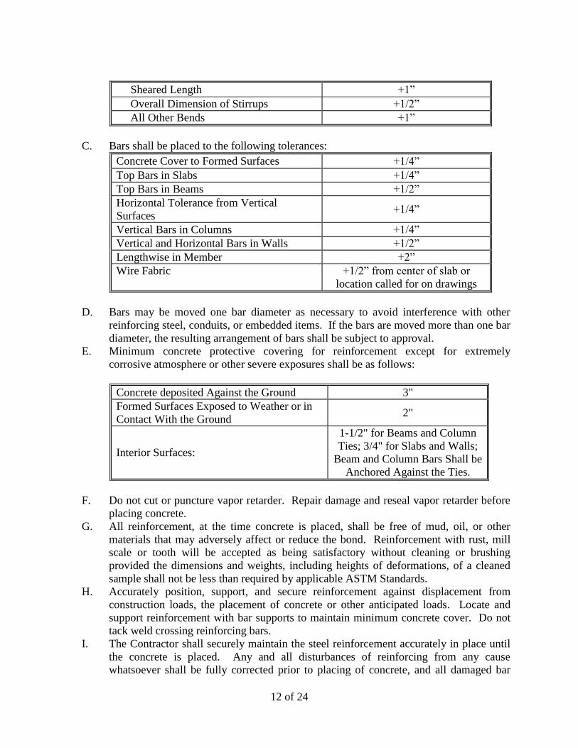
12 of 24
Sheared Length +1”
Overall Dimension of Stirrups +1/2”
All Other Bends +1”
C. Bars shall be placed to the following tolerances:
Concrete Cover to Formed Surfaces +1/4”
Top Bars in Slabs +1/4”
Top Bars in Beams +1/2”
Horizontal Tolerance from Vertical
Surfaces +1/4”
Vertical Bars in Columns +1/4”
Vertical and Horizontal Bars in Walls +1/2”
Lengthwise in Member +2”
Wire Fabric +1/2” from center of slab or
location called for on drawings
D. Bars may be moved one bar diameter as necessary to avoid interference with other
reinforcing steel, conduits, or embedded items. If the bars are moved more than one bar
diameter, the resulting arrangement of bars shall be subject to approval.
E. Minimum concrete protective covering for reinforcement except for extremely
corrosive atmosphere or other severe exposures shall be as follows:
Concrete deposited Against the Ground 3"
Formed Surfaces Exposed to Weather or in
Contact With the Ground 2"
Interior Surfaces:
1-1/2" for Beams and Column
Ties; 3/4" for Slabs and Walls;
Beam and Column Bars Shall be
Anchored Against the Ties.
F. Do not cut or puncture vapor retarder. Repair damage and reseal vapor retarder before
placing concrete.
G. All reinforcement, at the time concrete is placed, shall be free of mud, oil, or other
materials that may adversely affect or reduce the bond. Reinforcement with rust, mill
scale or tooth will be accepted as being satisfactory without cleaning or brushing
provided the dimensions and weights, including heights of deformations, of a cleaned
sample shall not be less than required by applicable ASTM Standards.
H. Accurately position, support, and secure reinforcement against displacement from
construction loads, the placement of concrete or other anticipated loads. Locate and
support reinforcement with bar supports to maintain minimum concrete cover. Do not
tack weld crossing reinforcing bars.
I. The Contractor shall securely maintain the steel reinforcement accurately in place until
the concrete is placed. Any and all disturbances of reinforcing from any cause
whatsoever shall be fully corrected prior to placing of concrete, and all damaged bar

13 of 24
supports and spaces shall be repaired or removed and replaced. All bars shall be
extended beyond stress points the development length of the bar or be provided with an
equivalent development length with a hook.
J. When required or approved, welding of reinforcing steel shall conform to AWS D1.4.
No welding shall be done at the bend in a bar. Welding of cross bars (tack welding)
shall not be permitted except as authorized or directed by the Engineer.
K. Over formwork, metal, plastic or other approved bar chairs and spacers shall be
furnished. When the concrete surface will be exposed to weather in the finished
structure or where rust would impair architectural finishes, the portions of all
accessories in contact with the formwork shall be stainless steel or plastic.
L. Unless otherwise shown on the plans and details, the following accessories shall be
provided for supports for all reinforcement:
1. Reinforced slabs-on-grade shall have plain precast concrete blocks sufficient to
support bars within prescribed tolerances, or individual high chairs with runners
to rest on soil.
2. Slab bars shall have continuous slab bolsters for bottom bars spaced a maximum
distance of 48 inches on center, and for individual high chairs spaced 48 inches
with a no.6 continuous support bar for top bars. Top bar supports shall be spaced
a maximum distance apart of 48 inches and no greater than 18 inches from the
overhanging ends of bars.
3. Beam bottom bars shall have beam bolsters spaced a maximum distance of 72
inches. Top beam bars may be supported from beam stirrups where permitted
provided beam stirrups are fabricated sufficiently accurate to permit top bars to be
placed within the tolerances permitted. Individual high chairs are required where
ties or other supports are not provided.
4. Box out all slots, chases, recesses or openings as shown on the drawings and
specifications and as required by the work of other trades. Box out for all
temporary openings such as slots, pipe spaces, etc., and build forms to seal up
when and as required. Inserts, anchors, ties, hangers, etc. shall be built into
concrete as required to secure the work of the various subcontractors. Collars,
sleeves, thimbles, anchors, sockets, etc., shall be furnished to the General
Contractor by the other subcontractors for installation in the formwork. Sleeves
shall not displace the reinforcing steel from its designated location by more than
one bar diameter unless approved by the Engineer. The Contractor shall be
responsible for the design, engineering, construction and the coordination of the
placement of items affecting each trade in the formwork.
M. Set wire ties with ends directed into concrete, not toward exposed concrete surfaces.
N. Install welded wire reinforcement in longest practicable lengths on bar supports spaced
to minimize sagging. Lap edges and ends of adjoining sheets at least 1/2 mesh plus end
extension of wires but not less than 6 inches. Offset laps of adjoining sheet widths to
prevent continuous laps in either direction. Lace overlaps with wire. Wire mesh shall
be so placed as to positively secure its position 1/3 of the slab thickness below the top
of the slab for slabs on grade.
O. Splices and offsets in reinforcements at points of maximum stress shall not be made.
All splices shall be approved, and shall provide sufficient lap to transfer the stress
between the bars by the required development length of the bars. The character and
14 of 24
design of each splice shall conform to the requirements of the ACI 318. Bars shall not
be bent after being embedded in hardened concrete, unless otherwise noted on the
drawings. Bars with kinks or bends not shown on the drawings shall not be placed.
The heating of reinforcement for bending or straightening will be permitted only if the
entire operation is approved by the Engineer.
P. Epoxy-Coated Reinforcement: Repair cut and damaged epoxy coatings with epoxy
repair coating according to ASTM D 3963. Use epoxy-coated steel wire ties to fasten
epoxy-coated steel reinforcement.
Q. The Engineer shall always be notified of the pouring schedule in advance and in ample
time prior to placement of concrete to inspect the reinforcement. Inspection of
reinforcement will be made only after each section to be poured is complete.
8. JOINTS
A. General: Construct joints true to line with faces perpendicular to surface plane of
concrete.
B. Clean joint surface of laitance, coatings, loose particles, and foreign matter to expose
aggregate. Prepare for bonding of fresh concrete to new concrete that has hardened; at
joints between foundation systems and walls dampen, but do not saturate, the roughened
and cleaned surface of set concrete immediately before placing fresh concrete. In lieu
of neat cement grout, bonding grout may be a commercial bonding agent. Apply to
cleaned concrete surfaces in accordance with the printed instruction of this bonding
material manufacturer.
C. Construction Joints: Install so strength and appearance of concrete will be least
impaired, at locations indicated or as approved by Engineer.
1. Place joints perpendicular to main reinforcement. Continue reinforcement across
construction joints unless otherwise indicated. Do not continue reinforcement
through sides of strip placements of floors and slabs.
2. Provide keyways at least 1-1/2 inches deep in all construction joints in walls,
slabs, and between walls, and foundation systems.
3. Locate joints for beams, slabs, joists, and girders near the middle of spans. Offset
joints in girders a minimum distance of twice the beam width from a beam-girder
intersection.
4. Locate horizontal joints in walls and columns at underside of floors, slabs, beams,
and girders and at the top of footings or floor slabs.
5. Space vertical joints in walls as indicated. Locate joints beside piers integral with
walls, near corners, and in concealed locations where possible.
6. Use a bonding agent at locations where fresh concrete is placed against hardened
or partially hardened concrete surfaces.
D. Contraction Joints in Slabs-on-Grade: Form weakened-plane contraction joints,
sectioning concrete into areas as indicated. Construct contraction joints for a depth
equal to at least one-fourth of concrete thickness as follows:
1. Grooved Joints: Form contraction joints after initial floating by grooving and
finishing each edge of joint to a radius of 1/8 inch. Repeat grooving of
contraction joints after applying surface finishes. Eliminate groover tool marks
on concrete surfaces.
15 of 24
2. Sawed Joints: Form contraction joints with power saws equipped with
shatterproof abrasive or diamond-rimmed blades. Cut 1/8-inch- wide joints into
concrete when cutting action will not tear, abrade, or otherwise damage surface
and before concrete develops random contraction cracks.
E. Isolation Joints in Slabs-on-Grade: After removing formwork, install joint-filler strips
at slab junctions with vertical surfaces, such as column pedestals, foundation walls,
grade beams, and other locations, as indicated.
1. Terminate full-width joint-filler strips not less than 1/2 inch or more than 1 inch
below finished concrete surface where joint sealants are indicated.
2. Install joint-filler strips in lengths as long as practicable. Where more than one
length is required, lace or clip sections together.
F. Doweled Joints: Install dowel bars and support assemblies at joints where indicated.
Lubricate or asphalt coat one-half of dowel length to prevent concrete bonding to one
side of joint.
9. WATERSTOPS
A. Flexible Waterstops: Provide PVC Waterstops in all construction joints in concrete
walls and in concrete beams and slabs. PVC waterstops shall also be provided between
concrete beams and slabs at all expansion joints to form a continuous diaphragm.
Install in longest lengths practicable. Support and protect exposed waterstops during
progress of the Work. Field fabricate joints in waterstops according to manufacturer's
written instructions.
10. SLABS ON GRADE
A. Preparation of Subgrade: The subgrade shall be well drained and of adequate and
uniform loadbearing nature. The in-place density of the subgrade soils shall be at least
the minimum required in the specifications. The bottom of an undrained granular base
course shall not be lower than the adjacent finished grade. The subgrade shall be free of
frost before concrete placing begins. If the temperature inside a building where
concrete is to be placed is below freezing, it shall be raised and maintained above 50
degrees F. long enough to remove all frost from the subgrade. The subgrade shall be
moist at the time of concreting. If necessary, it shall be dampened with water in
advance of concreting, but there shall be no free water standing on the subgrade nor any
muddy or soft spots when the concrete is placed.
B. Joints: Joints in slabs on grade shall be located as to divide the slab in areas not in
excess of 800 sq. ft. The maximum distance between joints in slabs on grade at all
points of contact between slabs on grade and vertical surfaces such as foundation walls
and elsewhere as indicated. At exposed joints, recess the premolded fill on a minimum
of ½-inch, and fill the remaining section with a joint seal and as specified herein. All
exposed construction joints in the slabs on grade shall have the edges tooled and the
crack and groove formed by the edging tool filled with a polyurethane joint sealant. No
Form-A-Key or similar metal form joints will be permitted.
16 of 24
11. CONCRETE PLACEMENT
A. Before placing concrete, the formwork installation, reinforcing steel, and items to be
embedded or cast-in must be complete. Notify other crafts involved in ample time to
permit the installation of their work; co-operate with other trades in setting such work,
as required. Notify Engineer upon completion of installation of all reinforcing and
other items in ample time to permit inspection of the work. Soil bottoms at foundation
systems are subject to testing laboratory as directed by the Engineer. Place concrete
immediately after approval of foundation excavations.
B. Before placing concrete, all equipment for mixing and transporting and placing concrete
shall be cleaned, all debris and ice removed from spaces to be occupied by the concrete,
forms thoroughly cleaned of soil, ice, or other coatings which will prevent proper bond,
reinforcement shall be securely tied in place and expansion joint material, anchors, and
other embedded items shall be securely positioned. Hardened concrete and foreign
materials shall be removed from the conveying equipment.
C. Do not add water to concrete during delivery, at Project site, or during placement unless
approved by Engineer.
1. Do not add water to concrete after adding high-range water-reducing admixtures
to mixture.
D. Place concrete in compliance with the practices and recommendations of ACI 304 or as
herein specified. Concrete shall be handled from the mixer to the place of final deposit
as rapidly as practical by methods which will prevent separation or loss of ingredients
and in a manner which will assure that the required quality concrete is obtained.
Conveying equipment shall be of size and design to insure a continuous flow of
concrete at the delivery point.
E. Concrete placed by pumping shall conform to the recommendations of ACI Publication,
"Placing Concrete by Pumping Methods."
F. Deposit concrete continuously in one layer or in horizontal layers of such thickness that
no new concrete will be placed on concrete that has hardened enough to cause seams or
planes of weakness. If a section cannot be placed continuously, construction joints shall
be located at points as provided for in the drawings or as approved. Deposit concrete as
nearly as possible to its final location to avoid segregation due to rehandling or flowing.
Do not subject concrete to any procedure which will cause segregation.
1. Deposit concrete in horizontal layers of depth to not exceed formwork design
pressures and in a manner to avoid inclined construction joints.
2. Consolidate placed concrete with mechanical vibrating equipment according to
ACI 301.
3. Do not use concrete which has become non-plastic and unworkable or does not
meet the required quality control limits, or which has become contaminated by
foreign material. Remove rejected concrete from the project site and dispose of in
an acceptable location. Consolidate concrete placed in forms by mechanical
vibrating equipment supplemented by hand-spading, rodding, and tamping.
Vibration of forms and reinforcing steel will not be permitted.
4. Screed concrete which is to receive other construction to the proper level to avoid
excessive skimming or grouting.

17 of 24
G. Do not use concrete which has become non-plastic and unworkable or does not meet the
required quality control limits, or which has become contaminated by foreign material.
Remove rejected concrete from the project site and dispose of in an acceptable location.
Consolidate concrete placed in forms by mechanical vibrating equipment supplemented
by hand-spading, rodding, and tamping. Vibration of forms and reinforcing steel will
not be permitted.
H. Concrete shall not be allowed to "freefall" a distance greater than 36 inches. All
concrete placed in columns and walls shall be placed through a tremie with the bottom
or outlet of the tremie being held at maximum of 36 inches above the surface where
concrete is being placed.
I. Deposit and consolidate concrete for floors and slabs in a continuous operation, within
limits of construction joints, until placement of a panel or section is complete.
1. Consolidate concrete during placement operations so concrete is thoroughly
worked around reinforcement and other embedded items and into corners.
2. Maintain reinforcement in position on chairs during concrete placement.
3. Screed slab surfaces with a straightedge and strike off to correct elevations.
4. Slope surfaces uniformly to drains where required.
5. Begin initial floating using bull floats or darbies to form a uniform and open-
textured surface plane, free of lumps and hollows before excess bleedwater
appears on the surface. Do not sprinkle water on the plastic surface. Do not
further disturb slab surfaces before starting finishing operations.
J. Cold-Weather Placement: Comply with ACI 306.1 and as follows. Protect concrete
work from physical damage or reduced strength that could be caused by frost, freezing
actions, or low temperatures.
1. All concrete placed in temperatures 40 degrees F. or below or exposed to
temperatures 40 degrees F. or below within five (5) days after the concrete is
placed, shall conform to the requirements of ACI 306.
2. Do not use frozen materials or materials containing ice or snow. Do not place
concrete on frozen subgrade or on subgrade containing frozen materials.
3. Do not use calcium chloride, salt, or other materials containing antifreeze agents
or chemical accelerators unless otherwise specified and approved in mixture
designs.
K. The following protection requirements for concrete placed, protected, and cured in
temperature 40 degrees F. or less shall be considered the minimum acceptable
standards.
1. Slabs, Beams: Enclose the entire perimeter of the floor below with a continuous
sheet of reinforced polyethylene or canvas. The enclosure shall be securely
fastened to the top of the outside edge of the forms of the area being protected and
to the slab or floor level immediately below the concrete being protected. The top
of the concrete surface shall be covered with either insulating blankets designed
specifically for this use, or sheets of polystyrene covered with polyethylene.
Sufficient heaters shall be placed in the enclosure below the slabs to maintain the
air temperature within all sections of the enclosure between 60 degrees F. and 70
degrees F. for a minimum period of five (5) days. Salamanders will not be
permitted.

18 of 24
2. Columns and Walls: Forms shall remain in place for a minimum of five days.
When the outside temperature falls below 32 degrees F., an insulating blanket
shall be dropped over and around the perimeter of the column or wall. These
blankets shall remain in place for a minimum period of five days.
3. Slabs on Grade: Cover top with insulating blankets. Blankets shall remain in
place for a minimum period of five days.
4. Temperature of concrete at placement shall not be less than 55 degrees F.
5. In addition to laboratory-cured test specimens, additional concrete test specimens
shall be cured under the same field conditions that the concrete in the field
represented by these cylinders is cured and high thermometers shall be placed on
the surface of slab to record daily temperatures during curing period.
L. Hot-Weather Placement: Comply with ACI 305 and as follows:
1. An approved admixture designed to retard the rate of set shall be used for all
concrete placed when temperatures exceed 75 degrees F. Set retarding
admixtures shall conform to ASTM C 494, Type D, water reducing and retarding.
2. Wet forms thoroughly before placing. Cool reinforcing by wetting sufficiently so
that steel temperatures will be nearly equal to the ambient air temperature.
3. Provide wind breaks around the perimeter of the area where concrete is being
placed.
4. Fresh concrete with temperatures 90 degrees F. or above shall be discarded off
site.
5. The amount of cement used in the job is computed for the temperature indicated
on the approved design mix. For higher concrete mix temperature, the weight of
the cement shall be increased at the rate of 12 lbs. per cubic yard for each 10
degrees F. above the concrete mix temperature.
12. FINISHING FORMED SURFACES
A. Standard Rough Form Finish: Provide a standard rough form finish to all concrete
formed surfaces that are to be concealed in the finish work or other construction.
NOTE: Interior faces of walls of water retaining structures are not considered to be
concealed. Standard rough form finish shall consist of all defective areas repaired as
specified and all holes or voids larger than 3/8 inch filled with cement grout.
B. Standard Finish for Exposed Surfaces: Provide an applied surface finish of "Thoroseal"
or an approved equal to all exposed interior and exterior concrete finishes unless
otherwise noted. Interior faces of walls of water retaining structures, including areas
which are normally submerged, are considered to be exposed surfaces and shall receive
the specified standard finish for exposed surfaces. The surface finish shall consist of
chopping and/or grinding down all high spots removing grinding of all burrs and/or
other projections, filling all voids 3/8 inch and larger, and cutting out all unsound
concrete and patching as specified herein. Before applying the finish, wet and clean the
surface of all grease, oils, efflorescence, and other foreign material. Dampen surface
immediately ahead of application. Apply the finish coat with a tampico fiber brush by
laying the finish coat on the wall in a thick coat of a minimum of 2 lbs. per sq. yard, and
brush to a uniform level surface. Do not apply in temperatures 40 degrees F or below,
or when temperatures are likely to fall below 40 degrees F within 24 hours after
19 of 24
application. The finish coat shall be mixed in strict accordance with the manufacturer's
written instructions. After the finish coat has cured, apply a finish coat of "Quick Seal"
at a minimum of 12 lb. per sq. yd. The Thoroseal shall be applied by trained
technicians.
C. Smooth Form Finish: Provide a smooth form finish for all exposed interior concrete
walls inside buildings, in pipe gallery areas, or as noted on the Drawings. Standard
form finish shall produce a smooth, hard, uniform texture on the concrete. The
arrangement of the forms and the number of seams and joints shall be kept to a
minimum. Immediately after forms are removed, cut out all unsound concrete and
patch as specified herein, and fill all pinholes and other voids larger than ¼ inch with a
cement grout. Compress mortar into voids with a firm rubber trowel or float. After
mortar dries, wipe off surface with burlap.
13. FINISHING FLOORS AND SLABS
A. General: Comply with ACI 302.1R recommendations for screeding, restraightening,
and finishing operations for concrete surfaces. Do not wet concrete surfaces.
B. Scratched Finish: After the concrete has been placed, consolidated, struck off, and
leveled to a Class C tolerance, but still plastic, the surface shall be roughened with stiff
brushes or rakes before a final set. A scratched finish shall be applied to all surfaces
which are to receive a bonded surface finish.
C. Floated Finish: After the concrete has been placed, consolidated, struck off, and leveled,
the concrete shall not be worked further until ready for floating. Floating shall begin
when the water sheen has disappeared and when the surface has stiffened sufficiently to
permit the operation. During or after the first floating, planeness of surface shall be
checked with a 10’-0” straight edge applied at not less than two different angles. All
high spots shall be cut down and all low spots filled during this procedure to produce a
surface with Class B tolerance throughout. This slab shall then be floated immediately
to a uniform sandy texture. A float finish shall be applied to all slab surfaces which are
to receive a waterproofing membrane.
D. Troweled Finish: The surface shall first be float-finished as specified. It shall next be
power troweled, and finally hand troweled. The first troweling after power floating
shall produce a smooth surface which may still show some trowel marks. Additional
troweling shall be done by hand after the surface has hardened sufficiently. The final
troweling shall be done when a ringing sound is produced as the trowel is moved over
the surface. The surface shall be thoroughly consolidated by the hand troweling
operations. The finished surface shall be essentially free of trowel marks, uniform in
texture, and appearance, and shall be planed to a Class tolerance. On surfaces intended
to support floor coverings, any defects of sufficient magnitude to show through the floor
covering shall be removed by grinding. A trowel finish shall be applied to all surfaces
which are exposed to view or are to receive a floor covering of carpet, vinyl, asbestos,
tiles, etc.
E. Broom Finish: Immediately after the concrete has received a float finish as specified in
Section B, it shall be given a coarse transverse scored texture by drawing a broom or
burlap belt across the surface. A broom finish shall be applied to all parking surfaces,
exterior concrete walks, and concrete paving slabs.
20 of 24
14. FINISHING TOLERANCE
A. Finishes with a Class C tolerance shall be true planes within ¼ inch in 24 inches as
determined by a 24-inch straight edge placed elsewhere on the slab in any direction.
Variation from level for Class A. tolerance shall not exceed ¼ inch in 10'-0" or ½ inch
maximum in any one bay between columns. Variation from level for a Class B and
Class C finish shall not exceed ¼ inch in 10'-0" or ¾ inch in any one bay between
columns.
15. CONCRETE ITEMS
A. Filling In: Fill in holes and openings left in concrete structures after work of other
trades is in place unless otherwise indicated. Mix, place, and cure concrete, as
specified, to blend with in-place construction. Provide other miscellaneous concrete
filling indicated or required to complete the Work.
B. Equipment Bases and Foundations: Provide machine and equipment bases and
foundations as shown on Drawings. Set anchor bolts for machines and equipment at
correct elevations, complying with diagrams or templates from manufacturer furnishing
machines and equipment.
16. CONCRETE PROTECTING AND CURING
A. General: Protect freshly placed concrete from premature drying and excessive cold or
hot temperatures. Comply with ACI 306.1 for cold-weather protection and ACI 305 for
hot-weather protection during curing.
B. Protect freshly placed concrete from premature drying and excessive cold or hot
temperatures, and maintain without drying at a relatively constant temperature for the
period of time necessary for hydration of the cement and proper hardening of the
concrete.
C. Curing for all horizontal slab surfaces, except those to receive a bonded finish material,
during periods when the outside air temperature does not exceed 60 degrees F. shall be
provided by applying a membrane-forming curing compound to concrete surfaces as
soon as the final troweling or floating operation has been completed. Apply uniformly
with a roller brush at a rate not to exceed 200 sq. ft. per gallon. Maintain the continuity
of the coating and repair damage to the coat during the entire curing period. Curing for
surfaces to receive a bonded finish material shall be as noted below. Curing for all
horizontal surfaces during period when the outside air temperature will exceed 60
degrees F. shall be provided by covering the entire surface with burlap. The burlap
shall be lapped 1/2 width in order to provide a double thickness of burlap. Immediately
following the placement of the burlap, the entire surface shall be maintained
continuously wet for a period of 7 days. Do not permit surfaces to dry at any period
during the required curing period.
D. Cure formed surfaces by moist curing with the forms in place for the full curing period,
or until forms are removed. If forms are removed before the curing period is complete,
apply a membrane-forming curing compound to damp surfaces as soon as the water

21 of 24
film has disappeared. Apply uniformly in continuous operation by roller brushes in
accordance with the manufacturer's directions.
E. Do not use membrane curing compounds on surfaces which are to be covered with a
coating material applied directly to the concrete or with any other cover or finish
material which shall be bonded to the concrete. These surfaces must be watercured
with a full coverage of burlap kept continuously moist for a period of 7 days.
F. During the curing period, protect concrete from damaging mechanical disturbances,
including load stresses, shocks, excessive vibration and from change caused by
subsequent construction operations.
17. JOINT FILLING
A. Prepare, clean, and install joint filler according to manufacturer's written instructions.
1. Defer joint filling until concrete has aged at least one month. Do not fill joints
until construction traffic has permanently ceased.
B. Remove dirt, debris, saw cuttings, curing compounds, and sealers from joints; leave
contact faces of joint clean and dry.
C. Install semi rigid joint filler full depth in saw-cut joints and at least 2 inches deep in
formed joints. Overfill joint and trim joint filler flush with top of joint after hardening.
18. CONCRETE SURFACE REPAIRS
A. Defective Concrete: Repair and patch defective areas when approved by Engineer.
Remove and replace concrete that cannot be repaired and patched to Engineer's
approval.
B. Repair and patch defective areas immediately after removal of forms as directed by the
Engineer. Cut out honeycombs, rock pockets, voids over ½ inch in diameter and holes
left by tie rods and bolts down to solid concrete, but in no case to a depth of less than 1
inch. Make edges of cuts perpendicular to the concrete surfaces. Expose reinforcing
steel with at least ¾ inch clearance all around. Dampen all concrete surfaces in contact
with patching concrete, and brush with a neat cement grout coating or concrete bonding
agent. Place patching concrete before grout takes its initial set. Mix patching concrete
of the same materials to provide concrete of the same type or class as the original
adjacent concrete. Place, compact, and finish as required to blend with adjacent
finished concrete. Cure in the same manner as adjacent concrete.
C. Fill holes extending through concrete by means of a plunger type gun or other suitable
device from the least exposed face to insure complete filling. Remove stains and other
discolorations that cannot be removed by cleaning for all exposed surfaces. Repair
isolated random cracks and single holes not over 1 inch in diameter by the dry-pack
method. Groove the top of cracks and cut out holes to sound concrete and clean of dust,
dirt, and loose particles. Dampen all cleaned concrete surfaces and brush with a neat
cement grout coating. Place dry-pack, consisting of 1 part Portland cement to 2-1/2
parts fine aggregate passing a no. 16 mesh sieve using only enough water as required
for handling and placing. Compact dry-pack mixture in place and finish to match the
existing surface.

22 of 24
D. Fill in holes and openings left in concrete structures for the passage of work by other
trades, unless otherwise shown or directed, after the work of other trades is in place.
Mix, place, and cure concrete as herein specified, to blend with in-place construction.
Provide all other miscellaneous concrete filling shown or required to complete work.
E. Correct high areas in unformed surfaces by grinding, after the concrete has cured at
least 14 days. Correct low areas in unformed surfaces during, or immediately after,
completion of surface finishing operations by cutting out the low areas and replacing
with fresh concrete. Finish repaired areas to blend into adjacent concrete. Proprietary
patching compounds may be used when acceptable to the Engineer.
19. FIELD QUALITY CONTROL
A. Testing and Inspecting: The Owner shall employ a concrete testing laboratory to
provide all laboratory testing services on the project and a concrete technician to
perform all quality control tests on concrete and materials used to batch concrete. The
testing agency employed shall meet the requirement of ASTM E 329.
B. Such tests will be provided and paid for by the Owner, except that tests which reveal
non-conformance with the Specifications and all succeeding tests for the same area,
until conformance with the Specifications is established shall be at the expense of the
Contractor. The Owner will be responsible for paying for only the successful tests.
C. The Contractor shall provide and maintain adequate facilities on the project for the
testing laboratory to locate the required testing equipment and for safe storage area for
test cylinders. The general contractor shall provide at his own expense all casual labor
needed to assist the concrete technician in obtaining samples of concrete and concrete
materials and moving and transporting cylinders and materials which are being tested.
D. The following services shall be performed by the designated testing agency:
1. Review and/or check-test the Contractor's proposed materials for compliance with
the specifications.
2. Review and/or check-test the Contractor's proposed mix design as required by the
Engineer.
3. Secure production samples of materials at plants or stock piles during the course
of the work and test for compliance with the specifications.
4. Conduct strength tests of the concrete during construction in accordance with the
following procedures:
a. Secure composite samples in accordance with ASTM C 172. Each sample
shall be obtained from a different batch of concrete on a random basis,
avoiding any selection of the test batch other than by a number selected at
random before commencement of concrete placement.
b. Mold and cure three specimens from each sample in accordance with
ASTM C 31. Any deviations from the requirements of this Standard shall
be recorded in the test report.
c. Test specimens in accordance with ASTM C 39. Two specimens shall be
tested at 28 days for acceptance and one shall be the average of the
strengths of the two specimens tested at 28 days. If one specimen in a test
manifests evidence of improper sampling, molding or testing, it shall be
discarded and the strength of the remaining cylinder shall be considered the
23 of 24
test result. Should both specimens in the test show any of the above
defects, the entire test shall be discarded. When high early strength
concrete is used, the specimens shall be tested at the ages indicated in the
Contract Documents.
d. Make at least one strength test for each 50 cu. yd., or fraction thereof, of
each mix design of concrete placed in any l day. When the total quantity of
concrete with a given mix design is less than 50 cu. yd., the strength test
may be waived by the Engineer if, in his judgment, adequate evidence of
satisfactory strength is provided, such as strength test results for the same
kind of concrete supplied on the same day and under comparable conditions
to other work or other projects.
5. Determine slump of the concrete sample for each strength test and whenever
consistency of concrete appears to vary, in accordance with ASTM C 143.
6. Determine air content of normal weight concrete sample for each strength test in
accordance with either ASTM C 231, ASTM C 173, or ASTM C 138 as
appropriate.
7. Determine unit weight of concrete sample for each strength test.
8. Determine temperature of concrete sample for each strength test.
9. Determine in-place strength of concrete by curing cylinders under the same field
conditions that the concrete representing these field cylinders is cured and
additionally by determining the degree/hours of curing required for the concrete
to develop the required strength for form removal.
10. Inspect concrete batching, mixing and delivery operations to the extent deemed
necessary by the Engineer.
11. Review the manufacturer's report for each shipment of cement.
E. The Contractor shall maintain an accurate log showing the following information:
1. Date of pour
2. Area poured
3. Temperature at time of pour
4. Average ambient temperature during curing period
5. Date forms scheduled for removal
6. Date form removal completed
7. Method of reshoring (number of floor, etc.)
8. Test cylinder serial numbers
9. Strength of test cylinders at 7 and 28 days.
20. EVALUATION AND ACCEPTANCE OF CONCRETE STRUCTURES
A. The concrete quality control testing as specified will be evaluated by the following
criteria:
1. Compressive strength tests for laboratory-cured cylinders will be considered
satisfactory if the averages of all sets of three consecutive compressive strength
test results equal or exceed the 28 day design compressive strength of the type of
class of concrete; and, no individual strength test falls below the required
compressive strength by more than 500 psi. If compressive strength tests fail to
24 of 24
meet these requirements, the concrete represented by these tests will be
considered deficient and subject to additional testing and/or removal.
2. Concrete work which does not conform to the specified requirements, including
strength, tolerance and finishes, shall be corrected as directed at the Contractors
expense, without extension of time therefor. The Contractor shall also be
responsible for the cost of corrections to any other work affected by or resulting
from correction to the concrete work. Core tests, if required, shall be evaluated in
accordance with the requirements of ACI 318.
3. The testing agency shall further provide quality control inspection and testing of
materials used in concrete. The following inspection and tests shall be on all
equipment and materials on a random basis:
a. Fineness modulus and gradation of sand
b. Fineness modulus and gradation of coarse aggregate.
c. Colorimetric of sand.
d. Weight per cu. ft. and percent of voids on a dry rodded basis of the coarse
aggregate.
e. Check of aggregate stock piles for contamination or intermingling of
aggregates.
f. Check of mixing equipment and trucks for compliance with ASTM C 94.
g. Absorption of stone and sand.
21. LEAK TESTING OF WATER RETAINING STRUCTURES
A. All concrete structures which will retain water or wastewater under normal operating
conditions shall be filled with water prior to backfilling and final exterior painting and
tested for leaks. Unless otherwise specified by the Engineer, the tank shall remain filled
with water for a period of seven (7) days. Any leaks, damp spots, or other defects found
shall be repaired and made water tight to the satisfaction of the Engineer. The first 48
hours of the test are utilized to allow the concrete to absorb water. After the first 48
hours of the test, the water level shall be noted and monitored for the remaining five (5)
days. A reduction in water greater than 0.1 percent per 24 hours shall be considered
excessive and shall constitute failure of the leak test. (NOTE: Rainfall and evaporation
must be considered during calculation of water loss. Rainfall shall be added to and
evaporation shall be deducted from the measured loss to determine net liquid loss.)