waterbath wtch-2006 · singlepointcontrol 1. turn on the machine, display cp (the first row cp is...
TRANSCRIPT

WATER BATH
WTCH-2006
USER MANUAL

1. GeneralThis product is automatic setting of PID algorithm without overshoot, complete function, easyto use, is the best product, analog temperature control is indispensable for medical apparatusand instruments, laboratory instruments commonly used temperature control equipment.Extensively used in Petrochemical industry, National Defense, Metallurgy, Chemical Industry,Physics, Biology Engineering, Chemistry, Pharmaceutical, life science, electronic instrument,quality inspection and measurement, plant laboratory, colleges, Research and DevelopmentInstitutes and so on.
2. Characteristics1) With complete enclosed air- cooling compressor for refrigeration, low temperaturethermostatic bath has outstanding advantages such as quick refrigeration and low noise.2) Refrigeration system is equipped with multi-purpose protection devices such as overheating, over current and so on.3) Temperature can be controlled by microcomputer, which can be operated simply, hasalarming device for temperature under low temperature limit and over high temperature limit,and is equipped with PID automatic control.4) Use double windows in red and green, upper window displays measurement value in red,and lower window displays measurement value in green, both in LCD5) Intelligent microcomputer can adjust temperature setting allowance so that digital displaydistinguish-ability reaches 0.1℃.6) Special user PID can be adjusted.7) It has internal and external cycles, external cycle will discharge thermostatic liquid insidethe bath, and establish No. 2 thermostatic bath, also it can discharge liquid outside as coolingor heating source, to lower (raise)temperature of external experimental vessels, and enlargeuse scope.
3. Technical ParametersModel No. WTCH-2006Temperature scope(℃) -20~100Temperature change range(℃) ±0.05Work bath volume(L×W×H)mm 260×200×140Open slot of work bath(L×W)mm 180×140Bath Depth(mm) 140Flow rate of Exterior cycling pumpL/min 0-20Voltage 110V/ 600Hz 1 phase

4. Operational steps:1) Add liquid media in bath, with liquid level no less than 30mm lower than work bench.2) Selection of liquid media
A.When work temperature is below 5℃,liquid media shall be alcohol.
B.When work temperature is between5℃-80℃,normally liquid media shall be pure
water.
C.When work temperature is between 80℃-90℃,normally liquid media shall be15%
glycerin water solvent.
D.When work temperature is more than 90℃ ,normally liquid media shall be oil.
3) Connection of cycling pump:
A.For connection of internal and external cycling pumps, the user only need to connect
liquid outlet tube to liquid inlet tube with hose which will be provided with the machine).
B.Connect external cycle of external cycling pump, connect liquid outlet tube to inlet of
vessel outside the bath, and connect liquid inlet tube to outlet vessel outside the bath.
(Note:tube on the left side of front panel of instrument is liquid inlet tube, and the one
on the rack panel of the instrument is liquid outlet tube).
A. Line shows:
(Figure4.1) Internal Recycle (Figure 4.3)Outlet (Figure 4.2)Outside Recycle
①Internal Recycle : Use the tube to connect the outlet and back flow (Figure4.1)②Outside Recycle: Make the outlet and back flow respectively connected to the outercontainer, set up the second temperature field (Figure 4.2)③Outlet :Direct drainage outlet (Figure 4.3)

B. Interface specification:
Figure 1:Panel Figure
4) Function of each button:
(1) Refrigeration lights: when refrigeration output light on , when refrigeration delaythe light is flickering, refrigeration closing the lights off.
(2)Circulating pump indicator light: when pump output the light on , pump closed thelight off.
(3)Heating light: when heating output the light on, heating closed the light off
(4)Water level indicator light: when the water level alarm the light on
(5)Self-tuning indicator light: Self-tuning time the light flickering.
RUN:Start and stop the operation by long press
SET:For the set value modifying, setting the parameters and modified confirmation
LEFT:Used to set data, control parameter shift
UP: Used to set data, control parameter to modify or inquire the running state ;
Long-press, inquire the environment temperature
DOWN:Used to set data, control parameter modification; Long press to view the rest of
the standard state currently running cycle number.
5) Specific operation Settings①Please put liquid medium to tank(such as silicone oil), if the instrument using higher than80℃, charging with 2 cm space should be under the rabbet, in case of high temperature oil
expansion of the overflow.②Plug the power line,turn on the switch on the back of machine.
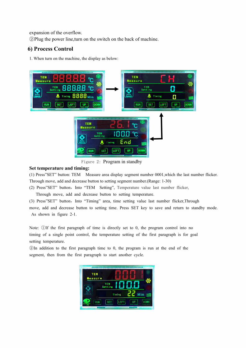
6) Process Control1. When turn on the machine, the display as below:
Figure 2: Program in standbySet temperature and timing:(1) Press”SET” button: TEM Measure area display segment number 0001,which the last number flicker.Through move, add and decrease button to setting segment number.(Range: 1-30)(2) Press”SET” button,Into “TEM Setting”, Temperature value last number flicker,
Through move, add and decrease button to setting temperature.(3) Press”SET” button,Into “Timing” area, time setting value last number flicker,Throughmove, add and decrease button to setting time. Press SET key to save and return to standby mode.As shown in figure 2-1.
Note: ①If the first paragraph of time is directly set to 0, the program control into notiming of a single point control, the temperature setting of the first paragraph is for goalsetting temperature.②In addition to the first paragraph time to 0, the program is run at the end of thesegment, then from the first paragraph to start another cycle.

Figure 2-1: Temperature,Time setting
Set parameter modification program: Press “SET” button. TEM Measure area flicker,display need to modificate segment number, press add or decrease button tomodification. Then press “SET” button to modification the temperature, time parameter.
Conversion between single point control and program control
Figure 01:Conversion between single point and program
In standby mode, press SET button and the RUN button for long time, TEM Measuredistrict display CP or CH switch back and forth, when shown as CP is the single pointcontrol, when displaying CK is the program control.

Single Point Control
1. Turn on the machine, display CP (the first row CP is single point control, the second row is empty, the third row display 1 is time-in), 3 times after the buzzer alarm,rang back to standby mode automatically.
Figure 3: single point standby mode
Setting temperature and Time.(1) Press”SET” button,Into “TEM Setting”, Temperature value last number flicker, Through move,add and decrease button to setting temperature.(2) Press”SET” button,Into “Timing” area, time setting value last number flicker,Throughmove, add and decrease button to setting time. Press SET key to save and return to standby mode.
Figure 3-1:Single point temperature and time setting
Timing FunctionWhen Timing set to 0, instrument cancel the timing function, instrument has been running;When Timing set not to 0, the meter is timing function, when the meter running time, Timming show END, buzzer, instrument to stop working, and press any key can be muted.
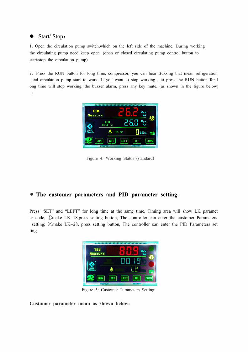
Start/ Stop:1. Open the circulation pump switch,which on the left side of the machine. During workingthe circulating pump need keep open. (open or closed circulating pump control button tostart/stop the circulation pump)
2. Press the RUN button for long time, compressor, you can hear Buzzing that mean refrigerationand circulation pump start to work. If you want to stop working , to press the RUN button for long time will stop working, the buzzer alarm, press any key mute. (as shown in the figure below):
Figure 4: Working Status (standard)
The customer parameters and PID parameter setting.
Press “SET” and “LEFT” for long time at the same time, Timing area will show LK parameter code, ①make LK=18,press setting button, The controller can enter the customer Parameterssetting; ②make LK=28, press setting button, The controller can enter the PID Parameters setting
Figure 5: Customer Parameters Setting;
Customer parameter menu as shown below:
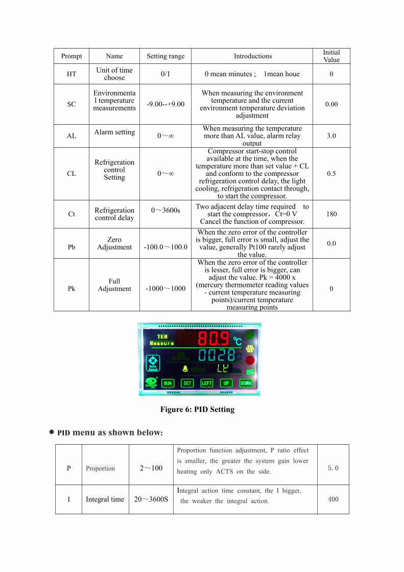
Prompt Name Setting range Introductions InitialValue
HT Unit of timechoose 0/1 0 mean minutes ; 1mean houe 0
SCEnvironmental temperaturemeasurements -9.00--+9.00
When measuring the environmenttemperature and the current
environment temperature deviationadjustment
0.00
AL Alarm setting 0~∞When measuring the temperaturemore than AL value, alarm relay
output3.0
CLRefrigeration
controlSetting 0~∞
Compressor start-stop controlavailable at the time, when the
temperature more than set value + CLand conform to the compressor
refrigeration control delay, the lightcooling, refrigeration contact through,
to start the compressor.
0.5
Ct Refrigerationcontrol delay
0~3600s Two adjacent delay time required tostart the compressor,Ct=0 V
Cancel the function of compressor.180
PbZero
Adjustment -100.0~100.0
When the zero error of the controlleris bigger, full error is small, adjust thevalue, generally Pt100 rarely adjust
the value.0.0
PkFull
Adjustment -1000~1000
When the zero error of the controlleris lesser, full error is bigger, canadjust the value. Pk = 4000 x
(mercury thermometer reading values- current temperature measuringpoints)/current temperature
measuring points
0
Figure 6: PID Setting
PIDmenu as shown below:
P Proportion 2~100
Proportion function adjustment, P ratio effectis smaller, the greater the system gain lowerheating only ACTS on the side. 5.0
I Integral time 20~3600SIntegral action time constant, the I bigger,the weaker the integral action. 400

dDerivativetime 0~3600S
Differential time constant, d is larger, thedifferential function is stronger , and canovercome the overshoot. 400
ArOvershootinhibition 0~100%
Used to suppress overshoot (Ar identified as:1.5 to 2 times the steady-state output dutycycle)
100
t Control cycle 1~100S
Silicon controlled rectifier output is commonly2 ~ 3 seconds, the remaining power of thelarger equipment dispatch T can reduce thestatic error of PID control.
3
Each parameter changes can have control effect. One minute not press the button automaticallyreturn to the standard model, may have the change of each parameter are likely to change thecontrol effect. (one minute not press X key automatically return to the standard model. May besome function parameters are not changed.
5. Precautions:1)Add liquid media into bath before using, Liquid is lower than the workbench face 30 mm can't boot,in case of burn out the heater2) Use 110V/60Hz power supply,power shall be no less than total power of instrument, and powersupply receptacle shall be earthed properly.3) Pump switch: machine on the left side of the circulation pump forced switch please don't press,unless you have special needs.If switch according to the forced circulation pump, circulating pumpwill be shut down.This fluid position in the tank temperature will be uneven, constant temperatureeffect.At this point to switch according to the forced circulation pump circulating pump4)Instrument shall be put on a place that is dry and has good ventilation, rack panel and two sides shallbe 300mm away from obstruction.5) In the process of temperature rising, there will be a frying, please get ventilation treatment. And inthe process should pay attention to, because of the high temperature will evaporate some oil, but alsopay attention to safety at this time not to touch the tank of the oil and outside circular tube, to preventburns.6)After using, all switches shall be turned off, and power plug shall be pulled out.
6. Packing list:1. main machine 1set2. power supply wire 1pc3. Rubber tube 1pc4. Cover 1pc5. Operation Manual 1copy