waterborne catalyzed fabric covering and finishing ... · and fabric covered aircraft. all of our...
TRANSCRIPT

Stewart Systems COVER Procedure Manual
Rev. #4 07/01/19
______________________________________________________________________
Waterborne Catalyzed Fabric Covering
and Finishing Procedures Manual
Stewarts Systems
8878 Harmony Church Road Johnstown, OH 43031
1-888-356-7659 (1-888-EKO-POLY) Fax: 740-967-9510
E-mail: [email protected] web: www.stewartsystems.aero

Revised by: Marty Feehan,
Edited by: Andy Humphrey
Copyright © 2019, 4th Edition July 2019
Stewart Systems 8878 Harmony Church Road
Johnstown, OH 43031
Orders: 509-782-3626 Tech Support: 740-616-0457
Fax: 740-967-9510
E-mail: [email protected]: www.stewartsystems.aero
All rights reserved. No part of this manual may be reproduced in any
form or by any means without written permission from
Stewart Systems. Printing and copying for normal use is authorized.
Stewart Systems ROR Procedure Manual
Rev. #4 07/01/19
______________________________________________________________________
The Latest in Waterborne Technology for the Aerospace Industry
C
RECORD OF REVISIONS
NO. ISSUE DATE REVISED PAGE NUMBER
CHANGE DESCRIPTION
OI 08/08/06 ------ INCORPORATED
1 1/31/08 ROR PG 1 CHANGE ROR COLUMNS TO READ REV. NO., REVISED PAGE NUMBER, CHANGE DESCRIPTION
1 1/31/08 LOEP PAGES 1,2 CHANGED DATES TO 1/31/08 FOR ROR, LOEP
AND INTRO (8 PAGES)
1 1/31/08 INTRO PAGES 1,2 CHANGED “CECONITE” TO “CECONITE, SUPERFLITE, POLY-FIBER, OR ANY OTHER POLYESTER/DACRON FABRIC WHICH IS FAA APPROVED AND MEETS THE
REQUIREMENTS OF TSO C15D/AMS 3806D.”
2 3/23/09 ALL ADDED INSTRUCTIONS FOR CONTINUED
AIRWORTHINESS, AIRWORTHINESS LIMITATIONS AND
NUMEROUS MINOR EDITORIAL CORRECTIONS
3 2/1/17 ALL CHANGED PROCESS FOR SEALING FABRIC TO INCLUDE
USE OF EKOBOND AS AN ACCEPTABLE METHOD IN
CHAPTER 10 AND NUMEROUS MINOR EDITORIAL
CORRECTIONS AND CLARIFICATIONS THROUGHOUT
4 7/1/19 ALL CHANGED PROCESS OF FILLING THE WEAVE TO EKOBOND ONLY IN CHAPTER 10. ADDED
RECOMMENDATIONS FOR PRODUCT USE AROUND
AUTO FUEL. NUMEROUS MINOR EDITORIAL
CORRECTIONS AND CLARIFICATIONS THROUGHOUT
Stewart Systems ROR Procedure Manual
Rev. #4 07/01/19
______________________________________________________________________
The Latest in Waterborne Technology for the Aerospace Industry
D
This Page Intentionally left Blank

Stewart Systems LOEP Procedure Manual
Rev. #4 07/01/19
______________________________________________________________________
The Latest in Waterborne Technology for the Aerospace Industry
E
LIST OF EFFECTIVE PAGES
SECTION PAGE ISS. DATE
COVER a-b 07/01/19 ROR c-d 07/01/19 LOEP e-f 07/01/19 TOC g-h 07/01/19
INTRO 1-4 07/01/19 1 5-8 07/01/19 2 9-10 07/01/19 3 11-14 07/01/19 4 15-16 07/01/19 5 17-18 07/01/19 6 19-28 07/01/19 7 29-32 07/01/19
8 33-34 07/01/19 9 35-36 07/01/19 10 37-42 07/01/19 11 43-46 07/01/19 12 47-52 07/01/19 13 53-54 07/01/19 14 55-60 07/01/19 15 61-62 07/01/19 16 63-64 07/01/19 17 65-67 07/01/19

Stewart Systems LOEP Procedure Manual
Rev. #4 07/01/19
______________________________________________________________________
Safe for You, Safe for your Airplane, Safe for the World
F
This Page Intentionally left Blank

Stewart Systems TOC Procedure Manual
Rev. #4 07/01/19
______________________________________________________________________
The Latest in Waterborne Technology for the Aerospace Industry
G
TABLE OF CONTENTS
Section Subject Pages Cover Stewart Systems Procedures Manual, Cover Page a-b ROR Record of Revisions c-d LOEP List of Effective Pages e-f TOC Table of Contents g-h Intro Introduction / Authorized Distributors / Limited Warranty /
Safety Information / Material Quantities 1-4
1 Preparing Surfaces for Fabric Attachment 5-8 2 Attaching Fabric to the Airframe 9-10 3 Application of EkoBond Cement 11-14 4 Calibrating Electric Irons 15-16 5 Heat Tautening of Fabric 17-18 6 Application of Reinforcing Tape & Rib Lacing 19-28 7 Application of Finish Tape 29-32 8 Application of Inspection Rings, Drain Holes & Grommets 33-34 9 Finish Ironing 35-36 10 EkoFill Application and Auto Fuel Recommendations 37-42 11 Surface Preparation for Color Coats 43-46 12 Spraying a Test Pattern 47-52 13 Primer Application 53-54 14 Color Coat Application 55-60 15 Masking for Application of Trim Colors 61-62 16 Repairing Fabric 63-64 17 FAA Approval and Compliance for Continued Airworthiness 65-67
Stewart Systems TOC Procedure Manual
Rev. #4 07/01/19
______________________________________________________________________
Safe for You, Safe for your Airplane, Safe for the World
H
This Page Intentionally left Blank

Stewart Systems INTRO Procedure Manual
Rev. #4 07/01/19
______________________________________________________________________
The Latest in Waterborne Technology for the Aerospace Industry
1
INTRODUCTION This manual is a guide in covering and finishing your fabric cover aircraft using Ceconite, Poly Fiber, SuperFlite or any other polyester/Dacron fabric which the FAA has approved and meets the requirements of TSO C15d/AMS 3806D, and all the Stewart Systems products. Instructions for continued airworthiness are contained in Section 18 of this manual. Compliance with the instructions in this manual are required. A database of all customers using Stewart Systems is maintained by Stewart Systems and the individual authorized Distributors and Dealers. We suggest that you read the entire manual prior to starting your project.
The Latest in Waterborne Technology for the Aerospace Industry
Stewart Systems offers you a single source of a complete line of revolutionary aircraft coatings that are the Finest Finishes Available, People-Safe and EPA compliant. Discover the latest in aircraft covering along with coatings that are available for metal, composite and fabric covered aircraft. All of our cements, fillers, primers and coatings are non-hazardous and non-flammable. Just as our products are ahead of their time, so is our business concept. We've been in aircraft building, maintenance, painting, and flying for over a quarter-century. We had the idea of creating one source for everything required to coat and cover aircraft. Genuine breakthroughs have been rare in aircraft coatings. In fact, there hasn't been one since the introduction of catalyzed paints over a generation ago. Until now. Finally, one of the country's leading coatings chemists has formulated a paint technology that does away with the high volatile organic compounds (VOCs) and other risk factors of today's leading conventional paints. These innovative breakthrough coatings have led the way to not only safer and easier to use products but have also improved durability and longevity over the toxic solvent-based systems. The breakthrough was the discovery of how to use water as a carrier for the solids in the coatings. Up to now, the only carriers for the resins and other solids in paints have been the old-time, high VOC solvents, with their offensive odors and the health hazards that EPA and OSHA are cracking down on, with increasing pressure. Our new, breakthrough topcoats are not "water-based" they're waterborne. Water is added only as a carrier, to reduce the viscosity of the solids to allow the coatings to be

Stewart Systems INTRO Procedure Manual
Rev. #4 07/01/19
______________________________________________________________________
Safe for You, Safe for your Airplane, Safe for the World
2
sprayed. When dry, it is impossible to distinguish between our coatings and the other two or three top solvent-based paints. Once cured, our topcoats are not only unaffected by water, they are unaffected by fuels, solvents, and even MEK. Stewart Systems is competitively priced per gallon. The cost per square foot covered is actually less. Our coatings are high in solids. With water added as a reducer you get more product. When you buy EkoPoly or EkoCrylic is comes complete with catalyst included, and water is the reducer. With solvent systems there are multiple components that must be purchased and that must be factored into the cost. There are no hazardous material shipping surcharges with our system, so it's fair to say you save a significant amount of money over top conventional paints now in volume use. Covering your aircraft can be a rewarding and enjoyable experience if you have the correct tools, materials and the knowledge you need to ensure your aircraft covering project is a success. If this is your first covering experience, there are many ways to educate yourself in regard to different covering systems and techniques. There are many videos, workshops, written information, and of course, an experienced mechanic to help guide you. If you are an experienced re-builder, you know there is no such thing as "too much information". (We have many years of accumulated covering experience and are always looking for new techniques, covering tips, tools etc.). When you complete your first project, you join a very elite group of aviation enthusiasts who can take pride in the fact that they played a great role in getting their aircraft into the air again or for the first time. Stewart Systems would like to assist you in that process. Re-covering of any certified fabric covered aircraft is to be accomplished under the authority of the Federal Aviation Administration (FAA) or a delegated authority and the appropriate records made. Specific inquiry should be made if you are in doubt about how to accomplish such a repair. Consult the Stewart Systems Procedures Manual, original aircraft specifications and FAA AC 43-13-1B. Our mission at Stewart Systems is to provide the best possible products available today and the technical support to assist our customers with their project. In addition to our fabric covering product line we offer fabric covering clinics, painting clinics, technical support via the telephone, or e-mail and a complete video series on covering. Authorized Distributors Please see our website: www.stewartsystems.aero for a current list of distributors.
Limited Warranty The information and directions for use of seller’s products represent the result of tests believed to be reliable and should be followed carefully. Due to variations in consumer

Stewart Systems INTRO Procedure Manual
Rev. #4 07/01/19
______________________________________________________________________
The Latest in Waterborne Technology for the Aerospace Industry
3
handling and methods of application, which are unknown or beyond seller’s control, seller makes no warranties, either expressed or implied, including but not limited to, any implied warranty or merchantability or fitness for a particular purpose. Buyer agrees, therefore, that the sole and exclusive remedy against seller shall be the replacement of materials or refund of the purchase price, at the option of the seller and limited to a period of one year from the date of actual purchase or delivery, whichever is sooner. Buyer agrees that no other remedy, including but not limited to incidental or consequential damages, shall be available from seller.
Safety Information Use only with adequate ventilation. Avoid breathing vapor and spray mist. Avoid contact with skin and eyes. Wash hands before and after using. Keep container closed when not in use. Use a proper OSHA approved breathing device and protective equipment during any spray painting. Do not take internally. Keep out of reach of children. For industrial use only. Refer to the Stewarts Systems Procedures Manual for the proper application and mixing instructions of the products used. Store in a cool dry place at room temperature (not to exceed 100 degrees Fahrenheit). Keep out of direct sunlight. Keep lid tight at all times. Do not allow material to freeze. Use within one year of purchase. All materials must be kept away from freezing and away from high heat. Any contaminated materials must be disposed of in an approved manner. Please read all safety warnings and precautions. Material Safety Data Sheets (MSDS) are available upon request.
Material Quantities Every effort is made to properly estimate the amount of material required for your aircraft project. The amounts arrived at are the result of the years of experience we have doing the same type of work for your aircraft type. Different users will apply and use the materials needed at rates which may be higher or lower than our experience. This is impossible to avoid as the application situations are of an almost infinite variety and the amount of material to be applied is often a “judgment call” based on the individual users’ skills and taste. As your supplier this presents somewhat of a dilemma, if we didn’t include enough material a customer might feel they were shorted and if we included too much material, they may feel we sold extra material unnecessarily. Our goal is for you to have just what you need. If your project needs a little more than originally supplied, we hope you will not think we shorted you intentionally.
Stewart Systems INTRO Procedure Manual
Rev. #4 07/01/19
______________________________________________________________________
Safe for You, Safe for your Airplane, Safe for the World
4
This Page Intentionally left Blank
Stewart Systems Section 1 Procedure Manual
Rev. #4 07/01/19
______________________________________________________________________
The Latest in Waterborne Technology for the Aerospace Industry
5
Section 1 Preparing Surfaces for Fabric Attachment Steel Surfaces – Steel must be thoroughly clean, oil free and primed with STEWART SYSTEMS Primer/Sealer (E75XX) or EkoPoxy (E76XX). All rust must be removed prior to application of primer. Light surface rust can be removed with Scotch Brite. If Mill scale or moderate to heavy rust is present, the steel should be sand blasted, and any necessary repair made, prior to the application of primer. After the surface is primed, apply STEWART SYSTEMS EkoCrylic (E5XXX) or EkoPoly (E2xxxx) topcoat. Aluminum Surfaces – Clean all surfaces with STEWART SYSTEMS EkoClean Heavy Duty Cleaner (E670), followed by STEWART SYSTEMS EkoEtch (E675). The EkoEtch may be applied while the aluminum is still wet from rinsing the STEWART SYSTEMS EkoClean Heavy Duty Cleaner. Use a red Scotch Brite pad and remove the glaze from the aluminum. Let the EkoEtch work for 3-5 minutes; do not let EkoEtch dry on the aluminum surface, rinse with clean water. Remove excess water with compressed air. Prime with STEWART SYSTEMS one-part Primer/Sealer (E75XX) or EkoPoxy (E76XX) when aluminum is completely dry, or within 12 hours of using the EkoEtch. Wood Surfaces – Apply STEWART SYSTEMS Waterborne One Part Polyurethane Clear Wood Sealer (E1800) before attaching fabric. After applying first coat of wood sealer, allow to dry, then lightly sand with 320 grit sand paper, apply second coat and let dry. The wood part may be sanded or covered without further sanding if preferred. Fiberglass Surfaces – Clean all surfaces with lacquer thinner first to remove mold, release residue, followed by STEWART SYSTEMS EkoClean Heavy Duty Cleaner (E-670) and then scuff surface with a fine abrasive pad. On bare fiberglass, after any required body work is completed, use EkoFill (E620) as your primer-filler coat. This will fill small voids and provide UV protection. Then prime with EkoPrime (E75XX) or EkoPoxy (E76XX). On gel coated fiberglass it is not necessary to use EkoFill for UV protection.

Stewart Systems Section 1 Procedure Manual
Rev. #4 07/01/19
______________________________________________________________________
Safe for You, Safe for your Airplane, Safe for the World
6
Previously Painted Surfaces- All surfaces must be clean of all oils, dirt and grime. Clean with STEWART SYSTEMS EkoClean (E670) before sanding. Scuff sand with 320 grit sand paper or Scotch Brite before coating with STEWART SYSTEMS One Part Primer/Sealer (E75XX), or EkoPoxy Primer (E76XX) Any metal surfaces previously painted or primed with other products may have new fabric attached without additional application of Stewart Systems primers or topcoats. This application is acceptable provided those non-Stewart Systems coatings have good adhesion to the metal substrate and are adequately protecting that substrate from corrosion. When applying EkoBond (E610G or E610L) to a painted or powder-coated surface, it is not necessary to scuff sand the painted surface before applying EkoBond in areas where there is a fabric-to-fabric overlap joint. If the fabric edge terminates on the painted surface, that surface must be scuff sanded with 320 sandpaper or red Scotch-Brite prior to applying EkoBond (E610G or E610L) for good adhesion. *Do not use EkoPoxy Primer on Fabric. EkoPrime may be used on fabric, metal, composite or wood. *Keep in mind that when repainting a painted surface, if you paint over a coating that is cracking or peeling, the new paint will crack and peel as well. Old paint that is cracking or peeling must be stripped or in the case of fabric, recovered. Prior to covering be certain:
1. All repairs and maintenance items have been taken care of*. 2. Inter-rib brace tape (Tape IRB) has been installed 3. All chafing areas have been protected with anti-chafe tape
One of the most important items when covering aircraft is the proper preparation of the structure. Before covering, the airframe must be inspected and approved by a FAA-certified mechanic or repair station. (AC43.13-1B)

Stewart Systems Section 1 Procedure Manual
Rev. #4 07/01/19
______________________________________________________________________
The Latest in Waterborne Technology for the Aerospace Industry
7
Primer Colors Stewart Systems EkoPrime is available in the following colors: E7510 White E7520 Smoke Grey E7525 Charcoal Grey to match EkoFill E7530 ZC Green, for the antique look Stewart Systems EkoPoxy is available in the following colors E7610 White E7620 Smoke Grey E7625 Charcoal Grey E7630 ZC Green, for the antique look

Stewart Systems Section 1 Procedure Manual
Rev. #4 07/01/19
______________________________________________________________________
Safe for You, Safe for your Airplane, Safe for the World
8
This Page Intentionally left Blank
Stewart Systems Section 2 Procedure Manual
Rev. #4 07/01/19
______________________________________________________________________
The Latest in Waterborne Technology for the Aerospace Industry
9
Section 2 Attaching Fabric to The Airframe Aircraft are usually covered by using the blanket method, or by using pre-sewn envelopes, or a combination of the two systems. Each system has its advantages and disadvantages. Blanket Application – With the blanket system, FAA approved 101, 102, or 104 Ultralight fabric is applied with cement joints usually made along the leading edges, trailing edges and fuselage surfaces overlapping on longerons and formers. In the case of wings with a chord that exceeds the width of the fabric (70”), the fabric is glued with several chord-wise seams. Then it is cemented to the trailing edge only and wrapped from the trailing edge, over the leading edge and again cemented at the trailing edge. The Blanket Application usually allows smoother surfaces over longerons and in areas where a bulky seam would show. Envelope Application - Pre-sewn fuselage envelopes will usually speed up the covering project. However, poorly fit envelopes can cause loose fabric problems. During heat tautening of envelopes, care must be taken to avoid pulling seams out of line. Bring the temperature up very slowly while tautening envelope fabric and watch the seam alignment. Envelopes are generally shipped as they are sewn (in other words, wrong side out). Be certain to turn them right side out before installing on the airframe. Check also to be sure the flap of fabric along the seam lies on the same side of the tubing to assure the smoothest surface. Be certain that the fabric is firmly attached at all points before starting the tautening process. Areas around fuel tanks, small tubing in the forward sections of a fuselage, and window frame areas are only a few of the problem areas for fabric attachment. On wings especially, you will have areas like strut openings that will stick up and create an uneven attachment to the trailing edge as you lay the fabric over the wing. In some

Stewart Systems Section 2 Procedure Manual
Rev. #4 07/01/19
______________________________________________________________________
Safe for You, Safe for your Airplane, Safe for the World
10
cases, you may have to cut a small opening in the fabric to insure a smooth trailing edge. Be sure to cut the opening only as big as you need to. If there is a surface, you can cement to around this opening do so before heat tautening the fabric. Reinforcing patches around these openings should be installed before heat tautening of the fabric as well. This will keep the opening from moving and growing from the shrinking fabric. NOTE: If you cut the opening too large, it can create a problem for you during
heat tautening of the fabric. Many times, you will have to develop special methods for attachment. Slipped fabric around these difficult areas can ruin a covering project, so use extra care.
Stewart Systems Section 3 Procedure Manual
Rev. #4 07/01/19
______________________________________________________________________
The Latest in Waterborne Technology for the Aerospace Industry
11
Section 3 Application of EkoBond Cement
Fabric to Metal - EkoBond Cement (E610G OR E610L) is used in a different manner than most aircraft cements. Apply EkoBond Cement (E610G OR E610L) to the metal surface with a bristle brush where the fabric will be attached. Let the cement tack up (tacky to the touch, approximately 5-15 minutes, depending on temperature and humidity. Ekobond can be left on the surface as long as necessary provided it’s kept clean. No need to rush). Apply the fabric to the cemented area. Using your hand, remove excess wrinkles, then with firm pressure rub fabric onto cemented areas. This will gently hold fabric in place. When fabric placement is acceptable, use a Close Quarter Iron set at 275° to 300°F and slowly make a single pass over the cemented area, using firm pressure. This will heat activate the glue and hold fabric in place. You will see a glue bond of about 1/16” to 1/8” wide where the iron heat bonded the glue. Once fabric is in place, trimmed and ready for a permanent bond, brush additional glue down through the fabric to the cemented area and wipe away excess with a blue paper shop towel while at the same time smoothing the fabric down. The cemented area should show an even color indicating a complete bond to the substrate. Drying time will depend on temperature and humidity. When installing inspection rings or reinforcing patches to bare fabric they may be wet glued. It is acceptable to install reinforcing patches or finish tapes on surfaces already coated with EkoFill, EkoPrime, or topcoat with wet glue. If it is necessary to install an inspection ring or drain grommet to a coated surface, use EkoBond Cement like contact cement: apply to both surfaces, allow to become tacky, and then press the surfaces together. NOTE: Be sure to wipe away excess cement immediately, while still wet. Fabric to Wood - When applying fabric over plywood surfaces, apply the EkoBond Cement (E610G OR E610L) to the plywood edges and allow to tack up. After shrinking the fabric, brush additional EkoBond Cement (E610G OR E610L) down through the fabric and wipe away excess with a blue paper shop towel. To remove any wrinkles, rub out or lightly iron down. NOTE: Be sure to wipe away excess cement immediately, while still wet. Keeping
glue wiped down as you go prevents unsightly glue lines.

Stewart Systems Section 3 Procedure Manual
Rev. #4 07/01/19
______________________________________________________________________
Safe for You, Safe for your Airplane, Safe for the World
12
NOTE: EkoBond Cement is thermal active, meaning that if necessary, you can ensure a good bond or reattach cemented surfaces by applying heat to the area. See: Calibrating Your Electric Irons.
Fabric to Fabric – Fabric to fabric is used on the second surface to be covered. Example: The fabric to steel would be the first surface to be covered. This should be the bottom (horizontal control surface, elevators, wings, fuselage, etc). After the first surface is in place and shrunk to its first shrink of 250°F the second surface is installed. Mark first surface with pencil line along the perimeter where the second surface will glue to. Apply EkoBond Cement (E610G OR E610L) up to this line. Let dry. Place fabric in position. This piece should be cut oversize approximately 4”. Place the fabric in position on the part and using firm pressure rub the fabric into the dried glue to lightly attach fabric in place. When satisfied with the lay of the fabric use a 275° to 300°F iron to make a single stroke over the perimeter of the glued surface to hold fabric in place. (Refer to Page 6 Section 17 for example photo) Now gently iron the fabric down to the surface of the pre glued panel to the edge of the pencil line, using the iron to shrink the fabric to a smooth surface around any corners. When the fabric is wrinkle free and smooth to the pencil line, draw a new pencil line on this lay of fabric directly over the previous pencil line. Now pull the pencil marked lay of fabric loose back to the previously bonded area where the single pass was made with the iron around the perimeter. Use pinking shears to cut off excess fabric following pencil mark. After cutting, lightly re-iron in place to remove any wrinkles. Be careful to iron only enough to hold fabric in place, but not to shrink fabric (225°-250°F). Brush EkoBond Cement (E610G OR E610L) under the fabric joint and then down through fabric into previously applied EkoBond Cement on first surface. Normally, glue about 12”, wipe excess, and glue additional 12”, and so on.

Stewart Systems Section 3 Procedure Manual
Rev. #4 07/01/19
______________________________________________________________________
The Latest in Waterborne Technology for the Aerospace Industry
13
Cemented Seams When EkoBond Cement is dry, shrink to 250°F. If additional surfaces are required (fuselage sides and top) repeat above steps. Once all surfaces are installed it is time to shrink the fabric. For cemented seams, brush a coat of EkoBond cement (E610G OR E610L) on bottom piece of fabric. When dry, place top piece of fabric in desired position. Gently press both pieces together to hold in place and with a Close Quarter Iron set at 250°F make a
single pass over the overlap seam of fabric to lock in place. (An area of approximately 1/8” wide is sufficient to lock fabric in place.) Brush EkoBond cement (E610G OR E610L) down through top piece into glue previously applied to bottom piece. Glue approximately 12” at a time, wiping off excess glue with a blue paper shop towel. Continue until seam is totally glued. Black - substrate Blue - EkoBond Lt. Red - first layer of fabric Dk. Red - second layer of fabric Cemented overlap seams will have a glue width of
at least 1”. This generally applies to areas such as glued seams on stabilizers, elevators, rudders, flaps, ailerons and longerons. Sewn seams are not necessary. Glued seams over open areas such as at transition of vertical fin to top of fuselage skin are permissible without a sewed seam. A minimum overlap seam of 1” is required with a minimum width of 2” finish tape centered over the edge of glued seam. Cemented overlap seams at wing leading edge shall be a minimum of 3”. This seam shall them be covered with a minimum of 4” wide finish tape, centered on outer edge of overlap seam. This overlap joint is acceptable over bare leading edge or over felt covered leading edge. The trailing edge shall be glued with a minimum of a 2” glued seam. This seam shall be covered with a 3” or wider finish tape. If leading edge is padded with felt the following procedure is suggested: Light weight felt that will compress to 1/32” thickness is recommended. Felt may be purchased from STEWART SYSTEMS. This material comes in 36” width and when split in half lengthwise will be wide enough to cover most leading edges. To apply, spray a light coat of 3M77 or equivalent spray adhesive to leading edge. While still damp, apply felt to leading edge and smooth out all wrinkles. Felt should now be coated with 2 brush coats of EkoBond cement to fill weave of felt. When EkoBond is dry, leading edge is ready for fabric. Note: Overlap seams are finished with a 2” or wider finish tape.

Stewart Systems Section 3 Procedure Manual
Rev. #4 07/01/19
______________________________________________________________________
Safe for You, Safe for your Airplane, Safe for the World
14
This Page Intentionally left Blank

Stewart Systems Section 4 Procedure Manual
Rev. #4 07/01/19
______________________________________________________________________
The Latest in Waterborne Technology for the Aerospace Industry
15
Section 4 Calibrating Electric Irons Accurate calibration and proper use of the electric iron is critical for a proper covering job and cannot be over emphasized. All temperatures shown in degrees Fahrenheit.
1. Select an iron with at least an 800-watt heating element, and no auto-shut off feature.
2. Use a Coverite™ surface thermometer to measure the soleplate temperature of the iron. *
*An infrared temperature gun does not read accurately on a reflective surface and therefore is not recommended for calibrating an iron used for covering.
Stewart Systems recommends and sells the Aviation Art Digital LCD Sealing Iron, a close quarter iron that holds its temperature very accurately.
For a large iron, Stewart
Systems recommends and sells the Wintersteiger Ski Wax iron. It has a digital thermostat and will not shut off during normal use. The max temperature is 356°F so it is not possible to damage the fabric. Clothes irons are not recommended for fabric covering as they are very inaccurate and can permanently damage the fabric. Good irons are well worth the investment!
3. When calibrating your iron for the first time, determine the settings on the temperature control dial, which will give you 250°F, 300°F, and 350°F. It should take you from 30 to 45 minutes to accurately determine each temperature setting. Mark each setting. If using a Wintersteiger Ski Wax iron with a digital thermostat, or a digital close quarter iron, simply verify the accuracy of the thermostat with the Coverite surface thermometer. It is not unusual for a Coverite thermometer to be off plus or minus 15 degrees. If the coverite is within 15 degrees of the digital display, it can be assumed that the iron is correct.

Stewart Systems Section 4 Procedure Manual
Rev. #4 07/01/19
______________________________________________________________________
Safe for You, Safe for your Airplane, Safe for the World
16
NOTE: Check the temperature spread across the sole plate on a new iron (not necessary on a Wintersteiger iron or digital close quarter iron). If there is a large temperature spread, you might want to try a different iron. Ideally the large center portion of the sole plate will register the desired temperature and the surrounding areas will be a few degrees above or below this temperature. At the 350°F calibration range no other parts of the sole plate should exceed 375°F.
4. While the surface thermometer is in place and the heat setting is at the
350°F mark, observe how low the temperature drops before thermostat comes back on and also how accurately the iron returns to 350°F surface temperature. Ideally this temperature spread will be 15˚F or less.
5. If a non-digital iron is dropped it must be recalibrated. *
*Using a quality iron and keeping it calibrated is extremely important. If the fabric is exposed to temperatures that exceed 375°F, permanent damage will result and may not be realized until the aircraft is put into service.
Polyester fibers crystallize at 400°F so it is very important to know your iron temperature exactly. It is a good idea to check the accuracy of your temperature marks at least once a day, as some irons tend to stray from the original settings the more they are used. The speed of travel of the iron over the surface should be around 6” per second at all temperatures. It is advisable to iron the fabric at least two times at the 250°F and 300°F temperature range, and 3 times at 350°F. This will ensure that all the surface of the fabric has been evenly shrunk and brought to full tension. The second ironing should be done at 90 degrees to the first pass. Allow extra time over ribs and any substructure as they act as a heat sink. Never start to shrink the fabric from one end. Always start at the center of the panel with a single pass, then split the difference between each end of the panel. Repeat this process until the entire panel is ironed. This is very important during the initial shrink at 250°F. When shrinking a wing panel, it is a good idea to start this process over each rib and then repeat the pattern going between each rib. This will help minimize sag between the ribs. NOTE: DO NOT use heat guns to tauten fabric. Accurate temperature control is
not possible. Burning debris from the heating elements can burn small holes in the fabric.
THE USE OF HEAT GUNS TO TAUTEN FABRIC IS PROHIBITED BY THIS STC.

Stewart Systems Section 5 Procedure Manual
Rev. #4 07/01/19
______________________________________________________________________
The Latest in Waterborne Technology for the Aerospace Industry
17
Section 5 Heat Tautening Fabric Set the iron to 250°F and perform a preliminary shrink, (smoothing the surface, but not stabilizing the fabric) over the entire fabric surface. Reference Section 4 for initial ironing procedure. Apply reinforcing patches to openings around struts, control cables, control horn, etc. with polyester canvas or fabric reinforcing patches. On wings, the first pass should be over each rib surface, then proceed to open bays between ribs. This will insure minimum sag between ribs. During the first two shrinks of fabric, it is important to get an even shrink of fabric. Do not shrink one direction only. Start at the center of the fabric and work from the center toward each end of panel in alternating steps. If shrinking an
envelope, alternate from side to side as these steps are done. Reinforcement Patches can be easily made by using fabric scraps from the covering process. Cut the reinforcing patch approximately 1” on each side larger than the opening to be reinforced. Smooth the area to be reinforced with a 250°F iron. Apply a coat of EkoBond cement to the fabric surface to same size as the patch. Apply the patch and press into place. Brush EkoBond cement down through the patch into the previously applied glue and wipe away the excess with a blue paper shop towel. These patches
are used in any areas that need to be cut open in the fabric cover such as: Rudder and aileron cable exits, quick drains, pitot tube and lift strut attach fittings. On areas such as strut fittings, cut the opening after the first shrink and let the fabric settle into place. Lightly iron the loose fabric just enough to remove the wrinkles and then apply the patch. Patches should extend 1” beyond the edges of cut out.

Stewart Systems Section 5 Procedure Manual
Rev. #4 07/01/19
______________________________________________________________________
Safe for You, Safe for your Airplane, Safe for the World
18
After attaching all the reinforcement patches and allowing to dry, set the iron to 300°F and iron the entire surface. Set the iron at 350°F for the final shrink and iron the entire surface three times, allowing the surface to cool and normalize between ironings. While heat tautening, move the iron slowly (around 6” per second) to allow the heat to maintain a constant temperature on the soleplate of the iron. Iron only to the edge of reinforcement patches and glued seams, (do not iron the patches and glued seams), alternating each ironing pass 90° to previous pass. Ultralight airframes can be damaged during the tautening of the fabric. It may not be necessary to iron fabric to the full 350° shrink on Ultralights. For conventional aircraft, with more substantial structures, the fabric should be brought up to its final tension in several temperature steps with the final tautening at 350°F. Do not be alarmed by what appears to be smoke. This is moisture and lubricant used in the fabric manufacturing process. NOTE: It is not necessary or desirable to final heat shrink fabric that has been
glued to plywood or sheetmetal surfaces.

Stewart Systems Section 6 Procedure Manual
Rev. #4 07/01/19
______________________________________________________________________
The Latest in Waterborne Technology for the Aerospace Industry
19
Section 6 Application of Reinforcing Tape & Rib Lacing Apply reinforcing tape over the ribs of the wings and control surfaces. The reinforcing tape should be the same width as the rib cap strips and extend in length at least ½” beyond any stitch. If needed, 1” long pieces of tape are used for single stitches. * Fabric is attached to cap strips in many ways: rib lacing, screws with fabric washers, rivets and wire clips. All of these methods require the use of reinforcing tape under the attaching device. Do not rely on cement to hold fabric to cap strips.
*Refer to Figures 6-1 and 6-2.
Figure 6-1
Stewart Systems Section 6 Procedure Manual
Rev. #4 07/01/19
______________________________________________________________________
Safe for You, Safe for your Airplane, Safe for the World
20
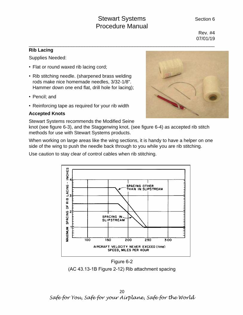
Rib Lacing Supplies Needed:
• Flat or round waxed rib lacing cord;
• Rib stitching needle. (sharpened brass welding rods make nice homemade needles, 3/32-1/8". Hammer down one end flat, drill hole for lacing);
• Pencil; and
• Reinforcing tape as required for your rib width Accepted Knots Stewart Systems recommends the Modified Seine knot (see figure 6-3), and the Staggerwing knot, (see figure 6-4) as accepted rib stitch methods for use with Stewart Systems products. When working on large areas like the wing sections, it is handy to have a helper on one side of the wing to push the needle back through to you while you are rib stitching. Use caution to stay clear of control cables when rib stitching.
Figure 6-2
(AC 43.13-1B Figure 2-12) Rib attachment spacing

Stewart Systems Section 6 Procedure Manual
Rev. #4 07/01/19
______________________________________________________________________
The Latest in Waterborne Technology for the Aerospace Industry
21
Figure 6-3 (AC 43.13-1B
Figure 2-4) Standard external modified seine knot used for single and double rib spacing.
NOTE: The first lace on a wing rib should be spaced from the leading-edge fairing no more than ½ the required rib lace spacing for the balance of the rib.

Stewart Systems Section 6 Procedure Manual
Rev. #4 07/01/19
______________________________________________________________________
Safe for You, Safe for your Airplane, Safe for the World
22
After determining rib stitch spacing and locations, using a dull pencil, mark locations. The first stitch is normally started 1" from beginning of run. Draw a perpendicular line approx. 1" across where each rib stitch location is. This will aid in finding location later. Refer to Figure 6-5. Lay down rib stitch reinforcing tape across all ribs to be stitched. Cut off the tape a minimum of 1/2” beyond the last rib stitch. Make a neat cut here because it will show through finish coat. If doing "dollar patch" rib stitches, a 1" strip of reinforcing tape should be used on each dollar patch location.
Figure 6-4 (AC 43.13-1B, Figure 2-5.) Starting stitch for rib lacing.

Stewart Systems Section 6 Procedure Manual
Rev. #4 07/01/19
______________________________________________________________________
The Latest in Waterborne Technology for the Aerospace Industry
23
Figure 6-5
Using a sharp pencil or awl, pre punch all your rib stitch holes in the fabric, immediately adjacent the ribs. Pencil is better because it leaves an easy to see hole. Use your previously made 1" pencil lines as guides. On wings, the first stitch is usually started with double square knots and double half hitches on both sides of the rib before the run begins. On tail surfaces, ailerons, and flaps, this is optional. Proceed with rib lacing process as described by AC43.13-1B. See: Figures 6-5 thru 6-13.

Stewart Systems Section 6 Procedure Manual
Rev. #4 07/01/19
______________________________________________________________________
Safe for You, Safe for your Airplane, Safe for the World
24
Figure 6-6 AC 43.13-1B Figure 2-9a Alternate sequence to tie a Modified seine knot for rib lacing.

Stewart Systems Section 6 Procedure Manual
Rev. #4 07/01/19
______________________________________________________________________
The Latest in Waterborne Technology for the Aerospace Industry
25
Figure 6-7, AC 43.13 1B Figure 2-9b Alternate sequence to tie a
Modified seine knot for rib lacing.

Stewart Systems Section 6 Procedure Manual
Rev. #4 07/01/19
______________________________________________________________________
Safe for You, Safe for your Airplane, Safe for the World
26
Figure 6-8 AC 43.13-1B Figure 2-9c Alternate sequence to tie a modified seine knot for rib lacing.
Stewart Systems Section 6 Procedure Manual
Rev. #4 07/01/19
______________________________________________________________________
The Latest in Waterborne Technology for the Aerospace Industry
27
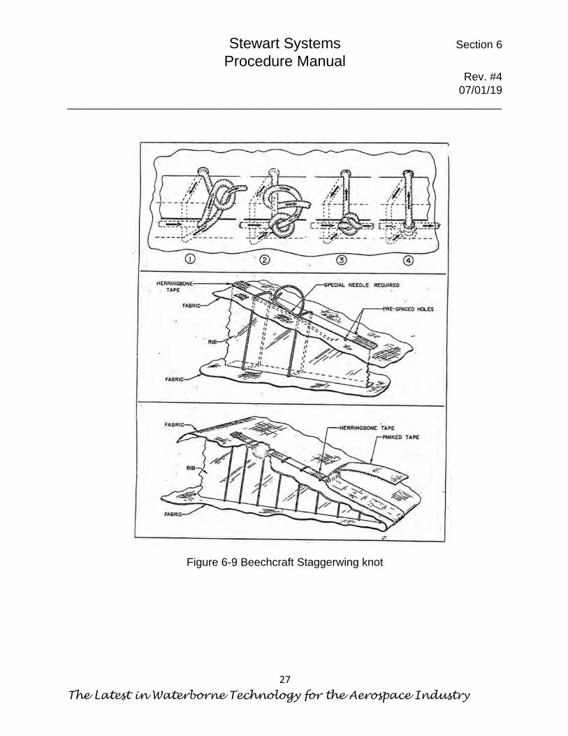
Figure 6-9 Beechcraft Staggerwing knot

Stewart Systems Section 6 Procedure Manual
Rev. #4 07/01/19
______________________________________________________________________
Safe for You, Safe for your Airplane, Safe for the World
28
For more information, see our rib lacing video posted on our web site and on YouTube
Figure 6-10 Figure 6-11
Figure 6-12 Figure 6-13

Stewart Systems Section 7 Procedure Manual
Rev. #4 07/01/19
______________________________________________________________________
The Latest in Waterborne Technology for the Aerospace Industry
29
Section 7 Application of Finishing Tape When application of reinforcing tape and rib lacing has been completed, the aircraft is ready for application of finish tapes. Try to keep finish tapes straight and even. Use a gauge the same width as the finish tape and mark the areas to be taped using a soft lead pencil. A long piece of finish tape marked in the center makes an acceptable gauge. A 2” wide strip of plastic or venetian blind about 3ft long also works well. Application on Straight Areas Apply tapes that run chord-wise first. Example, ribs, nose ribs etc. Then apply tapes that are span wise such as leading-edge tapes, trailing edge tape, etc. On wing ribs, cut finishing tape about 2” longer than required. At the leading-edge end of the rib, glue the first 2” of the finish tape with EkoBond cement (E610G or E610L). Be sure all excess cement is wiped away. Apply a tape to each rib in the same manner. NOTE: Preshrunk 2” tape is available and is recommended on the top surfaces of aircraft to be painted a dark color. Normal tapes can shrink from sitting in the sun and cause fabric at the edges of the tape to be exposed to harmful UV light. Preshrunk tapes can prevent this.
Stewart Systems Section 7 Procedure Manual
Rev. #4 07/01/19
______________________________________________________________________
Safe for You, Safe for your Airplane, Safe for the World
30
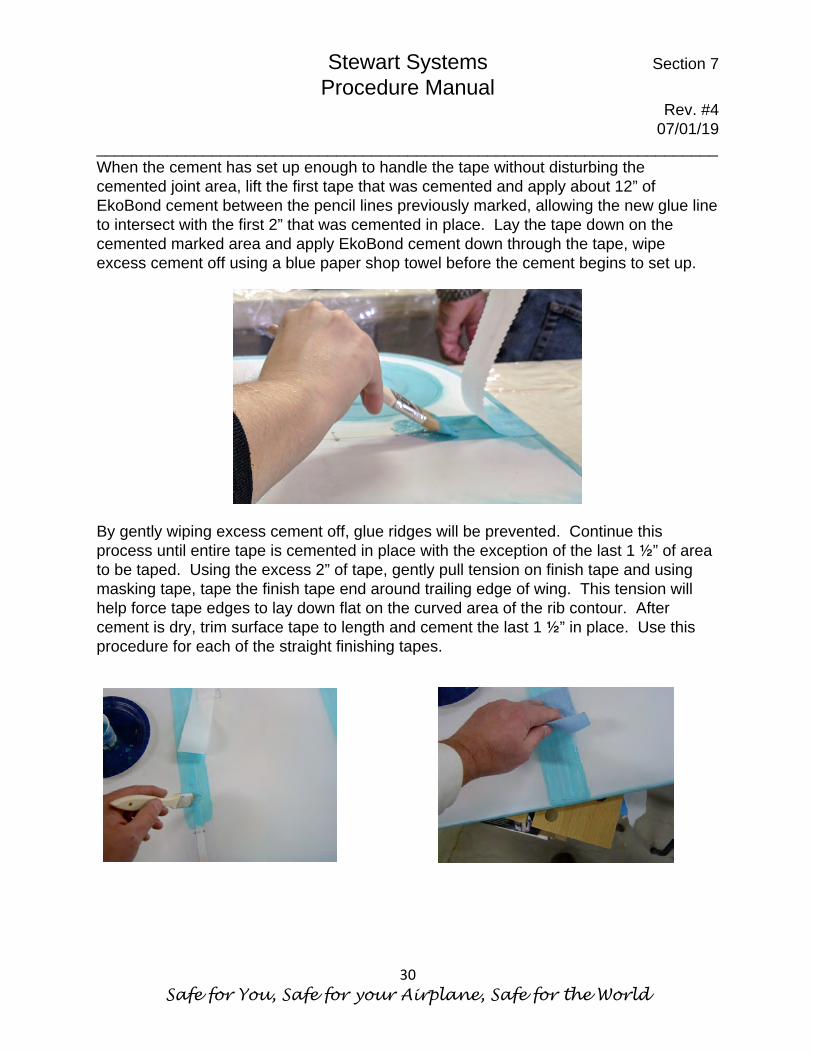
When the cement has set up enough to handle the tape without disturbing the cemented joint area, lift the first tape that was cemented and apply about 12” of EkoBond cement between the pencil lines previously marked, allowing the new glue line to intersect with the first 2” that was cemented in place. Lay the tape down on the cemented marked area and apply EkoBond cement down through the tape, wipe excess cement off using a blue paper shop towel before the cement begins to set up. By gently wiping excess cement off, glue ridges will be prevented. Continue this process until entire tape is cemented in place with the exception of the last 1 ½” of area to be taped. Using the excess 2” of tape, gently pull tension on finish tape and using masking tape, tape the finish tape end around trailing edge of wing. This tension will help force tape edges to lay down flat on the curved area of the rib contour. After cement is dry, trim surface tape to length and cement the last 1 ½” in place. Use this procedure for each of the straight finishing tapes.

Stewart Systems Section 7 Procedure Manual
Rev. #4 07/01/19
______________________________________________________________________
The Latest in Waterborne Technology for the Aerospace Industry
31
Application Around a Curve Standard finish tapes require the use of heat to form the tape smoothly around the curved areas. The sharper the curve, the more heat is required.
1. Apply a 3/8” wide strip of EkoBond Cement (E610G or E610L) to the outer perimeter of the curve.
2. Fold perimeter tape lengthwise to form a gentle crease. This gives a center line to keep the tape centered over the curved tube.
3. When cement on perimeter is tacky dry, place tape on perimeter with crease down. Starting on center of part, working toward each end, gently rub tape with hand to hold tape in place. Use a Close Quarter Iron set at 270°F and make a single pass down the center of the tape toward the ends. This will thermally bond the center of the tape to the perimeter and keep the tape from slipping.
4. With iron set at 290°F, begin working tape from middle to ends. Start in
center of tape working back and forth to the edges. This will allow tapes to shrink around the curves. Apply the same heat the entire length of the tape to assure uniform tape width. If tape will not shrink around the curve, increase the heat until proper shrink is achieved. Do not exceed 375°F.
Stewart Systems Section 7 Procedure Manual
Rev. #4 07/01/19
______________________________________________________________________
Safe for You, Safe for your Airplane, Safe for the World
32
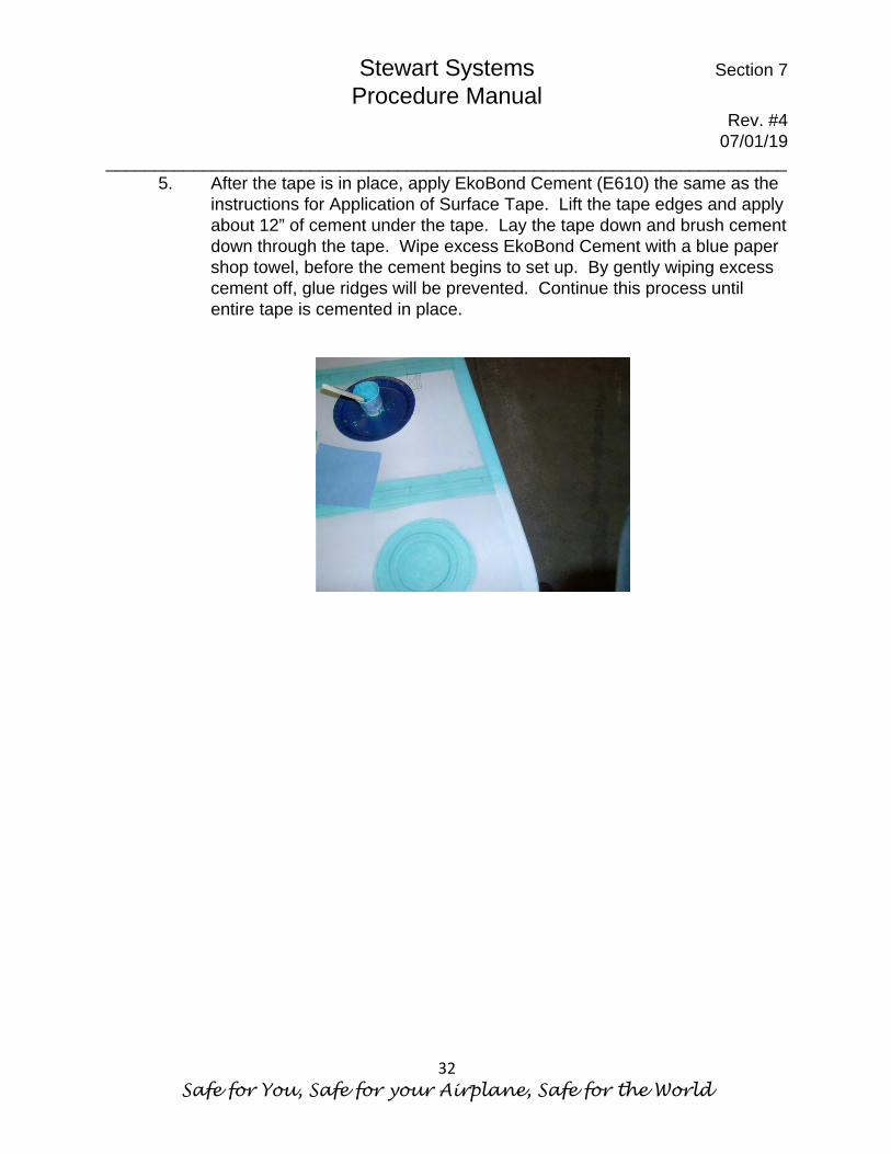
5. After the tape is in place, apply EkoBond Cement (E610) the same as the instructions for Application of Surface Tape. Lift the tape edges and apply about 12” of cement under the tape. Lay the tape down and brush cement down through the tape. Wipe excess EkoBond Cement with a blue paper shop towel, before the cement begins to set up. By gently wiping excess cement off, glue ridges will be prevented. Continue this process until entire tape is cemented in place.
Stewart Systems Section 8 Procedure Manual
Rev. #4 07/01/19
______________________________________________________________________
The Latest in Waterborne Technology for the Aerospace Industry
33
Section 8 Inspection Rings & Grommets Application of Inspection Rings -When marking locations for inspection rings, use a soft lead pencil only. It is very important that you have a good bond between the inspection ring and the fabric and between the inspection ring and the inspection ring patch. To ensure proper adhesion, follow these steps.
1. Sand tabs off the edge of inspection rings and scuff them with 320 sandpaper or red Scotchbrite for good adhesion.
2. Place the inspection ring on the fabric where it is to be located, trace the inside and outside diameters of the inspection ring onto the fabric surface.
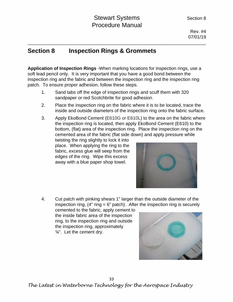
3. Apply EkoBond Cement (E610G or E610L) to the area on the fabric where the inspection ring is located, then apply EkoBond Cement (E610) to the bottom, (flat) area of the inspection ring. Place the inspection ring on the cemented area of the fabric (flat side down) and apply pressure while twisting the ring slightly to lock it into place. When applying the ring to the fabric, excess glue will seep from the edges of the ring. Wipe this excess away with a blue paper shop towel.
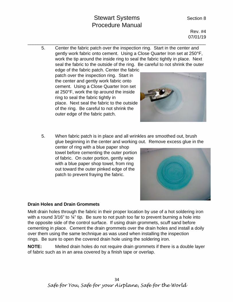
4. Cut patch with pinking shears 1” larger than the outside diameter of the
inspection ring, (4” ring = 6” patch). After the inspection ring is securely cemented to the fabric, apply cement to the inside fabric area of the inspection ring, to the inspection ring and outside the inspection ring, approximately ¼”. Let the cement dry.
Stewart Systems Section 8 Procedure Manual
Rev. #4 07/01/19
______________________________________________________________________
Safe for You, Safe for your Airplane, Safe for the World
34
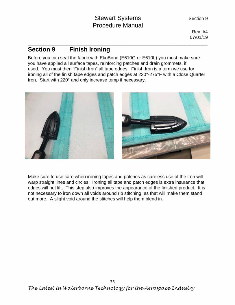
5. Center the fabric patch over the inspection ring. Start in the center and gently work fabric onto cement. Using a Close Quarter Iron set at 250°F, work the tip around the inside ring to seal the fabric tightly in place. Next seal the fabric to the outside of the ring. Be careful to not shrink the outer edge of the fabric patch. Center the fabric patch over the inspection ring. Start in the center and gently work fabric onto cement. Using a Close Quarter Iron set at 250°F, work the tip around the inside ring to seal the fabric tightly in place. Next seal the fabric to the outside of the ring. Be careful to not shrink the outer edge of the fabric patch.
5. When fabric patch is in place and all wrinkles are smoothed out, brush
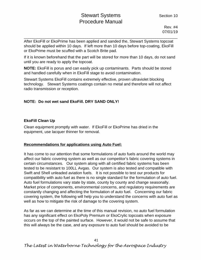
glue beginning in the center and working out. Remove excess glue in the center of ring with a blue paper shop towel before cementing the outer portion of fabric. On outer portion, gently wipe with a blue paper shop towel, from ring out toward the outer pinked edge of the patch to prevent fraying the fabric.
Drain Holes and Drain Grommets Melt drain holes through the fabric in their proper location by use of a hot soldering iron with a round 3/16” to ¼” tip. Be sure to not push too far to prevent burning a hole into the opposite side of the control surface. If using drain grommets, scuff sand before cementing in place. Cement the drain grommets over the drain holes and install a doily over them using the same technique as was used when installing the inspection rings. Be sure to open the covered drain hole using the soldering iron. NOTE: Melted drain holes do not require drain grommets if there is a double layer of fabric such as in an area covered by a finish tape or overlap.
Stewart Systems Section 9 Procedure Manual
Rev. #4 07/01/19
______________________________________________________________________
The Latest in Waterborne Technology for the Aerospace Industry
35
Section 9 Finish Ironing Before you can seal the fabric with EkoBond (E610G or E610L) you must make sure you have applied all surface tapes, reinforcing patches and drain grommets, if used. You must then “Finish Iron” all tape edges. Finish Iron is a term we use for ironing all of the finish tape edges and patch edges at 220°-275°F with a Close Quarter Iron. Start with 220° and only increase temp if necessary.
Make sure to use care when ironing tapes and patches as careless use of the iron will warp straight lines and circles. Ironing all tape and patch edges is extra insurance that edges will not lift. This step also improves the appearance of the finished product. It is not necessary to iron down all voids around rib stitching, as that will make them stand out more. A slight void around the stitches will help them blend in.

Stewart Systems Section 9 Procedure Manual
Rev. #4 07/01/19
______________________________________________________________________
Safe for You, Safe for your Airplane, Safe for the World
36
This Page Intentionally left Blank

Stewart Systems Section 10 Procedure Manual
Rev. #4 07/01/19
______________________________________________________________________
The Latest in Waterborne Technology for the Aerospace Industry
37
Section 10 Sealing the Weave Before EkoFill (E620) can be applied, the weave of the fabric must be sealed with EkoBond (E610G or E610L). (To simulate the look of cotton fabric on the inside of the aircraft use EkoBond Linen (E610L) to seal the weave.) In the past EkoFill was used to seal the weave of the fabric, but we have found that using EkoBond is both easier and provides better adhesion. EkoBond must be used on all fabric to fill the weave prior to application of EkoFill. Prior to applying EkoBond to seal the weave, the fabric should first be cleaned. Dust should be removed with a vacuum or compressed air. Next the fabric should be cleaned with EkoClean (E670) diluted at a 15:1 ratio applied with a spray bottle and a sponge. The fabric should then be rinsed with clean water. Allow the fabric to dry completely. The fabric is now ready for EkoBond application. Dilute the EkoBond with distilled water at a ratio of exactly 3 parts EkoBond to 1 part water by weight. Apply EkoBond to the fabric with a foam brush, being careful not to miss any area. Only one coat is necessary but may be brushed in multiple directions to ensure complete application. Do not wipe off excess but allow to dry. If the foam brush begins to shed small pieces of foam, use a new one. It is not necessary to apply EkoBond over areas that have been glued with EkoBond. Once EkoBond is applied, allow it to completely dry for approximately 30 minutes to 1 hour. It will be susceptible to dust and dirt because EkoBond will remain somewhat tacky even when dry. * Once the fabric is sealed with EkoBond and dry, EkoFill should be applied as soon as practical to prevent dirt and dust build up. It is acceptable to store parts for a long period of time once EkoFill has been fully applied, but care should be taken to keep it clean and dry. If the parts are to be stored it is advised to not sand the final coat of EkoFill until ready for topcoat. When ready for topcoat, wipe with a rag lightly dampened with Isopropyl alcohol prior to sanding. If the cleanliness of the surface is still in doubt, you may add an additional coat of EkoFill (E620) or EkoPrime, (E75XX) prior to top coating. *EkoBond will remain tacky indefinitely. It is possible that in areas where airframe structure is close to the backside of the fabric but not touching, if the fabric is pushed in to make contact with the structure it may adhere to it, which may be considered a

Stewart Systems Section 10 Procedure Manual
Rev. #4 07/01/19
______________________________________________________________________
Safe for You, Safe for your Airplane, Safe for the World
38
cosmetic flaw. If this is a concern, it may be prevented by applying a small area of EkoFill into the weave of the fabric first (before applying finish tape if applicable) in the area where it might make contact so that no Ekobond is exposed on the backside of the fabric. EkoFill Application STEWART SYSTEMS EkoFill (E620) when applied properly and with the minimum of 1½-to 2-mil thickness provides excellent ultraviolet light protection and gives an excellent base for finish coat colors. The minimum amount of EkoFill required is 3 cross coats. (A cross coat is defined as two individual coats; the second coat being applied 90 degrees to the first coat.) It is preferred to apply EkoFill with a spray gun, however it is acceptable to apply it with a foam brush or foam roller as well. Thoroughly mix STEWART SYSTEMS EkoFill (E620). EkoFill has a very high solids content, which may settle out in storage. Do not shake or “whip” EkoFill as it will foam or bubble. After mixing, strain EkoFill using a course 190-micron paint strainer. Spray gun setting will be the same for all sprayed coats of EkoFill. It is not necessary, or desirable to thin STEWART SYSTEMS EkoFill (E620) before spraying. HVLP spray equipment is recommended. Setting for various spray equipment will vary. The settings described here are for a Devilbiss Finishline spray gun and are a suggested starting point. Use a 1.3 mm fluid tip for best results. HVLP spray gun set-up; adjust fan control to full fan, set air pressure regulator on the spray gun to 20 to 25 psi with trigger pulled, open paint control knob ¾- 1 turn to begin. On test panel (white butcher paper works well) the spray pattern should be very light, with no wet look.

Stewart Systems Section 10 Procedure Manual
Rev. #4 07/01/19
______________________________________________________________________
The Latest in Waterborne Technology for the Aerospace Industry
39
Spray 2 cross coats allowing too dry to the touch between coats. When the second cross coat of EkoFill is thoroughly dry, iron any loose tape edges with a Close Quarter Iron set at 220°F, then lightly dry sand with 320 grit open coat sandpaper and/or a red ScotchBrite, being very careful not to “fuzz” the fabric. Under the right conditions STEWART SYSTEMS EkoFill could be ready to sand in 2 to 3 hours. Because temperature and humidity can greatly affect drying time, use the following test to determine when you are ready to sand. Choose a small area and sand lightly with 320 grit open coat sandpaper. You should create ‘sanding dust’. If the material ‘rolls up’ under the sand paper, it is not ready to sand. In high humidity conditions it is possible that EkoFill will not dry completely to the point that it will create sanding dust. Using a dehumidifier may help in these conditions. It is acceptable to sand after several hours regardless. After sanding, one additional cross coat minimum of STEWART SYSTEMS EkoFill is applied with a spray gun. Overlap your spray patterns at surface tape edges where more fill is desired. NOTE: A charcoal respirator must be worn during spray applications. STEWART SYSTEMS EkoFill should again be dry sanded with 320-400 grit open coat sandpaper. At this point the topcoat may be applied as sufficient UV protection has been achieved. However, this procedure may be repeated, as many times as

Stewart Systems Section 10 Procedure Manual
Rev. #4 07/01/19
______________________________________________________________________
Safe for You, Safe for your Airplane, Safe for the World
40
necessary to achieve the base coat and fill that you desire. The final EkoFill coat is sanded with 320-400 grit open coat sandpaper. If it is desired to add additional fill, it is acceptable to use EkoPrime (E75XX) in place of EkoFill once the minimum number of EkoFill coats have been applied. EkoPrime is easier to sand and will provide a slightly improved finish. Be careful not to add excessive coats of EkoFill and/or EkoPrime as it will add unnecessary weight and will decrease overall flexibility. NOTE: A correct application of EkoFill will not stop all visible light from showing through fabric. Three cross coats will provide very adequate UV protection. Correct EkoFill application should use 3-3.5 gallons on a Piper Cub size aircraft. NOTE: If your topcoat will be a bright white, it is highly recommended to apply one cross coat of EkoPrime White (E7510) on the EkoFill to provide a light base. (it will still be slightly grey). If your topcoat will be a light color other than white, especially yellow, it is recommended to apply one additional cross coat of EkoPrime White (E7500) to provide a white base.
The Linen System To simulate the look of cotton fabric on the interior of the aircraft, seal the weave with EkoBond Linen (E610L) instead of the green EkoBond (E610G) Once the weave of the fabric has been sealed with EkoBond Linen (E610L), one cross coat of EkoPrime White (E7510) should be applied prior to applying EkoFill. Next apply EkoFill as directed above on top of the EkoPrime.
Stewart Systems Section 10 Procedure Manual
Rev. #4 07/01/19
______________________________________________________________________
The Latest in Waterborne Technology for the Aerospace Industry
41
After EkoFill or EkoPrime has been applied and sanded the, Stewart Systems topcoat should be applied within 10 days. If left more than 10 days before top-coating, EkoFill or EkoPrime must be scuffed with a Scotch Brite pad. If it is known beforehand that the part will be stored for more than 10 days, do not sand until you are ready to apply the topcoat. NOTE: EkoFill is porus and can easily pick up contaminants. Parts should be stored and handled carefully when in EkoFill stage to avoid contamination. Stewart Systems EkoFill contains extremely effective, proven ultraviolet blocking technology. Stewart Systems coatings contain no metal and therefore will not affect radio transmission or reception. NOTE: Do not wet sand EkoFill. DRY SAND ONLY! EkoFill Clean Up Clean equipment promptly with water. If EkoFill or EkoPrime has dried in the equipment, use lacquer thinner for removal. Recommendations for applications using Auto Fuel: It has come to our attention that some formulations of auto fuels around the world may affect our fabric covering system as well as our competitor’s fabric covering systems in certain circumstances. Our system along with all certified fabric systems has been tested to be resistant to 100LL Avgas. Our system is also tested and compatible with Swift and Shell unleaded aviation fuels. It is not possible to test our products for compatibility with auto fuel as there is no single standard for the formulation of auto fuel. Auto fuel formulations vary state by state, county by county and change seasonally. Market price of components, environmental concerns, and regulatory requirements are constantly changing and affecting the formulation of auto fuel. Concerning our fabric covering system, the following will help you to understand the concerns with auto fuel as well as how to mitigate the risk of damage to the covering system. As far as we can determine at the time of this manual revision, no auto fuel formulation has any significant effect on EkoPoly Premium or EkoCrylic topcoats when exposure occurs on the top of the painted surface. However, it would not be safe to assume that this will always be the case, and any exposure to auto fuel should be avoided to be
Stewart Systems Section 10 Procedure Manual
Rev. #4 07/01/19
______________________________________________________________________
Safe for You, Safe for your Airplane, Safe for the World
42
safe. Where there currently may be an issue is when exposure to auto gas on the inside of the fabric system occurs, especially if exposed for an extended period of time. Auto fuel may soften EkoBond, and possibly loosen a tape or a glue seam. However, once the fuel leak is stopped and the fuel evaporates from the EkoBond, it generally returns to its normal state and is not affected any further from that point on. After exposure, clean thoroughly with EkoClean and inspect for any loose seams or tapes and repair as necessary. Exposure on the inside of the fabric in some cases may also cause delamintation of the EkoBond, EkoFill and therefore EkoPoly from the fabric. There are several techniques that can be used to mitigate this risk. 1) On the inside of fuel tank bays, fuselage low points and areas where fuel lines run,
seal the inside of the fabric by painting it with EkoPoly Premium. This can be sprayed if convenient but can also be brushed or rolled. If it is not possible to access the inside of the tank bay, it is acceptable to seal the weave of the bare fabric in that area with EkoPoly Premium from the outside. Clear EkoPoly Premium is the best for that application. Mix it normally as you would for a spray application, but a slightly heavier viscosity may be desired. It will need lightly scuffed before applying EkoFill for good adhesion.
2) Make sure that drain grommets are installed in low points that would allow leaked fuel to escape rather than puddle on the fabric.
3) When assembling the aircraft, test the fuel systems for leaks carefully. Run 100LL in the first tank full to check for leaks.
4) In areas near a fuel fill or vent, it is a common practice to mask the filler neck and apply EkoFill and EkoPoly premium and then remove the masking. Doing so will create a cross section that allows spilled fuel to wick into the EkoFill and may cause minor blistering around that edge. Sealing that edge with EkoPoly Premium will eliminate that possibility. Look for any other edges like that which could be exposed inadvertently to auto fuel and seal them.
Repairing an area where auto gas has affected the coatings is simple. After inspecting and repairing any affected glue joints or tapes, remove any affected coatings and clean the fabric thoroughly with EkoClean and water. Seal the weave of the fabric and apply EkoFill as described in Section 10. Sand to blend edges of old coatings and add EkoFill as necessary to hide edges. Paint to match as described in this manual.

Stewart Systems Section 11 Procedure Manual
Rev. #4 07/01/19
______________________________________________________________________
The Latest in Waterborne Technology for the Aerospace Industry
43
Section 11 Surface Preparation for Color Coats One of the main differences between solvent and waterborne paints is the method they use to attach themselves to each other. Solvent borne paints by their very nature penetrate and soften the substrate they are being applied to and solvent melts into the surface. This is called a chemical bond. Waterborne paints on the other hand rely on their ability to penetrate the surface pores and hold onto the texture of the substrate. This is called a mechanical bond. For this reason, it is very important that the substrate primer be designed for waterborne paints. Old primers and paints can lend to inferior adhesion which will result in topcoat separation after time. Steel Surfaces – All steel surfaces must be free of rust before priming and top coating All rust must be removed prior to application of primer. Light surface rust can be removed with Scotch Brite. If Mill scale or moderate to heavy rust is present the steel should be sand blasted and any necessary repairs made, then primed with STEWART SYSTEMS Primer/Sealer (E7510) Top coat with STEWART SYSTEMS Waterborne Catalyzed EkoCrylic (E5XXX) or EkoPoly Premium (E2XXXX) topcoat. . Aluminum Surfaces – Aluminum surfaces should be cleaned of all oils and dirt by first washing with STEWART SYSTEMS EkoClean Heavy Duty Cleaner (E670) to prevent possible contamination. The aluminum to be painted should then be treated with STEWART SYSTEMS EkoEtch (E675). Wearing light rubber gloves and using a red Scotch Brite pad, further wash the aluminum surface with STEWART SYSTEMS EkoEtch (E675). Follow label instructions. Do not allow the solution to dry on the aluminum surface before rinsing with clean water. The rinsed aluminum should be allowed to dry for at least 1 hour and not to exceed 12 hours before applying STEWART SYSTEMS Primer/Sealer (E7510) or EkoPoxy (E76XX). If more than 12 hours have elapsed, then re-apply STEWART SYSTEMS EkoEtch (E675) to the aluminum. Allow the STEWART SYSTEMS Primer/Sealer
Stewart Systems Section 11 Procedure Manual
Rev. #4 07/01/19
______________________________________________________________________
Safe for You, Safe for your Airplane, Safe for the World
44
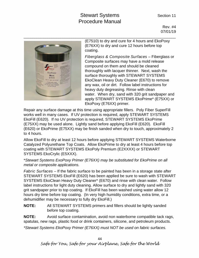
(E7510) to dry and cure for 4 hours and EkoPoxy (E76XX) to dry and cure 12 hours before top coating. Fiberglass & Composite Surfaces – Fiberglass or Composite surfaces may have a mold release compound on them and should be cleaned thoroughly with lacquer thinner. Next, wash the surface thoroughly with STEWART SYSTEMS EkoClean Heavy Duty Cleaner (E670) to remove any wax, oil or dirt. Follow label instructions for heavy duty degreasing. Rinse with clean water. When dry, sand with 320 grit sandpaper and apply STEWART SYSTEMS EkoPrime* (E75XX) or EkoPoxy (E76XX) primer.
Repair any surface damage at this time using appropriate fillers. Poly Fiber SuperFill works well in many cases. If UV protection is required, apply STEWART SYSTEMS EkoFill (E620). If no UV protection is required, STEWART SYSTEMS EkoPrime (E75XX) may be used alone. Lightly sand before applying EkoFill (E620). EkoFill (E620) or EkoPrime (E75XX) may be finish sanded when dry to touch, approximately 2 to 4 hours. Allow EkoFill to dry at least 12 hours before applying STEWART SYSTEMS Waterborne Catalyzed Polyurethane Top Coats. Allow EkoPrime to dry at least 4 hours before top coating with STEWART SYSTEMS EkoPoly Premium (E2XXXX) or STEWART SYSTEMS EkoCrylic (E5XXX). *Stewart Systems ExoPoxy Primer (E76XX) may be substituted for EkoPrime on all metal or composite applications. Fabric Surfaces – If the fabric surface to be painted has been in a storage state after STEWART SYSTEMS EkoFill (E620) has been applied be sure to wash with STEWART SYSTEMS EkoClean Heavy Duty Cleaner* (E670) and rinse with clean water. Follow label instructions for light duty cleaning. Allow surface to dry and lightly sand with 320 grit sandpaper prior to top coating. If EkoFill has been washed using water allow 12 hours dry time before top coating. (In very high humidity conditions, extra time, or a dehumidifier may be necessary to fully dry EkoFill.) NOTE: All STEWART SYSTEMS primers and fillers should be lightly sanded
before top coating. NOTE: Avoid surface contamination, avoid non waterborne compatible tack rags, spatulas, new rags, plastic food or drink containers, silicone, and petroleum products. *Stewart Systems EkoPoxy Primer (E76XX) must NOT be used on fabric surfaces.

Stewart Systems Section 11 Procedure Manual
Rev. #4 07/01/19
______________________________________________________________________
The Latest in Waterborne Technology for the Aerospace Industry
45
Stewart Systems EkoPrime (E75XX) and EkoPoxy (E76XX) are available in 4 colors: • White, • Smoke Grey, • Charcoal (matches EkoFill), and • Zinc Chromate Green.

Stewart Systems Section 11 Procedure Manual
Rev. #4 07/01/19
______________________________________________________________________
Safe for You, Safe for your Airplane, Safe for the World
46
This Page Intentionally left Blank
Stewart Systems Section 12 Procedure Manual
Rev. #4 07/01/19
______________________________________________________________________
The Latest in Waterborne Technology for the Aerospace Industry
47
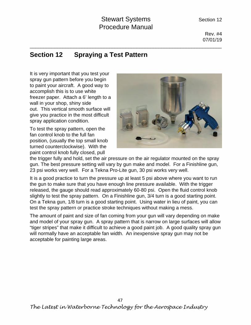
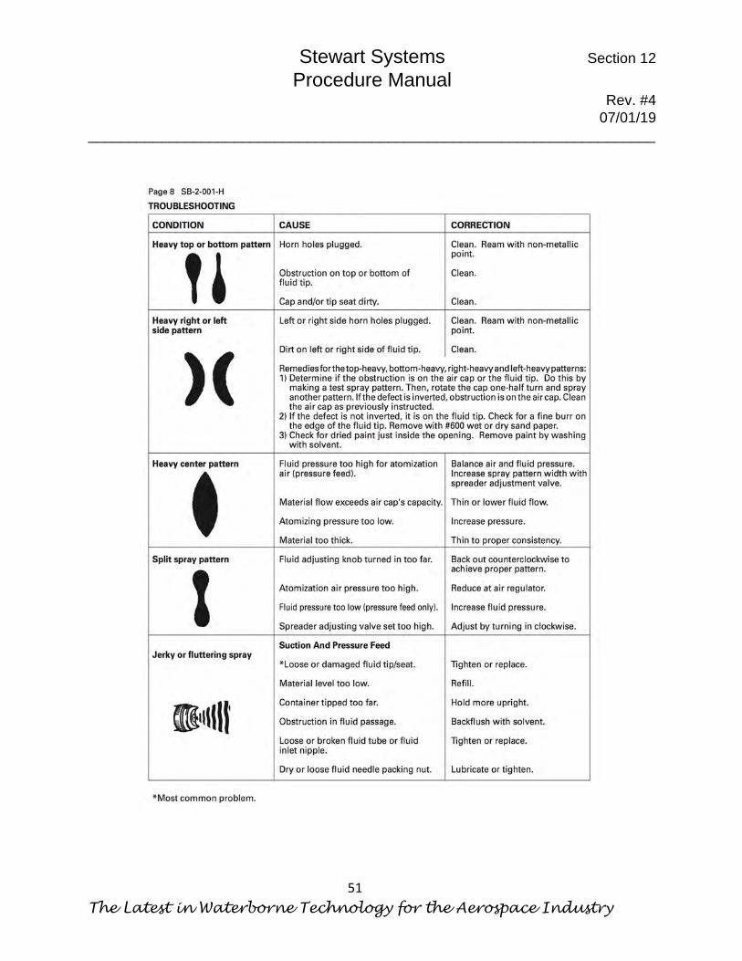
Section 12 Spraying a Test Pattern It is very important that you test your spray gun pattern before you begin to paint your aircraft. A good way to accomplish this is to use white freezer paper. Attach a 6’ length to a wall in your shop, shiny side out. This vertical smooth surface will give you practice in the most difficult spray application condition. To test the spray pattern, open the fan control knob to the full fan position, (usually the top small knob turned counterclockwise). With the paint control knob fully closed, pull the trigger fully and hold, set the air pressure on the air regulator mounted on the spray gun. The best pressure setting will vary by gun make and model. For a Finishline gun, 23 psi works very well. For a Tekna Pro-Lite gun, 30 psi works very well. It is a good practice to turn the pressure up at least 5 psi above where you want to run the gun to make sure that you have enough line pressure available. With the trigger released, the gauge should read approximately 60-80 psi. Open the fluid control knob slightly to test the spray pattern. On a Finishline gun, 3/4 turn is a good starting point. On a Tekna gun, 1/8 turn is a good starting point. Using water in lieu of paint, you can test the spray pattern or practice stroke techniques without making a mess. The amount of paint and size of fan coming from your gun will vary depending on make and model of your spray gun. A spray pattern that is narrow on large surfaces will allow “tiger stripes” that make it difficult to achieve a good paint job. A good quality spray gun will normally have an acceptable fan width. An inexpensive spray gun may not be acceptable for painting large areas.

Stewart Systems Section 12 Procedure Manual
Rev. #4 07/01/19
______________________________________________________________________
Safe for You, Safe for your Airplane, Safe for the World
48
Having clean air and a clean paint gun is of extreme importance. A high-quality filter/water separator in the system is critical. The compressed air must be cool when it gets to the filter separator in order for water to be condensed. If water is still in a vapor form it may pass through the separator and condense in the paint gun, causing flaws in the paint finish. Water contamination will show up as tiny craters in the paint surface. * If you are painting in high temperature and high humidity conditions, it may be helpful to have a refrigerated air dryer. As of the date of this manual revision a decent quality refrigerated dryer is available from Harbor Freight for about $400. It is possible to improvise by coiling a length of air hose in a bucket of ice water prior to the water separator. Be sure to dry gun with compressed air prior to assembly to avoid water contamination. It is important to have a final desiccant filter at the gun to remove any moisture that passed through the first filter separator. Also, it is imperative that the air compressor used is capable of providing 13 cfm of airflow continuously. Typically, a 5 hp compressor is required for this volume of air. It is acceptable to “Tee” two or more smaller air compressors together to achieve a combined 13 cfm or more. Many paint flaws are caused by lack of air or contaminated air.
*We have found that so far, no turbine type HVLP systems have achieved acceptable results with Stewart Systems topcoats.

Stewart Systems Section 12 Procedure Manual
Rev. #4 07/01/19
______________________________________________________________________
The Latest in Waterborne Technology for the Aerospace Industry
49
Stewart Systems Section 12 Procedure Manual
Rev. #4 07/01/19
______________________________________________________________________
Safe for You, Safe for your Airplane, Safe for the World
50
Stewart Systems Section 12 Procedure Manual
Rev. #4 07/01/19
______________________________________________________________________
The Latest in Waterborne Technology for the Aerospace Industry
51

Stewart Systems Section 12 Procedure Manual
Rev. #4 07/01/19
______________________________________________________________________
Safe for You, Safe for your Airplane, Safe for the World
52
This Page Intentionally left Blank

Stewart Systems Section 13 Procedure Manual
Rev. #4 07/01/19
______________________________________________________________________
The Latest in Waterborne Technology for the Aerospace Industry
53
Section 13 Primer Application for Metal Parts Only
STEWART SYSTEMS EkoPrime Primer/Sealer (E7510)* is best applied by first spraying a light fog coat. We recommend a 1.3 or 1.5 mm fluid tip for primer application. EkoPrime is normally used undiluted but may be thinned up to 10% with distilled water. Allow to dry until tacky, (usually about 5 minutes), spray a second medium wet coat 90° to the first coat. Allow to dry at least 30 minutes before sanding. More coats can be applied if needed to cover pits or scratches. Try not to exceed 2 mils (4 coats) for best results. Let STEWART SYSTEMS EkoPrime Primer/Sealer (E7510) cure for at least 4 hours before top coating. Topcoat must be applied within 5 days. If you wait longer than 5 days before applying the topcoat, sand the primer with 400 grit sandpaper. NOTE: Always be sure the primed surface is clean before top coating. See
Stewart Systems Metal Prep and Other Substrates Video for more tips.
*STEWART SYSTEMS EkoPoxy Primer (76XX) may be substituted for EkoPrime (E75XX) on all metal or composite applications. Follow label and/or info sheet instructions for EkoPoxy Primer. *EkoPoxy Primer (E76XX) may not be used on fabric. Stewart Systems EkoPrime (E75XX) and EkoPoxy (E76XX) are available in 4 colors:
• White, • Smoke Grey, • Charcoal (matches EkoFill), and • Zinc Chromate Green.

Stewart Systems Section 13 Procedure Manual
Rev. #4 07/01/19
______________________________________________________________________
Safe for You, Safe for your Airplane, Safe for the World
54
This Page Intentionally left Blank

Stewart Systems Section 14 Procedure Manual
Rev. #4 07/01/19
______________________________________________________________________
The Latest in Waterborne Technology for the Aerospace Industry
55
Section 14 Color Coat Application
Supplies needed:
• Clean mixing containers, appropriate sizes (do not clean containers with solvent)
• Distilled Water
• Latex gloves
• Stir Sticks
• Paint Filters
• HVLP (non-turbine) paint gun (Devilbiss Finishline or Tekna Pro-Lite recommended.)
• 1.2 to 1.4 tips for paint gun (1.3 recommended for most guns)
• Air Compressor (Recommend a minimum of 13 cfm)
• Charcoal Respirator
• Viscosity cup, Ford #4
• Digital scale for weighing paint materials
Note: 4 Easy Rules
1) Proper Mixing for Optimum Viscosity
2) Proper Spray Gun and Spray Gun Settings
3) Maintain Spray Gun Control
4) Timing Between Coats
Stewart Systems Section 14 Procedure Manual
Rev. #4 07/01/19
______________________________________________________________________
Safe for You, Safe for your Airplane, Safe for the World
56
Optimum temperature: 70° - 85° for application Mixing Paint: Prior to mixing paint you need a mixing container large enough to hold all three parts when combined with adequate room to stir.* *STEWART SYSTEMS EkoPoly Premium (E2XXXX) and EkoCrylic (E5XXX) topcoats are mixed in the exact same ratio and method. *Mixing of STEWART SYSTEMS EkoPoly Premium (E2XXXX) and EkoCrylic (E5XXX) is done by weight in grams only, not by volume. An appropriate scale may be purchased from STEWART SYSTEMS, or another source. To mix STEWART SYSTEMS EkoPoly Premium or EkoCrylic begin by setting the mixing container on the scale and zero the scale. Next, add the desired amount of part A into the container. Multiply the amount of Part A in the container by .25. This will be the amount of Part B (catalyst) you will add, as well as the approximate amount of distilled water. Next, zero the scale again and slowly pour in the appropriate amount of Part B (amount of Part A x .25) into the mixing cup, being careful not to go over the correct amount. Once the correct amount of Part B has been added, stir the mixture thoroughly for 5 minutes. Stirring mechanically with a drill may be easier and more effective. When stirring is complete, put a clean container on the scale and zero the scale. Pour in the correct amount of water (amount of Part A x .25). (Water is tricky to pour due to surface tension and is easy to go over. This is why we weigh the water in a clean container rather than directly into the paint mix). Once the correct amount of water is in the cup, pour about 75% of it into the paint mix and stir again. Allow to stand for 5 minutes before checking the viscosity. Add remainder of water as needed for desired viscosity.

Stewart Systems Section 14 Procedure Manual
Rev. #4 07/01/19
______________________________________________________________________
The Latest in Waterborne Technology for the Aerospace Industry
57
Prior to adding paint to the paint gun, check the viscosity using a Ford #4 viscosity cup. The paint mix should test at 22-24 seconds. The Ford #4 cup should test approximately 17 seconds with distilled water. Calibration of the cup should be verified prior to use.) To test viscosity, submerge viscosity cup in paint mix. As you pull the viscosity cup out of the paint mix, start a timer. The instant the stream coming from the cup breaks to drips stop the timer. When the desired viscosity is achieved, the paint mix is now ready for application. It is acceptable to vary the amount of water up or down slightly to adjust the viscosity of the mix if desired. Expect about 3-4 hours of pot life once the paint is mixed. Applying Paint: Use an HVLP non-turbine*** spray gun with 1.3 tip. (A touch up gun with 1.0 tip works well for small areas and is recommend for painting tube airframes. This will greatly reduce overspray and waste.) Be sure to run air through the paint gun before adding paint. Water from previous cleaning can make a defect in your paint finish. Pour paint mix through strainer into paint gun. Refer to Section 12 for more information on air system and paint gun setup. Setting up the HVLP spray gun: open fan to desired setting (full for large areas and narrow for small areas), set air pressure at spray gun to 20-25 psi with trigger pulled, and open fluid meter approximately ¾ turn. Be sure fluid meter knob has an index mark. If it doesn’t, make a mark on it with a felt tip pen or permanently etch a mark onto the knob.

Stewart Systems Section 14 Procedure Manual
Rev. #4 07/01/19
______________________________________________________________________
Safe for You, Safe for your Airplane, Safe for the World
58
The first coat is applied as a light fog coat. There are two ways to do this. One is with fluid meter opened less and speed of travel of spray gun slow, or with fluid meter opened more, and travel of spray gun faster. The latter works the best. Paint is too heavily applied if it “spider webs”. Open fluid control knob an additional ⅛ turn (will vary with different makes of guns). When the first coat “tacks”, usually around five (5) minutes, apply second coat 90° to first coat. To test when the paint is ready for another coat, touch the paint with your knuckle. It should be tacky, but you should not get paint transfer to your knuckle. Each successive fog coat will take longer to dry. Humidity is also a significant factor. Be patient. Third coat is applied 90° to second coat, with fluid meter opened an additional ⅛ of a turn. Apply when 2nd coat is “tacky.” Timing is not critical. It is better to wait a little too long, than not long enough. Be patient. If the paint is allowed to dry to where it is no longer tacky, allow it to fully cure and scuff sand it before adding another coat. Anytime paint is applied to cured paint that has not been scuffed, poor adhesion will result. An additional fog coat(s) may be applied as necessary to achieve full color saturation where the base color is no longer visible at all. Once color saturation is achieved on final wet coat should be applied. The number of fog coats necessary to achieve color saturation will vary due to the paint color and the base color. The wet coat will be slightly heavier than the fog coats. Enough paint should be applied so that that the paint flows into a wet look a few seconds behind the gun, but not too heavy. NOTE: If there is not sufficient tack time between fog coats or the wet coat is applied to heavy, it is possible that the paint will cure quickly on the surface while paint under the surface will off gas and create bubbles or blisters. This is commonly called “solvent pop” It may be helpful to practice painting on a vertical surface first as the paint will normally sag or run before it would blister. Depending on temperatures (70° minimum), masking may be done in 24 hours. Before applying more paint to paint that has cured, it must be scuff sanded with 320 sand paper or a red Scotch-Brite, or it will not adhere properly. NOTE: Maintain a 70° temperature during curing period of 12 hours. Pot Life: Pot Life of the paint begins once the catalyst is added to the Part A. Pot life at 75 to 85 degrees is 3-4 hours. Pot life will be longer in cooler temperatures.
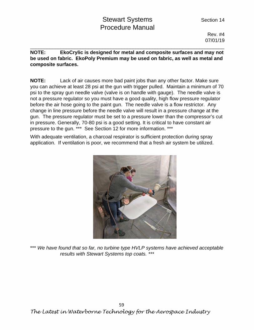
Stewart Systems Section 14 Procedure Manual
Rev. #4 07/01/19
______________________________________________________________________
The Latest in Waterborne Technology for the Aerospace Industry
59
NOTE: EkoCrylic is designed for metal and composite surfaces and may not be used on fabric. EkoPoly Premium may be used on fabric, as well as metal and composite surfaces. NOTE: Lack of air causes more bad paint jobs than any other factor. Make sure you can achieve at least 28 psi at the gun with trigger pulled. Maintain a minimum of 70 psi to the spray gun needle valve (valve is on handle with gauge). The needle valve is not a pressure regulator so you must have a good quality, high flow pressure regulator before the air hose going to the paint gun. The needle valve is a flow restrictor. Any change in line pressure before the needle valve will result in a pressure change at the gun. The pressure regulator must be set to a pressure lower than the compressor’s cut in pressure. Generally, 70-80 psi is a good setting. It is critical to have constant air pressure to the gun. *** See Section 12 for more information. *** With adequate ventilation, a charcoal respirator is sufficient protection during spray application. If ventilation is poor, we recommend that a fresh air system be utilized. *** We have found that so far, no turbine type HVLP systems have achieved acceptable
results with Stewart Systems top coats. ***
Stewart Systems Section 14 Procedure Manual
Rev. #4 07/01/19
______________________________________________________________________
Safe for You, Safe for your Airplane, Safe for the World
60
This Page Intentionally left Blank
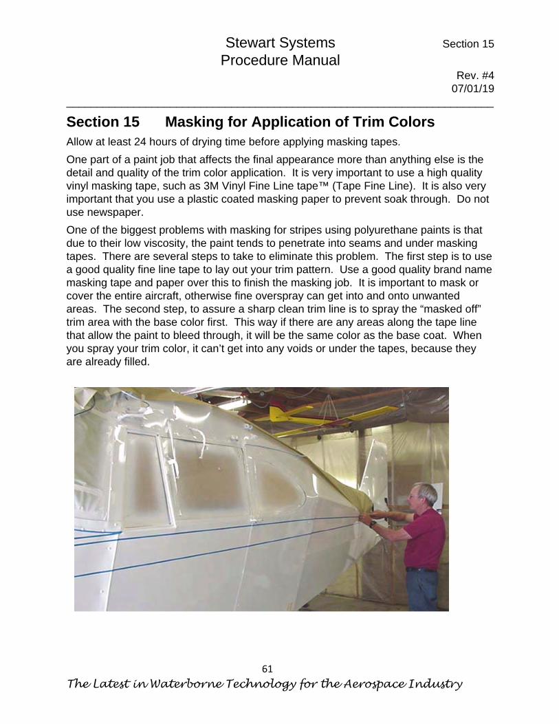
Stewart Systems Section 15 Procedure Manual
Rev. #4 07/01/19
______________________________________________________________________
The Latest in Waterborne Technology for the Aerospace Industry
61
Section 15 Masking for Application of Trim Colors Allow at least 24 hours of drying time before applying masking tapes. One part of a paint job that affects the final appearance more than anything else is the detail and quality of the trim color application. It is very important to use a high quality vinyl masking tape, such as 3M Vinyl Fine Line tape™ (Tape Fine Line). It is also very important that you use a plastic coated masking paper to prevent soak through. Do not use newspaper. One of the biggest problems with masking for stripes using polyurethane paints is that due to their low viscosity, the paint tends to penetrate into seams and under masking tapes. There are several steps to take to eliminate this problem. The first step is to use a good quality fine line tape to lay out your trim pattern. Use a good quality brand name masking tape and paper over this to finish the masking job. It is important to mask or cover the entire aircraft, otherwise fine overspray can get into and onto unwanted areas. The second step, to assure a sharp clean trim line is to spray the “masked off” trim area with the base color first. This way if there are any areas along the tape line that allow the paint to bleed through, it will be the same color as the base coat. When you spray your trim color, it can’t get into any voids or under the tapes, because they are already filled.

Stewart Systems Section 15 Procedure Manual
Rev. #4 07/01/19
______________________________________________________________________
Safe for You, Safe for your Airplane, Safe for the World
62
NOTE: When masking for trim colors, the best method is to apply regular masking tape about 1/8” from where you actually want your trim line. Then apply the fine line tap ON TOP of the regular masking. This way you can remove the fine line tape immediately after spraying the paint without the risk of masking paper coming into contact with wet paint and causing a flaw in the finish. Removal of Masking Tapes There are two methods of removing the trim tapes. One is to let the paint dry for 8 hours, remove all the masking paper and hold down tapes. Then remove the fine line tapes by pulling them off at a very sharp angle toward the trim area. This will shear the paint edge and give a very sharp distinct line. The second method is preferred by most professional shops. As soon as the wet coat is completed, immediately remove the fine line tape allowing the paint edge to flow down to a smooth edge. This method also allows you to see if any paint has bled under the masking while the paint is still wet. If yes, it can be easily removed with a lint free rag dampened with isopropyl alcohol, and a careful touch.
Stewart Systems Section 16 Procedure Manual
Rev. #4 07/01/19
______________________________________________________________________
The Latest in Waterborne Technology for the Aerospace Industry
63
Section 16 Repairing Certified & Non-Certified Fabric Always refer to FAA Advisory Circular AC 43.13-1B Chapter 2 before repairing any fabric damage. This advisory circular spells out in detail how particular injuries to the aircraft fabric are to be repaired. NOTE: STEWART SYSTEMS is certified to repair any other certified covering system using the following procedure. Repairing fabric damage with STEWART SYSTEMS method is a relatively simple and easy process. In the case of a fabric puncture, the area must be thoroughly cleaned with STEWART SYSTEMS EkoClean Heavy Duty Cleaner (E670) to remove any waxes, silicones, or contaminates which might be present. If the topcoat is STEWART SYSTEMS Waterborne Catalyzed Polyurethane, just scuff sand an area 2” around the damaged area before patching. If you are unsure of the topcoat or you know it is something other than STEWART SYSTEMS Waterborne Catalyzed Polyurethane Top Coat, you must sand through the topcoat to the primer or UV coat 2” around the damaged area. Next glue your patch on the sanded area using EkoBond glue and allow to dry completely. The glue joint must be a minimum of 1” around the perimeter. Heat shrink the fabric ONLY over the open hole under the patch. Finish Iron the patch edges at 250°F. Apply EkoFill to desired thickness, sand and spray or otherwise apply matching top coat. For more information, refer to previous sections of this manual. Spraying Repaired Areas When repainting a repair, whether it is on fabric or metal, it is always best if you can paint to normal physical boundaries such as between ribs, stringers, seam lines or hinge lines. In this way the new paint line can be somewhat hidden. If it is impractical to paint to a normal boundary, spot painting can be accomplished with just a little extra work. First, mask the area around the repair area to be painted. DO NOT USE FINE LINE TAPE. Give yourself 4 – 6 inches beyond the repaired area to paint. Turn up the inside edges of the masking tape about 1/8”. This prevents an abrupt paint edge out in the middle of nowhere. Apply the paint as you normally would. After the paint has dried and the masking tape and paper have been removed you will notice there is a dusty dry area where the new paint meets the old paint. After the new paint has cured for 7 days you can then buff out this area using regular buffing compound to blend the new and the old paint together. * According to FAR part 43 Appendix A, a fabric repair consisting of an area greater than three bays of the wing, or an entire control surface is considered a major repair and will require a Form 337.

Stewart Systems Section 16 Procedure Manual
Rev. #4 07/01/19
______________________________________________________________________
Safe for You, Safe for your Airplane, Safe for the World
64
This Page Intentionally left Blank

Stewart Systems Section 17 Procedure Manual
Rev. #4 07/01/19
______________________________________________________________________
The Latest in Waterborne Technology for the Aerospace Industry
65
Section 17 FAA APPROVAL AND COMPLIANCE FOR CONTINUED AIRWORTHINESS
This information is offered to assist in returning the aircraft to service. Compliance or approval under the referenced STC requires strict adherence to the Stewart Systems Procedures Manual including the use of Stewart Systems materials approved for such use under a Parts Manufacturer Approval (PMA). Deviation from approved procedures and/or substitution of other materials violates both Federal Regulations and this Supplementary Type Certificate (STC). For an aircraft or component listed on the STC Certificate of Eligibility the repair and return to service is handled in the normal manner. A certified mechanic must fill out the FAA Form 337 and make the corresponding entries in the aircraft log book. The entries must state that the repair or covering was performed in accordance with the Stewart Systems Procedures Manual; Revision and Date noted and under the STC referenced herein. The aircraft must be inspected and returned to service by an FAA representative or delegated authority with an Inspection Authorization (IA). For an aircraft or component not yet listed on the FAA Approved Model List No. STC SA01734SE, please fill out the Stewart Systems Installation Report on page 3. The mechanic who completed the work should complete this form and sign it. The form should be sent to: Stewart Systems, 8878 Harmony Church Rd. Johnstown, OH 43031. Stewart Systems will obtain approval for your aircraft from the FAA and mail a copy of this approval to you. This approval must be kept in your aircraft maintenance records as proof of applicability of this STC to your aircraft. The aircraft cannot be returned to service until the amended AML showing the aircraft model is received. As an alternative one can request a field approval from local FAA authorities. Granting of this varies from location to location but it is usually possible. Instructions for continued airworthiness:
1. Inspect the aircraft fabric covering as per AC 43-13-1B, Chapter 3, Section 2-34.
2. Clean fabric on a regular basis using a mild soap and water solution rinsing thoroughly thereafter.
3. Use a good wax to maintain cosmetic appearance as necessary. 4. Make fabric covering repairs per Stewart Systems Procedures Manual, Section
16: “Repairing Fabric” Procedures. NOTE: Make a copy of this information and attach to airframe log.

Stewart Systems Section 17 Procedure Manual
Rev. #4 07/01/19
______________________________________________________________________
Safe for You, Safe for your Airplane, Safe for the World
66
Make an entry in the remarks section of FAA form 337. ICA as addressed in the Stewart Systems Procedures Manual with the latest Revision Number Used.
Airworthiness Limitations The Airworthiness Limitations Section is FAA approved and specifies maintenance required under 14CFR secs. 43.16 and 91.403 unless an alternative program has been approved. There are no changes to the existing airworthiness limitations associated with this modification. If an aircraft is not listed on the Stewart Systems FAA Approved Model List, please contact Stewart Systems.
Stewart Systems Section 17 Procedure Manual
Rev. #4 07/01/19
______________________________________________________________________
The Latest in Waterborne Technology for the Aerospace Industry
67
STEWART SYSTEMS INSTALLATION REPORT
I certify that fabric covered surfaces on the follow aircraft has been recovered in
accordance with STC 01734AE the Stewart Systems Procedure Manual. No problems
were noted during installation.
Aircraft Make:____________________________________
Aircraft Model:____________________________________
Aircraft Registration Number ________________________
Aircraft Type Certificate Number______________________
Date of Installation Completion_______________________
Components Recovered:______________________________________
__________________________________________________________
_______________________________________ Signatare & Date _______________________________________ Printed Name _______________________________________ Address _______________________________________ _______________________________________ _______________________________________ Phone