waterjet techniques for composite- material jet engine
TRANSCRIPT

QUEST Technical Report No. 716
WATERJET TECHNIQUES FOR COMPOSITE- MATERIAL JET ENGINE COMPONENT REPAIR
C. Dunsky, P. Tacheron, and M. Hashish
June 1996
Phase I SBIR Final Report Prepared for
NAVAL AIR WARFARE CENTER Under Contract No. N00421-95-C-1141
Approved for public release; SBIR report, distribution unlimited.
QUEST INTEGRATED, INC. 21414 - 68th Avenue South Kent, Washington 98032
(206)872-9500
7 014

QUEST Technical Report No. 716
WATERJET TECHNIQUES FOR COMPOSITE- MATERIAL JET ENGINE COMPONENT REPAIR
C. Dunsky, P. Tacheron, and M. Hashish
June 1996
Phase I SBIR Final Report Prepared for
NAVAL AIR WARFARE CENTER Under Contract No. N00421-95-C-1141
Approved for public release; SBIR report, distribution unlimited.
QUEST INTEGRATED, INC. 21414 - 68th Avenue South Kent, Washington 98032
(206) 872-9500

Waterjet Techniques for Composite-Material Jet Engine Component Repair
PROJECT SUMMARY This Phase I SBIR project investigated the feasibility of using abrasive-waterjet (AWJ) machining technologies for the repair of jet engine components fabricated from composite materials. Increasing use of such materials in aircraft engine blades and vanes poses challenges for the repair of foreign object damage, because techniques used to repair metal parts are not generally applicable to composites. In recent years, ultrahigh-pressure AWJ cutting technology has advanced to encompass precision machining processes such as drilling, milling, and turning. This project investigated the use of AWJ milling techniques to remove precise amounts of composite material without damage such as delamination or fiber pullout. The concept offers the potential for the removal of damaged sections of composite blades and vanes and high-precision preparation of the affected area preparatory to bonding or fastening of patching material. Due to the thinness of the material layers removed with each pass of the AWJ, more precise control of the machined surface contour is possible than is typically achieved using current manual composite shaping techniques.
In cooperation with General Electric Aircraft Engines, two composite materials were selected for the Phase I testing. These included a structural graphite-epoxy and a proprietary composite consisting of quartz fibers in PMR-15 resin matrix. An existing in-house AWJ milling system was adapted for precision shape milling of composites. Parametric tests were then conducted to identify operating conditions at which damage to the two materials occurred. This was followed by measurements of the material removal rates for the two materials, as a function of the nozzle/workpiece relative speed. Once this data was acquired, precision shape milling routines were created by programming the motion pattern of the AWJ nozzle over the workpiece surface.
A spreadsheet-based procedure was developed utilizing the material removal rate data for each of the two composites under consideration, the AWJ process parameters, and the desired finished geometry. The spreadsheet output consisted of a list of movement commands for the AWJ nozzle manipulator stage.
Two common composite repair geometries were selected for the Phase I study, including low-angle straight-scarf joints and stepped-lap joints. For the straight-scarf geometry, the objective was to machine two walls sloped at a 6-degree angle with a flat-bottomed pocket between them. Demonstration parts were produced with the desired pocket lengths and depths and wall angles of 5.0 to 6.0 degrees. For the stepped-lap geometry, the objective was to machine a series of steps with heights equal to the thickness of a single composite ply, typically 0.007-0.008 inch. Part masking techniques were developed to ensure that sharp edges could be maintained at both inside and outside step corners, and uniform steps were suc- cessfully machined in both materials of interest with heights deviating from the ply thickness by no more than 0.001 inch. For both the straight-scarf and stepped-lap geometries, mating parts were machined in one of the two composite materials, representing patches that could be bonded to the machined pockets.
The ability that was demonstrated in Phase I to accurately predict and control the material removal profile indicates that this technique can find wide application in precision shaping of aerospace com- posites. Precision repair operations on composite propulsion and airframe components will therefore be possible and can be automated with the development of proper nozzle motion control hardware and software. More generally, the technology offers the possibility for cost-effective near-net shaping and machining of composites in a variety of applications, including automotive, energy conversion, and advanced optical manufacturing.
TR-716/06-96 i

TABLE OF CONTENTS
PROJECT SUMMARY i
LIST OF FIGURES iii
LIST OF TABLES iv
1. INTRODUCTION 1
2. TECHNICAL BACKGROUND 2
2.1 Composites in Aircraft Engine Components 2
2.2 AWJ Machining Technology 4
2.2.1 AWJ Cutting 4
2.2.2 Advanced AWJ Machining Applications 5
3. OBJECTrVES OF PHASE I PROGRAM 8
4. TECHNICAL APPROACH 9
5. PHASE I ACTIVITIES 10
5.1 Survey of Existing Repair Methods and Definition of Phase I Work 10
5.1.1 Composite Components on Existing and Near-Term GEAE Engines 11
5.1.2 Recommendations for Development of AWJ Repair Techniques 12
5.2 Stepped-Lap Joints 14
5.3 Test Bed Preparation 15
5.4 Milling Rates 17
5.5 Jet Motion Control Scheme 21
5.6 Milling of Straight-Scarf Geometry 22
5.7 Milling of Stepped-Lap Geometry 27
5.8 Two-Dimensional Pocket Machining 30
5.8.1 AWJ Machining 30
5.8.2 Microblaster Machining 31
6. CONCLUSIONS AND RECOMMENDATIONS 33
REFERENCES 34
REPORT DOCUMENTATION PAGE - SF298 35
TR-716/06-96

LIST OF FIGURES
Figure 1. Early Experimental Graphite Fiber-PMR-15 2 Ultrahigh-Speed Fan Blade
Figure 2. Graphite Fiber - PMR-15 Structural Components for Military Engines 3
Figure 3. Graphite Fiber - PMR-15 Components Evaluated for Turbojet and Turbofan Engines 3
Figure 4. AWJ Nozzle and Process Parameters 4
Figure 5. Examples of Advanced AWJ Machining Applications 6
Figure 6. Typical Joint Designs Used in Composite Repair 13
Figure 7. Straight-Tapered Scarf Joint Geometry for a 0/45/90/-45 Composite Lay-up 13
Figure 8. Stepped-Lap Joint Geometry for a 0/45/90/-45 Composite Lay-up 14
Figure 9. Typical AWJ Milling Configurations 15
Figure 10. Radial Milling Setup 16
Figure 11. Cylindrical Milling Setup 17
Figure 12. Initial Pressure and Speed Sensitivity Tests 19
Figure 13. Dependence of Material Removal Rate on Workpiece Surface Speed for Graphite-Epoxy...20
Figure 14. Dependence of Material Removal Rate on Workpiece Speed for GEAE Astroquartz 20
Figure 15. AWJ Nozzle Motion Pattern for Controlled Milling of Single-Scarf Angle 21
Figure 16. Header Section of AWJ Motion-Profiling Spreadsheet for a 6-Degree Scarf Angle 23 in Graphite-Epoxy
Figure 17. One-Dimensional Straight and Stepped-Scarf Geometries 24
Figure 18. AWJ-Milled Single-Scarf Geometry in Graphite-Epoxy 25
Figure 19. AWJ-Milled Single-Scarf Geometry in GEAE Astroquartz 26
Figure 20. Removal of Rain Erosion Coating and Scarf Milling in GEAE Astroquartz 27
Figure 21. Masking Scheme for AWJ Machining Stepped-Lap Geometry 28
Figure 22. AWJ-Milled Stepped-Lap Geometry 28
Figure 23. AWJ-Machined Stepped-Lap Pocket and Patch in GEAE Astroquartz 29
Figure 24. Two-Dimensional Straight Scarf Geometry 30
Figure 25. AWJ-Machined Two-Dimensional Scarf Pocket 30
Figure 26. Microblaster-Machined Two-Dimensional Stepped-Lap Pocket 32
TR-716/06-96 iii

LIST OF TABLES
Table 1. AWJ Parameters for MRR Tests 18
Table 2. Geometries Generated and Materials Used for Demonstration Parts 22
Table 3. Scarf Angles and Pocket Dimensions Obtained in AWJ-Controlled Milling Demonstration Tests 25
Table 4. Removal Rate and Typical Average Roughness for AWJ-Machined Composite Surfaces ....25
Table 5. Step Dimensions Obtained in AWJ Machining Demonstration Tests 29
Table 6. Comparison of AWJ and Microblaster Machining 31
TR-716/06-96 IV

1. INTRODUCTION
The U.S. Navy is seeking new methods to repair foreign object damage (FOD) to composite jet aircraft engine components. Due to their superior strength, low weight, and corrosion resistance, composite materials are currently being introduced for use in engine cold-section blades and vanes. Throughout the operational life of military aircraft engines, these components are subject to extensive repairs due to FOD. Damage to current metal blades is repaired with such techniques as blending and grinding. However, in general, composites cannot be repaired by these conventional techniques. Repair and inspection/validation techniques are, therefore, needed for engine composite components subject to demanding operating conditions.
A nontraditional low-temperature cutting and machining technology utilizing ultrahigh-pressure (UHP) waterjets and abrasive-waterjets (AWJs) is currently finding wide application in industry. Precision AWJ machining has been applied to many materials and workpiece geometries, has been integrated with remote robotic manipulators, and is compatible with many existing technologies and processes. In jet machining operations, a microerosion process removes workpiece material through the high-velocity impact of either abrasive particles entrained in the jet or by the liquid itself. Research at Waterjet Technology, Inc. (WTI), formerly the Waterjet Systems Division of QUEST Integrated, Inc., and elsewhere has demonstrated that, by optimizing the AWJ process parameters, the width of kerfs, the diameter of drilled holes, and the geometry and surface finish of turned, milled, or polished workpieces can be controlled.
Under Phase I funding from the Naval Air Warfare Center (Contract No. N00421-95-C-1141), WTI has conducted feasibility research to apply AWJ machining techniques to the repair of composite aircraft components. The approach involves the use of abrasivejet milling techniques to remove precise amounts of composite material without damage, such as delamination or fiber pullout. Control of the AWJ process parameters and the pattern of motion of the jet nozzle over the workpiece allows predetermined shapes to be milled in these materials. Hence, damaged sections of blades or vanes can be cut or milled away, and common composite repair geometries, such as low-angle scarf joints or stepped-lap joints, can be machined in the part preparatory to bonding or fastening of patching material. This work promises to lead to the development of versatile, low-cost AWJ tools and techniques providing composite blade/vane repair capability at the depot and I-level, thereby maintaining current levels of engine availability.
TR-716/06-96

2. TECHNICAL BACKGROUND
2.1 Composites in Aircraft Engine Components
Ongoing government and industry research and development programs are accelerating the use of advanced engineered materials such as organic, metal, and ceramic matrix composites (OMCs, MMCs, and CMCs) in jet aircraft engines. For example, the Integrated High Performance Turbine Engine Technology (IHPTET) program has as its goal the doubling of turbofan and turbojet thrust/weight and the reduction of specific fuel consumption by 40 percent by the year 2003. Much of this performance improvement is expected to be accomplished through the use of these new materials (IHPTET Symposium, 1994).
In general, the engine cold section will incorporate OMCs, MMCs, and intermetallics, while the hot section (combustors, turbines, exhaust) will require the high-temperature capabilities of some inter- metallics, single-crystal superalloys, CMCs, or carbon/carbon composites. More specifically, lightweight cold-section OMC components may include fan frames, fan blades, inlet and outlet guide vanes, stator vanes, cases, and control housings. Figure 1 shows an early experimental ultrahigh-speed fan blade fabricated from graphite fibers in PMR-15 high-temperature polyimide resin (Halle et al., 1977). Developed at NASA Lewis in the 1970s, the PMR polyimides were a major advance in high-temperature resins. Continuous service temperatures up to 288°C (550°F) can be withstood by these materials (Serafmi, 1987). Figure 2 shows graphite-PMR-15 structural parts manufactured by General Electric Aircraft Engines (GEAE) for the Fl 10 and F404 military engines, while Figure 3 shows prototype graphite-PMR-15 components evaluated in the late 1980s for use in the Pratt and Whitney PW-1120 and 1130 turbojet and turbofan engines.
Figure 1. Early Experimental Graphite Fiber- PMR-15 Ultrahigh-Speed Fan Blade (Halle et al., 1987)
TR-716/06-96

Figure 2. Graphite Fiber- PMR-15 Structural Components for Military Engines (Serafini, 1987)
INTERFACE FAIRING
EXTERNAL NOZZLE FLAP FIRST STAGE VANE CLUSTER
Figure 3. Graphite Fiber- PMR-15 Components Evaluated for Turbojet and Turbofan Engines (Serafini, 1987)
Metal-matrix composites provide high specific strength and stiffness. MMC incorporation into such structures as fan blades, compressor rotors, impellers, shafts, cases, and frames is projected. Recently, the Air Force and ARPA launched the Titanium Matrix Composite Turbine Engine Component Consortium (TMCTECC) in cooperation with several major engine manufacturers (Kandebo, 1994). The goal of this five-year program is to establish an affordable MMC industrial base by the year 2000, utilizing conventional Ti6-4 alloys for the matrix material and continuous silicon carbide fibers as reinforcements. The first components selected for commercialization under the TMCTECC project are
TR-716/06-96

fan frames and hollow core fan blades to replace the state-of-the-art hollow titanium wide-chord fan blades currently in use. In addition, Ti6-4/SiC MMC compressor blings fabricated by Pratt & Whitney have already been tested in the Joint Technology Demonstrator Engine.
Intermetallics may find use in moderate- to high-temperature engine components. Titanium aluminides, specifically gamma TiAl, may be used for the last stages of the compressor, while high-temperature intermetallics such as NiAl are candidates for turbine blades or vanes.
Ceramic matrix composites, using creep-resistant ceramic fibers, are anticipated for use in the highest- temperature components, such as combustors, turbines, augmentors, and nozzles. Carbon/silicon carbide combustor liners and high-pressure turbine rotors have been fabricated and rig tested. Other designs have incorporated SiC/SiC CMCs for these components and exhaust system components as well.
For the purposes of the Phase I work, we have focused attention on the OMCs most likely to find application in cold-section components. Techniques for machining or shaping these materials are needed for repair operations. Machining operations may be required to remove portions of cold-section components that have sustained FOD, and shaping operations will be required to rework damaged areas or blend patches of new material into damaged parts. AWJ machining technology is emerging as an attractive candidate for these tasks.
2.2 AWJ Machining Technology
2.2.1 AWJ Cutting
Historically, the first UHP jet machining tasks were cutting operations performed by pure (nonabrasive) waterjets. To form a waterjet, water is pumped at pressures up to 60,000 psi (410 MPa) and forced through a small orifice to form a fine coherent stream moving at speeds up to 800 m/s. Typical orifices are made from synthetic sapphire with diameters ranging from 0.1 to 1.0 mm. Materials like rubber, plywood, paper, cardboard, soft rock, etc., can be efficiently cut using this method. Metals, however, are not cut well by simple waterjets. Generally, fibrous, porous, granular, and soft materials can be cut by waterjets, whereas hard and dense substances cannot.
Figure 4 shows a schematic of the AWJ process. In AWJ nozzles, UHP water forms a high-velocity waterjet that flows through a concentrically mounted mixing tube, typically with a diameter of 0.5 to 2.5 mm. The high-velocity flow in the mixing tube creates a vacuum that transports abrasives to the nozzle via a suction hose. The primary function of the nozzle is to accelerate and focus the abrasives in a narrow beam.
PARAMETERS
WATERJET WATERJET DIAMETER
ABRASIVE FLOW RATE ABRASIVE SIZE ABRASIVE MATERIAL
MIXING LENGTH MIXING DIAMETER
TRAVERSE SPEED ANGLE OF CUT STANDOFF DISTANCE
DEPTH OF CUT WIDTH OF CUT WAVINESS & ROUGHNESS
COMPONENTS
HIGH-PRESSURE TUBE
ABRASIVE FEED HOSE
WATERJET ORIFICE
WATERJET
MIXING TUBE
ABRASIVE-WATERJET
(GD8186)
Figure 4. AWJ Nozzle and Process Parameters
TR-716/06-96

Garnet is commonly used as the abrasive material in AWJs, typically at flow rates from 0.02 to 1 kg/min. Medium and fine sizes (mesh 60 to mesh 220) are typically used. Other abrasive materials include silica sand, olivine, copper slag, steel grit, chilled iron, and ceramics such as alumina and silicon carbide.
Virtually any material can be cut with AWJs, including hard steels, titanium, aluminum, cast iron, high- strength composites, armor-layered glass, ceramics, rocks, and steel-reinforced concrete. Typical cutting speeds for such common OMCs as resin-impregnated graphite, aramid, or glass fibers are 460 and 130 mm/min for 12.7-mm and 25.4-mm thicknesses, respectively (Hashish, 1989). High-quality cuts free from deformation or any adverse heat effects are characteristic of the AWJ process.
Advantages of waterjet/AWJ cutting include the low forces and temperatures imparted to the workpiece due to the lack of hard contact between it and the cutting medium. AWJ cutting is particularly well suited to nonhomogeneous materials such as graphite fibers that are abrasive in nature, since the cutting medium does not become dull like conventional saw blades or milling cutters. Materials that produce dust or toxic fumes during cutting, or that are sensitive to high-temperature or work-hardening effects, are also cut well by AWJs. Other advantages include the following:
• Ability to machine very hard materials.
• Ability to machine composite and laminated materials.
• Omnidirectional machining capability.
• Minimal or no deformation stresses.
• Ideal for automation and integration with robots.
Due to these advantages, AWJs have been accepted in the aerospace industry as a standard technique for net-shape cutting and trimming of large composite structural components. However, composite materials can delaminate during AWJ cutting if internal pressures are generated in the kerf by a loss of abrasive or insufficient jet velocity. This may also occur in the area surrounding a drilling penetration point, so in most composite shape cutting operations, the jet is activated away from the finished edge of the workpiece. More sophisticated control techniques have been developed at WTI in recent years to avoid these types of problems with composites and laminates.
2.2.2 Advanced A WJ Machining Applications
Advances have also been made in AWJ machining applications such as turning, milling, and precision drilling of hard-to-machine materials. Examples of these operations are shown in Figure 5. Figure 5a shows the edge of a honeycomb composite material cut by an AWJ without delamination or damage to the fragile core. Figure 5b shows a magnesium boron carbide rod turned with an AWJ cutting tool. One pass was used to produce the shape shown in a few minutes, compared to hours on a grinding machine. The thread and helix shown in Figures 5c and 5d were machined by the AWJ in a single pass.
Controlled-depth milling promises to be among the most versatile of the AWJ machining processes and is the concept upon which the current work was based. Figure 5e shows a sample of a shape milled in aluminum with depth accuracy of 0.001 inch. Complex pocket contours can be produced by straight- forward programming of the motion parameters. Figure 5f shows an aluminum specimen featuring a pocket milled to varying controlled depths with the AWJ. The key to precision milling is using high nozzle traverse speeds and multiple passes. Programming of the jet traverse rate over the workpiece can be made to result in complex pocket depth contours. This characteristic was applied to the machining of
TR-716/06-96

5MPIW
^fS*Kiit»HW
5T!l 1 I i:
a. Laminated composite cutting
b. Magnesium boron carbide rod turned on AWJ
c. Thread turned with AWJ in glass
■/'••/'{'.••J'fWlff
SI " ' '6! ;:f..'7l
e. AWJ-mi!led isogrid shape
g. Waterjet drilled Ni/AI jet engine vane
iFi!!! JiUWAUiJ
d. Magnesium boron carbide helix turned with AWJ
^St*.*"£T:T?*J*?:.1 vwfBrrrzmw
Ü
f. Variable-depth pocket milling
h. Multiple AWJ operations for a complex part
TURNING CUTTING CUTTING CUTTING (THICKNESS) (PROFILE) (TAPER)
MILLING DRILLING
i. Shaping sequence Figure 5. Examples of Advanced AWJ Machining Applications
TR-716/06-96

composite joint geometries in the current Phase I feasibility study. Under certain circumstances, the AWJ process can be significantly faster for milling than any other process, especially for complex shapes and exotic materials.
Drilling at shallow angles to produce small-diameter holes (about 0.015 inch in diameter) is another application that has been developed at WTI. Figure 5g shows a nickel aluminide jet engine vane drilled with the AWJ for testing by GEAE. Similar shallow-angle holes with large length-to-diameter ratios have been drilled in glass.
Multioperation machining techniques may be required for AWJ machining of complex geometries in composite engine parts. Such multistep AWJ machining of complex three-dimensional parts has been demonstrated at WTI. The chess pieces shown in Figure 5h are examples of parts that were machined in 8 minutes out of magnesium boron carbide rod in a single setup. This particular demonstration combined linear and contour cutting, turning, milling, and drilling tasks. Figure 5i shows the sequence of shaping.
TR-716/06-96

3. OBJECTIVES OF PHASE I PROGRAM
The main objective of this Phase I research program was to assess the feasibility of using abrasive- waterjet machining technology for certain aspects of composite-material jet engine component repair. Initially, we proposed to identify several common repair operations to use as case studies for developing AWJ repair machining techniques. Previous process development programs with GEAE had addressed simple repair or refurbishment of metallic engine components, such as the removal of thermal barrier coating overspray from blades and vanes. This experience suggested that the case studies would consist of functions such as the following:
• Removal of blades or vanes from disk, ring, or shroud assemblies.
• Cleanup of excess resin, binder, or adhesive.
• Cutting or milling away of damaged areas.
After the project began, discussions with the Navy contract monitor and repair engineering personnel at GEAE were conducted. These discussions indicated the Navy's strong preference for focusing on repairing blade/vane areas subject to FOD and GEAE's interest in developing precision composite machining operations preparatory to bonding of composite patches. In light of these discussions, it was decided to narrow the specific objectives of the Phase I work to the development and demonstration of AWJ milling of two typical composite joint geometries.
TR-716/06-96

4. TECHNICAL APPROACH
The technical approach in Phase I was primarily experimental in nature. Several AWJ machining tasks and composite materials were selected through interaction with GEAE and Navy repair personnel. These interactions also provided information regarding current composite repair machining practices, the tolerances obtained by these techniques, and the desired attributes of a new machining process.
An existing waterjet machining cell at WTI was modified to carry out the tests required to develop the specified machining tasks. The experimental investigation consisted of five main activities:
1. Determination of AWJ milling rates for the two composite materials machined in Phase I.
2. Development of a spreadsheet-based analysis which specified the jet motion pattern required to produce the desired shapes.
3. Exploration of masking techniques to control the selective erosion of workpiece material.
4. Demonstration machining of the two desired joint geometries in the two composite materials.
5. Exploration of a dry abrasive blasting process for similar machining tasks.
The results of these tasks are discussed in Section 5.
TR-716/06-96

5. PHASE I ACTIVITIES
The Phase I work consisted of the following seven activities, discussed in detail below:
• Task 1: Survey of Existing Repair Methods and Definition of Phase I Work
• Task 2: In-House Test Bed Preparation
» Task 3: Milling Rates
• Task 4: Jet Motion Control Scheme
• Task 5: Milling of Straight Scarf Joint Geometry
• Task 6: Milling of Stepped-Lap Joint Geometry
• Task 7: Two-Dimensional Pocket Machining
5.1 Survey of Existing Repair Methods and Definition of Phase I Work Initial activities were aimed at understanding current composite machining tasks, methods, and limitations and defining the specific technical tasks to be carried out in Phase I. Toward that end, we contacted the Navy technical monitor (TM) and technical personnel at the GEAE Repair Development Center in Cincinnati, Ohio, and in the Repair Engineering Group at Lynn, Massachusetts. The Navy technical monitor outlined the structure of Navy logistics support for engine maintenance and repair, indicating that, eventually, a portable composite repair system is desired for use at either "O-level" (field service) or "I-level" (intermediate, airbase repair shop) facilities. He referred us to the two Naval Aviation Depots at Cherry Point, North Carolina, and Jacksonville, Florida. Contact was subsequently made with the Deputy Director of the Blade/Vane Repair Center at Cherry Point, and we discussed with him possible waterjet/ AWJ applications in the repair of both metal and composite components.
Further discussions with the project technical monitor indicated the types of engine components and anti- cipated damage that this project should address. The TM expressed a strong preference for limiting the effort to repair of FOD to the leading and trailing edges of cold-section blades and vanes. Two GEAE engines were identified in our discussions with the Navy TM. These included the F-414, under develop- ment for replacement of the F-404 in the F-18 fighter aircraft, and the GE90, a commercial engine cur- rently used on the Boeing 777 transport.
Early in the third month of the project, a meeting was held at the GEAE Repair Development Center (RDC) in Cincinnati, Ohio. Technical staff of the RDC, GEAE's Repair Engineering Operation in Lynn, Massachusetts, and WTI were in attendance. The content of the meeting was twofold:
1. WTI briefed GEAE personnel on state-of-the-art AWJ machining technology recently developed by WTI. This built on GEAE's existing knowledge and in-house experience with relatively simple waterjet stripping and AWJ cutting operations.
2. GEAE discussed general requirements for the repair of typical composite-material components, as well as specific composite components on several engines that may be suitable for AWJ repair techniques.
The following section summarizes the latter item.
TR-716/06-96 10

5.1.1 Composite Components on Existing and Near-Term GEAE Engines
The meeting focused on components in two engines: the F-414 (military, F-18) and the GE90 (commercial, Boeing 777). A third category included relatively inexpensive composite components commonly used in other military aircraft engines. These three categories are discussed below.
F-414 Engine This engine has three composite components:
1. Outer bypass duct (PMR-15, monolithic, no repairs planned)
2. Variable exhaust nozzle (Carbon/Carbon CMC)
3. "Device" (DoD classified component)
Of these three, the "device" is anticipated to present the highest repair requirements. The exact materials, geometry, and intended use of this device are classified. However, GEAE was able to discuss in general terms the types of damage expected and repairs needed.
The device consists of seventeen struts with lengths of approximately 500 mm. Each strut has a hollow airfoil cross section with a chord length of approximately 50-100 mm. The airfoil geometry is complicated, and access while mounted on the aircraft is limited. The material, known as "Astroquartz," is composed of quartz fibers in a PMR-15 matrix. The skins of the hollow struts are seven plies thick (ply thickness: 0.007-0.009 inch) and will be subject to FOD. The leading edges are coated with a compliant material for rain-erosion resistance. In addition, the entire structure is coated with a classified low-observable (L.O.) coating. Both coatings will need to be stripped in the area of any FOD before the repair can be made. Coating thicknesses and details of the cross-sectional geometry were not discussed.
Anticipated repairs on the device will include the following steps:
1. Strip compliant and L.O. coatings in damaged area (without disturbing surrounding coatings or sub- strate).
2. Cut away damaged areas of the structure. This may involve cutting through only one side (e.g., the leading edge) of the hollow strut while leaving the opposite side (e.g., the trailing edge) intact.
3. Prepare low-angle "scarf'joints on the two exposed cut ends of the strut.
4. Prepare matching joints on a "patch" of the same cross-sectional geometry as the damaged piece that has been removed.
5. Bond the patch in place.
6. Re-apply the coatings.
Based on the discussions in this meeting, it was decided that the development of AWJ techniques to carry out the first four of these six steps was a strong candidate for the Phase I SBIR work at WTI. GEAE supplied samples of the Astroquartz materials, both uncoated and with the rain erosion coating, for the Phase I testing. Additional details of the AWJ machining techniques developed in Phase I are discussed in Section 5.1.2.
GE90 Engine This engine uses composites in its large fan blades. Blades are about 1.5 m long by about 0.5 m in chord length. A damaged blade (from GEAE's bird-strike tests) was displayed at the meeting. Typically, FOD occurs on the leading and trailing edges of the blade. These are, therefore, wrapped with a thin titanium
TR-716/06-96 11

sheet to increase the blade's damage resistance. The substrate itself is a graphite-epoxy lay-up of about 1,000 plies. The blade displayed had damage to the substrate (from the bird strike) propagating from the blade tip about 150-200 mm down the blade span.
Because the blades are high-dollar-value items, there is good justification for repair rather than replace- ment of damaged articles. The primary repair anticipated for these blades is replacement of the titanium leading and trailing-edge sheets. These are currently removed by cooling the blade in liquid nitrogen and prying the metal sheet away from the composite substrate. The combination of differential thermal contraction and mechanical force breaks the adhesive bond. Little damage is done to the substrate in this process. There was some discussion of using AWJ milling techniques to do this task, but it was agreed that this would not be cost-competitive with the current differential thermal contraction technique.
Future repairs may include patching of the composite material itself, and AWJ techniques may be applicable here for machining low-angle scarf joints.
CF6 Outlet Guide Vanes (OGVs) The CF6 engine is used on several Airbus commercial aircraft as well as some military transports. An OGV was displayed at the meeting. These are about 300-400 mm long by about 150 mm in chord length with relatively simple geometry (i.e., low airfoil camber and twist). GEAE personnel indicated that these blades are relatively inexpensive (—$1,200 each), so extensive repairs are not justifiable when compared to the total cost of replacement.
The primary repair procedure discussed for the OGVs was stripping of the urethane coating. This is currently done by hand with a chemical solvent and mechanical abrasion (Scotch-Brite abrasive pad). Waterjet stripping may be an appropriate alternative for this operation.
As with the GE90 blades, future repairs may include patching of the composite. Again, AWJ scarfing techniques may be applied here.
5.1.2 Recommendations for Development of AWJ Repair Techniques
Based on the above discussion, WTI and GEAE personnel agreed that the development of generic AWJ scarfing techniques would be the most useful direction for the Phase I SBIR work. Figure 6 shows typical joint designs used in adhesive-bonded composite repairs. It was decided that AWJ machining of the single-scarf and stepped-lap geometries would be developed in Phase I.
Straight Scarf Joints Figure 7 shows elements of a typical single-scarf joint surface for a 0/45/90/-45 composite lay-up. For purposes of repair to the device, scarf angles, 8, of 8 to 10 degrees will suffice. For more generic repairs to larger composite structures, narrower scarf angles corresponding to 1:30 to 1:40 rise/run ratios are desired (1.43° < 8< 1.91°). Currently, these types of low-angle surfaces are created by hand with small abrasive drum or disc tools. The process is time consuming and imprecise. GEAE personnel indicated that, for nonstructural components such as OGVs, tolerances of ±4 degrees for a desired 8 to 10 degree joint are often tolerated over small areas of the joining surfaces. Because these low-angle surfaces can be many square inches in area, it is often difficult and tedious to achieve better mating surfaces than this. A "cut and try" iterative technique is generally employed by the operator, requiring experience and skill
TR-716/06-96 12

Double lap Double scarf
A^=7 Single lap
Stepped lap
L J l Single scarf Double stepped lap
Figure 6. Typical Joint Designs Used in Composite Repair
Figure 7. Straight-Tapered Scarf Joint Geometry for a 0/45/90/-45 Composite Lay-up
to achieve acceptable results. For composite components (such as the GE90 fan blade) subjected to high operational stresses, tighter machining tolerances will be required to ensure that patched areas meet both geometrical requirements (i.e., surface shape very close to the original aerodynamic contour) and strength approaching that of the original undamaged part. It was recognized that precision AWJ milling techniques have the potential to meet these requirements.
TR-716/06-96 13

5.2 Stepped-Lap Joints
Figure 8 shows a more advantageous joint geometry than the straight scarf joint discussed above. In this design, individual plies are exposed in "steps" having the thickness, t, of a single ply and a length, d, on the order of 0.15 to 0.30 inch. These geometries are difficult or impossible to obtain reliably using current manual machining techniques. The patch has a mating geometry to that of the machined pocket and can be fabricated from precured laminate, or, alternatively, individual prepreg plies can be cut, laid up, and cured in place in the pocket from which the damaged section has been cut away.
Figure 8. Stepped-Iap Joint Geometry for a 0/45/90/-45 Composite Lay-up
Typical aerospace composite plies are 0.006 to 0.009 inch thick. This results in high-accuracy machining requirements for the stepped-lap geometry, because the depth of material removal must be controlled to within some fraction of this ply thickness over a relatively large area in each step. Furthermore, the extremely shallow scarf angles desired in the single-scarf geometry also dictate the need for precision material removal and high process controllability, especially near the "vertex" of the narrow scarf angle.
WTI based its Phase I process development efforts on high-speed AWJ milling techniques that have recently been developed for metals. For the milling of pocket or step geometries, these techniques typically achieve depth control of ±0.001 inch in metals. Similar levels of process control were sought for the repair joint milling in composites. As discussed in the following sections, AWJ parameters such as jet pressure, water and abrasive flow rates, abrasive particle size, and nozzle traverse speed and standoff distance were systematically varied to achieve optimal results.
TR-716/06-96 14

5.3 Test Bed Preparation
As discussed in Section 2.2.2, the key to controlling the AWJ milling process lies in maintaining high relative velocities, U, between the AWJ nozzle and the workpiece surface. This permits very thin layers of material (usually less than 50 microns) to be removed with each pass of the jet over the workpiece. The integrated effect of many closely spaced shallow kerfs yields the desired pattern of material removal and hence a desired shape. The high relative velocities can be achieved by any means of manipulating the AWJ nozzle or the workpiece, but in AWJ milling development work to date we have generally moved the workpiece. This has typically been achieved by mounting it on a rotating drum or platter, as shown in Figure 9. In either the "cylindrical milling" or "radial milling" configurations, the AWJ nozzle is moved in a direction perpendicular to the direction of rotational motion (see Figure 9).
The radial milling configuration, in which the workpiece is laid flat on a spinning platter, allows a wide range of relative velocities to be studied in a single setup. This is accomplished by moving the AWJ nozzle in a radial direction over the platter as the platter spins at constant speed. Typically, the rotational speed of the spinning part, Ur, is much higher than the speed at which the AWJ nozzle is moved, UT- In that case,
U = ^ + U2T*Ur,
and Ur = cor, where a> is the platter rotational speed and r is the distance from the center of rotation at which the AWJ impinges on the workpiece. Thus, by varying r, the relative velocity U varies proportionally.
The cylindrical configuration, on the other hand, ensures that, as the drum rotates, all portions of the workpiece experience the same jet/workpiece relative speed. If all of the other AWJ process parameters are held constant (e.g., jet pressure, abrasive flow rate, nozzle standoff distance, etc.), this then results in a uniform depth of material removal over the entire exposed workpiece area. Hence, the original surface contour of the part is maintained, i.e., a flat-bottomed pocket is created in an initially flat surface.
CYLINDRICAL MILLING RADIAL MILLING
Figure 9. Typical AWJ Milling Configurations
TR-716/06-96 15

For the Phase I development work, both configurations shown in Figure 9 were provided by an existing AWJ milling setup. Shown in the radial and cylindrical configurations in Figures 10 and 11, respec- tively, this milling setup features the following:
• A pivotable, variable-speed single-axis manipulator that can be oriented horizontally for radial milling (Figure 10) and vertically for cylindrical milling (Figure 11).
• A variable-speed turntable drive motor,
o A spoils collection tank.
• Hardware for mounting workpieces and AWJ nozzles in various orientations.
• Attendant UHP and abrasive feed plumbing, connecting the milling station to the laboratory UFIP pump system and metered abrasive hopper, respectively.
In preparation for the Phase I testing, the milling center was modified for greater accuracy of the single- axis manipulator. A new traverse drive motor and PC-based two-axis controller were purchased to upgrade the facility. The second axis of control is available for future coupling of the rotational speed of the platter to the linear traversing speed of the AWJ nozzle. This will permit constant values of nozzle/workpiece speed, U, to be maintained over all portions of the workpiece for radial as well as cylindrical milling.
UHPPUMP SYSTEM
DIRECTION OF TRAVEL
ROTATION PLATTER
SPOILS COLLECTION
TANK
Figure 10. Radial Milling Setup
TR-716/06-96 16

UHP PUMP SYSTEM
ABRASIVE FEED SYSTEM
SPOILS COLLECTION
TANK
Figure 11. Cylindrical Milling Setup
5.4 Milling Rates
The AWJ milling process is conducted by performing many linear cuts (spaced more closely than the AWJ nozzle diameter) across the workpiece surface. Multiple passes of the overlapping kerfs are used to achieve controlled depth, and, in principle, machining of controlled geometries can be accomplished by either of two approaches:
• Varying the material removal rate (by varying U or the jet pressure, for example) over different regions of the workpiece, with fixed jet motion. Regions with high material removal rates (MRRs) are machined to greater depth.
« Maintaining a fixed MRR over all areas and controlling the dwell pattern of the jet over the workpiece. Regions experiencing longer dwell times are machined to greater depth.
The latter approach is generally easier to implement for AWJ machining and is the one that was followed in the Phase I work. The nozzle traversing index, X, is the distance that the AWJ is moved between adjacent passes and is usually expressed as a percentage of the jet diameter (e.g., if the jet diameter is 1.0 mm, then an index of 80% would indicate a jet overlap of 0.2 mm from pass to pass). Previous research has indicated that the AWJ milling process is generally insensitive to variations in nozzle standoff distance if the standoff is less than about 35 mm (Hashish et al., 1994).
TR-716/06-96 17

AWJ milling today is an empirically deterministic process (May and Hashish, 1996), which means that the results of the process can be predicted only when enough data have been collected so that the material removal characteristics are known. These characteristics vary with workpiece material type and, of course, AWJ process parameters. Consequently, it was necessary to first determine the optimum AWJ milling parameters as well as the MRR for the graphite-epoxy and Astroquartz composites we worked with in Phase I.
WTI has been involved in research and development of the AWJ milling process for about five years. Due to this experience base, relatively few tests were required to zero in on an acceptable (though not necessarily optimal) parameter set. Thirteen tests were conducted over a wide speed range, as sum- marized in Table 1. AWJ parameters that were held fixed throughout these tests included the following:
Waterjet orifice diameter:
AWJ mixing tube diameter:
Abrasive material:
Nozzle index, A:
0.005 in.
0.078 in.
Barton garnet
58%
Initial tests were aimed at determining the minimum workpiece traverse speeds and maximum jet pressures that produce undesirable effects in the composite material (delamination, loss of depth control, etc.). In tests conducted on the standard graphite-epoxy material used by airframe manufacturers, it was found that a jet pressure of 12,000 psi (105 MPa) produced significant fiber pullout. Decreasing the jet pressure to 8,000 psi (55 MPa), however, eliminated fiber damage over the range of workpiece surface
Table 1. AWJ Parameters for MRR Tests
Test P a> Abr.
Abr.
Flow
Nozzle
Standoff
Speed Range
No. of low high No. Material* (kpsi) (rpm) Mesh (lb/min) (in.) (in./min) (in./min) Passes
1 G-Epoxy 15 500 120 0.1 0.150 2356 15708 80
2 G-Epoxy 15 500 120 0.5 0.150 2356 15708 80
3 G-Epoxy 15 500 120 0.5 0.300 2356 15708 80
4 G-Epoxy 12 500 220 0.5 0.150 2356 15708 80
5 G-Epoxy 8 500 220 0.2 0.150 2356 15708 160
6 G-Epoxy 8 200 220 0.2 0.150 942 6283 240
7 G-Epoxy 8 100 220 0.2 0.150 1885 3142 160
8 AQ/uncoated 8 100 220 0.2 0.150 2042 2985 160
9 AQ/coated 8 100 220 0.2 0.150 2042 2985 160
10 G-Epoxy 8 100 220 0.2 0.150 1571 2356 80
11 AQ/uncoated 8 47 220 0.2 0.150 960 1403 160
12 AQ/coated 8 47 220 0.2 0.150 960 1403 160
13 G-Epoxy 8 47 220 0.2 0.150 960 1403 160
' G-Epoxy: Graphite-Epoxy aerospace structural composite. AQ: GEAE Astroquartz. Coating: Viton rain erosion coating.
TR-716/06-96 18

speeds of interest. Figure 12 illustrates this effect, showing the workpieces from Tests 4 and 5. The Astroquartz material was more resistant to this type of fiber damage, showing no problems at jet pres- sures up to 12,000 psi. However, all subsequent process-development tests were conducted at 8,000 psi and the nozzle standoff distance and abrasive size and flow rates used in Tests 5-13 (Table 1).
Note in Figure 12 that very shallow angles were created on the surface of the part, as indicated by the spacing of adjacent plies. This suggests that low-angle circular scarf joints could be machined in this fashion by taking advantage of the different material removal rates at different radial locations. This approach was not pursued in the remaining Phase I testing.
The majority of the tests listed in Table 1 were carried out to determine the MRR as a function of workpiece surface speed, U, for both the graphite-epoxy and Astroquartz materials. Typical values of U for AWJ milling of metals are 10,000 to 20,000 in./min. These high surface speeds produce MRRs as low as 30 microinches per pass in composites, yielding excellent depth control. However, in a practical system, it is desirable to reduce U in order to simplify hardware requirements for nozzle and/or work- piece motion control. Since the MRR increases as U is reduced, an added benefit of reducing the workpiece speed is shorter machining times. The benefits of low surface speed are worthwhile until U is sufficiently low so that damage to the composite occurs. In these tests, U was reduced below 1000 in./min with no damage (delamination or fiber pullout) detectable under low-magnification inspection.
Material removal rates (depth per pass) were obtained by measuring the depth of material removed at various radial locations and dividing by the number of jet passes in the test. Table 1 shows the range of workpiece surface speeds in each test, calculated from the platter rotational speed and the range of radial locations covered by the AWJ. Plots of MRR vs. U for the graphite-epoxy and Astroquartz are shown in Figures 13 and 14, respectively, with both inverse-linear and inverse-power law curve fits. The inverse-
increasing Workpiece Surface Speed
Range of AWJ Nozzle Motion
Workpiece Rotation
8,000 psi
Workpiece Center of Rotation
jfi^iii'r'i hill iifvfi'ninil
- Adjacent Plies
Damaged Fibers
12,000 psi
Figure 12. Initial Pressure and Speed Sensitivity Tests
TR-716/06-96 19

300.0
250.0
^-. 200.0 «0 w TO Q.
■- 150.0 3.
Di OS
100.0
50.0
0.0
s %
—■—Measured
—*— Inverse Power-law Fit
» Inverse Linear Fit
iS
Inverse Linear MRR = c/Ur
c = 249,372
Inverse Power-law MRR = c/Ur
n
c = 90,083 n = 0.85937
2000 4000 6000 8000 10000 12000
Surface Speed, Ur (in/min)
14000 16000
Figure 13. Dependence of Material Removal Rate on Workpiece Surface Speed for Graphite-Epoxy
450.0
400.0
350.0
•—- 300.0 in TO
"=L 200.0
150.0
50.0
0.0
•,
*
I I \ —■—Measured
—«— Inverse Power-law Fit —e— Inverse Linear Fit
\
\ ^ ry %
*^ •^8\
^^ Inverse Power-law
MMR = c/Urn
c = 192,168 n = 0.889494
—
Inverse Linear
MMR = c/Ur c = 424,715
1 1 500 1000 1500 2000 2500 3000
Surface Speed, Ur (in/min)
3500
Figure 14. Dependence of Material Removal Rate on Workpiece Surface Speed for GEAE Astroquartz
TR-716/06-96 20

linear relation would hold exactly if the material removal rate were proportional to the total jet dwell time at each point of the workpiece surface. The inverse-power law relations shown in Figures 13 and 14 fit the empirical data more accurately, however, and were used in developing the jet motion control scheme described in the next section.
5.5 Jet Motion Control Scheme
Once the depth of material removal per pass of the AWJ was known, nozzle motion profiles could be constructed to mill specified shapes. Figure 15 illustrates the motion profile for the single-scarf geome- try. For this configuration, the desired uniformly angled surfaces can be approximated by a large number of fine "steps," each with a small height. In principle, if the step height is sufficiently small, the stepwise nature of the surface is undetectable. In practice, this fact is ensured by the both the thinness of the material layer removed with each pass of the AWJ, and by the dynamics of the jet.
Though the AWJ motion profiles consisted of many passes of discrete length, the bounds of the region in which material was removed were not well defined at the ends of each pass, as they would be with a hard-contact tool such as an end mill. This is due to the spreading of the jet. At the end of each pass, a small portion of the workpiece outside the area exposed to the jet core is exposed to lower-energy abrasives at the jet edges. These particles serve to "blend" any small steps formed in the workpiece at the ends of the passes shown in Figure 15. In practice, therefore, a smooth surface is achievable with the desired contour despite the application of a discrete AWJ motion pattern. None of the surfaces created in the Phase I work exhibited grooves, ridges, steps, or similar shape irregularities at locations corresponding to the ends of individual nozzle-motion segments. Similar results have been obtained in other work for specific shape contours in metals, plastics, and brittle materials such as glass (Hashish et al., 1994; May and Hashish, 1996).
WORKPIECE FIXTURE
WORKPIECE
"TURNTABLE
Figure 15. AWJ Nozzle Motion Pattern for Controlled Milling of Single-Scarf Angle
TR-716/06-96 21
A calculational procedure was developed to implement the shape milling concept. The objective here was to create a tool to program the jet dwell pattern so that desired geometries could be obtained. An Excel 5.0 spreadsheet was produced incorporating the MRR data shown in Figures 13 and 14 as well as kinematic parameters such as the part rotational speed and the radial location of the fixture. The header section of the spreadsheet for an example profile is shown in Figure 16. In this particular case, the motion profile was specified for milling of a 6-degree scarf angle in graphite-epoxy at U « Ur = 900 in./min. The corresponding MRR, obtained from the power-law fit in Figure 13, was 261 microinches per AWJ pass, and the spreadsheet was set up for a pocket 0.080 inch deep and 0.100 inch long. The spreadsheet output was a motion profile consisting of a sequence of motion commands. This sequence was downloaded to motion-control hardware controlling the movement of the AWJ nozzle, using a software interface written for that purpose.
5.6 Milling of Straight-Scarf Geometry
A straight-scarf angle of 6 degrees (1:9.5) was selected for these demonstration parts. "Real-world" scarf angles are typically in the range 1.4 to 1.9 degrees (1:30 to 1:40), requiring the machining of large regions surrounding the damaged area. Tests conducted here were confined to the relatively steep 6- degree angle due to limited available material, particularly the GEAE Astroquartz. The radial-milling tests discussed in Section 5.4, however, indicated that much shallower angles can be achieved without adverse effects, as shown in Figure 12.
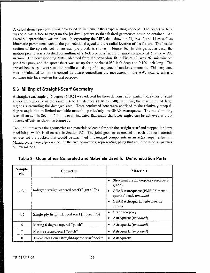
Table 2 summarizes the geometries and materials selected for both the straight-scarf and stepped-lap joint machining, which is discussed in Section 5.7. The joint geometries created in each of two materials represented the pockets that would be machined in damaged components in an actual repair situation. Mating parts were also created for the two geometries, representing plugs that could be used as patches of new material.
Table 2. Geometries Generated and Materials Used for Demonstration Parts
Sample No.
Geometry Materials
1,2,3 6-degree straight-tapered scarf (Figure 17a)
• Structural graphite-epoxy (aerospace grade)
• GEAE Astroquartz (PMR-15 matrix, quartz fibers), uncoated
• GEAE Astroquartz, rain erosion coated
4,5 Single-ply-height stepped scarf (Figure 17b) • Graphite-epoxy
• Astroquartz {uncoated)
6 Mating 6-degree tapered "patch" • Astroquartz {uncoated)
7 Mating stepped-scarf "patch" • Astroquartz {uncoated)
8 Two-dimensional straight-tapered scarf pocket • Astroquartz
TR-716/06-96 22

3 S c o Ü "0
I c o Ü k.
to a> ft s c p O
CD
N O 5
o 0 CD
CD TJ
t= CO o (/)
"55 ■o o
cr
w c o o CD E o
a) 0
CD Q. .^ O 5
CN II CD O 0 Q_
J£ O 5
o 0)
"?5
CO o tr
U o E ^ o o fe "o ^ CD C CD O Q.
E
o:
c in TJ CD 0)
3 O CD
CT n C a> ra - o *
e ^ *•«* o a
V) CD V)
E s 5
in r E cn a, TJ
»•- o o o ««M
L- c II 0) CD c
O) CD
o CO o
3 o
D TJ
TJ CD CD a.
CO
o E
CD CD
CD
CD
CD E > CD O CD
E -y CD a)
CO o
CD Q. 'S C E o
'S §" & TJ
O E
_0
CD
a m CM T- CD o CD T-
TJ CJ) CO h- ^j csi in
CD
c o o o CO CM i-
CD o o o
CD E CD CD
o
II CD &
■o > o <"
0) CD N Q.
CD O
CD ro
CD 3 2 Ä
CO TJ CD
C C iS E co XJ
XI —
N ■£ X>
CO o
II II
J T3 3
II II II E-t-3
II II — f<C
a) ro
> o E CD a:
5 ii
E s
CD a.
co Ü " 2 CO Q.
to to CD CD a a
O CD
CO £■ CD CD CO X) CO ~ 5 1= Q. 0 cJ E ._ 0
CO Ü
I- Q _i
CD E O) CD CO
£: CD "fc 2 * ro !=; 2 CO c Q.
■s-s's
co t co c 'S c
jD O _0
s! E JE«) CO 3 CO
II || II II II II II II
c CD E co CD t
CO o
c CD
CD CD CD 2 E CD
S o
CO £; CO
Q) CD
g I co E 0 >
t O) CO T- o CM m o CD i-
ons TJ" CD co cq CM CM
II II II II II II
c= -i z co E ^
o o
a. CO > Hi J .E •a .E i .fc .;=
vg ID CO LO *- O O S S Sm B O S P ö <N <=> -
"55
tr s a. o >. X a. 0 • •
3 o . "* TJ a
CD a. . w CO co 3
■c \=, T> O :r! CD
CD Q
°r D X
M- II
Q. 21
X CD CD 3 "2 ro .E > TJ T3
CD CD
'iö 'cö CD CD D Q
-rf ™ TJ O - CD
ro D b r
CD II Ea: 0 g
out o o .2
TJ ' 9>
■a g> _ 'cö 'iö
0
(U 0)
JZ tn
■u re 0) Q. X
o S) Q. c LU — (1) 1»- ■•-> o L. x: a. a.
■ ra c L.
o ü o C
S o -3 O)
1 < >«- t O re c o
o V)
*J a u a CD i_
w CO o
o Q TJ to re a re I i_
U) iZ.
TR-716/06-96 23
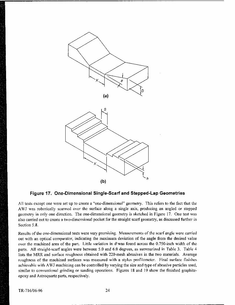
Figure 17. One-Dimensional Single-Scarf and Stepped-Lap Geometries
All tests except one were set up to create a "one-dimensional" geometry. This refers to the fact that the AWJ was robotically scanned over the surface along a single axis, producing an angled or stepped geometry in only one direction. The one-dimensional geometry is sketched in Figure 17. One test was also carried out to create a two-dimensional pocket for the straight scarf geometry, as discussed further in Section 5.8.
Results of the one-dimensional tests were very promising. Measurements of the scarf angle were carried out with an optical comparator, indicating the maximum deviation of the angle from the desired value over the machined area of the part. Little variation in 6 was found across the 0.750-inch width of the parts. All straight-scarf angles were between 5.0 and 6.0 degrees, as summarized in Table 3. Table 4 lists the MRR and surface roughness obtained with 220-mesh abrasives in the two materials. Average roughness of the machined surfaces was measured with a stylus profilometer. Final surface finishes achievable with AWJ machining can be controlled by varying the size and type of abrasive particles used, similar to conventional grinding or sanding operations. Figures 18 and 19 show the finished graphite- epoxy and Astroquartz parts, respectively.
TR-716/06-96 24

Table 3. Scarf Angles and Pocket Dimensions Obtained in AWJ Controlled Milling Demonstration Tests
Desired Actual
Scarf angle 6.0° 5.0-6.0°
Pocket depths 0.040 in.
0.080 in.
0.033 - 0.040 in.
0.078 - 0.080 in.
Pocket widths
0.100 in.
0.250 in.
2.000 in.
0.107 in.
0.229 - 0.250 in.
2.083 in.
Table 4. Removal Rate and Typical Average Roughness for AWJ-Machined Composite Surfaces
Material Material Removal
Rate (p.in./pass) Ra (pin.)
Graphite-epoxy 260 150-180
GEAE Astroquartz 450 250-300
6° Scarf Flat Bottom
Figure 18. AWJ-Milled Single-Scarf Geometry in Graphite-Epoxy
TR-716/06-96 25

Mating Patch
ÜksÜai
Flat Bottom
Figure 19. AWJ-Milled Single-Scarf Geometry in GEAE Astroquartz
Figure 20 shows another 6-degree scarf and wide pocket machined in a coated Astroquartz sample. The Viton rain-erosion coating was found to erode uniformly during the AWJ machining process. The coating was removed at a slower rate than the underlying composite, but did not crack, spall, or peel as the jet was applied. After the coating was worn through, the same jet scanning profile was used to create angled surfaces in the substrate material, leaving a sharp, straight coating edge with no coating/substrate debonding.
Given the uncertainties in material removal rates estimated from Figures 13 and 14, these results are excellent. They clearly demonstrate the feasibility of controlled AWJ contour milling for repair of composite components. More specifically, the relatively high accuracy of the scarf angles achieved here verifies that nozzle motion profiling can be used to predict the machining pattern required for a given geometry. Once MRRs are accurately known for a particular workpiece material, this approach can be used to automatically machine a near-final geometry. Mapping of the near-net machined geometry can then be carried out and the detailed near-net geometry data used as input for high-accuracy AWJ finishing work.
TR-716/06-96 26

Viton Rain-Erosion Coating
L-Ö
AWJ-Machined Section
-* ► \< M ■*- Coated Surface Scarf Pocket
—fr I ■<] ffi I -^—
Scarf Coated Surface
Figure 20. Removal of Rain Erosion Coating and Scarf Milling in GEAE Astroquartz
5.7 Milling of Stepped-Lap Geometry
For this task, initial tests investigated the feasibility of obtaining the stepped geometry without using masking techniques, simply by controlling the AWJ nozzle motion as discussed in Section 5.5. However, jet spreading effects, which in the single-scarf case created desirable smooth contours, tended to create undesirable rounding of the steps. We therefore found it necessary to develop suitable masking tech- niques, as shown in Figure 21. Thin sheet metal masks were temporarily laid over the steps bordering the area being worked on to protect the step edges. While tedious to apply, this technique successfully produced sharp, clean step edges.
As with the straight scarf, the geometry was milled in both the graphite-epoxy and Astroquartz materials, as shown in Figure 22. A mating part was also machined from Astroquartz, as shown in Figure 23. In the latter case, each side of the part was masked and milled separately to avoid passing the AWJ over the center section.
TR-716/06-96 27

NOZZLE
REMOVABLE MASK
POCKET MACHINED TO DEPTH OF ONE STEP
ORIGINAL SURFACE
RANGE OF NOZZLE MOTION
STAGE #1
WORKPIECE
MASKS
SURFACE AFTER STAGE #2
PART MOTION
SURFACE AFTER STAGE #1
STAGE #2
STAGE #3
PART MOTION
FINAL SHAPE
Figure 21. Masking Scheme for AWJ Machining of the Stepped-Lap Geometry
GEAE Astroquartz
Graphite-Epoxy
Figure 22. AWJ-Milled Stepped-Lap Geometry
TR-716/06-96 28

Mating Patch
Figure 23. AWJ-Machined Stepped-Lap Pocket and Patch in GEAE Astroquartz
The objective here was to create uniform steps with a height equal to the thickness of a single ply. Dimensional accuracy achieved in the demonstration parts was excellent, as summarized in Table 5. Step length was determined by the dimensions and placement of the masks. As long as a sharp inside corner could be achieved in a given step, it was not difficult to precisely place the mask over it while milling the adjacent, next-deepest step. So the high accuracy shown for the step lengths in Table 5 is not unexpected. Step heights were obtained by measuring the part thickness with a micrometer at two points on each step of each part. Measured step heights were uniform to within the thickness tolerances of the original, unmachined materials. The accuracy in the step height is a direct result of the low MRRs achieved with the process (see Table 4), as well as the uniformity of the material removal over large areas.
Table 5. Step Dimensions Obtained in AWJ Machining Demonstration Tests
Sample No. Material and Geometry
Step Height (in.) Step Length, s (in.)
Desired Actual Desired Actual
4 Graphite-epoxy pocket 0.007 0.007 0.250 0.247
5 Astroquartz pocket 0.008 0.008 0.250 0.253
7 Astroquartz patch 0.008 0.008-0.009 0.250 0.253-0.254
TR-716/06-96 29

5.8 Two-Dimensional Pocket Machining
5.8.1 AWJ Machining
A preliminary attempt was made to extend the results of the one-dimensional straight-scarf milling to create a two-dimensional square pocket. In this test, the machining was carried out in two successive steps. First, an appropriately shaped mask was temporarily bonded to the surface and the AWJ scanned in one dimension. When the desired wall geometry was created in that direction, the mask was removed, the part was rotated 90 degrees, and a second mask was applied to avoid damage to the already-machined surface. The jet was then scanned in the same pattern to create tapered walls in the orthogonal direction. This created a two-dimensional pocket with a flat bottom, tapered walls, and mitered corners, as sketched in Figure 24. Figure 25 shows the finished part as well as the two masks.
Adequate control of the wall taper was achieved in both directions. However, interactions between the jet and the second mask created undesirable grooves along the mask edges. The location of these grooves along the edges of the pocket is sketched in bold lines in Figure 24. The grooves, visible in Figure 25, ranged in depth from approximately 0.005 to 0.030 inch. This "undercutting" around mask edges has been observed in other AWJ milling processes, and its severity has been found to be a complex function of the AWJ process parameters, mask thickness and hardness, and part geometry. Optimization of these variables is needed to minimize this effect, which could otherwise decrease the strength of the underlying, undamaged composite in a repair.
Figure 24. Two-Dimensional Straight Scarf Geometry
V First Mask
V Second Mask
Figure 25. AWJ-Machined Two-Dimensional Scarf Pocket
TR-716/06-96 30

5.8.2 Microblaster Machining
Preliminary tests were also carried out to evaluate the performance of a dry abrasive "microblaster." This commercially available device, developed for drilling cavities in teeth, uses low-pressure air to accelerate fine abrasive particles in hand-held nozzles. Common uses include surface cleaning, etching, and deburring. Some of the characteristics distinguishing AWJ and microblaster machining are sum- marized in Table 6.
Table 6. Comparison of AWJ and Microblaster Machining
AWJ Microblaster
Process type: Wet abrasive Dry abrasive
Cutting power: High Low
Abrading power: Variable: Moderate to high Low to moderate
Required nozzle/workpiece relative translation speed:
High (900-1200 in./min) Low (10-15 in./min)
The advantages of the AWJ include the high cutting power and wide range of abrading power available for other potential repair applications (e.g., cutting away damaged areas, cutting or machining harder materials such as hot-section blades and vanes, etc.). Disadvantages are the potential for water pene- tration between composite plies (though none was detected in this study) and the need to move the nozzle rapidly over the workpiece to maintain process control and avoid workpiece damage.
Microblaster tests were conducted with the same 220-mesh garnet abrasives used in the AWJ tests. The microblaster nozzle was mounted to a three-axis robotic manipulator in WTI's waterjet machining laboratory and scanned at low speed over the stationary workpiece. Minimal effort was expended to optimize microblaster process parameters. Using a rough best-case parameter set, we attempted to create several shallow two-dimensional stepped-scarf pockets in the Astroquartz material. The technique consisted of scanning the nozzle in successively smaller checkerboard patterns, with more jet dwell time in the center of the machined area. In contrast to the AWJ technique, no masking of the material was required for this approach, because the jet never passed over areas where material removal was forbidden. The results of several tests are shown in Figure 26. Although an approximate stepped-scarf configuration was obtained, the surface achieved would be too rough to accept a layup of prepreg plies.
These initial results were not as favorable as those obtained with the AWJ. However, the microblaster technique may still be worthy of pursuit, since it promises several desirable characteristics including little or no masking requirements, the elimination of water, lower surface speed, and a lightweight, compact
nozzle.
TR-716/06-96 31

Figure 26. Microblaster-Machined Two-Dimensional Stepped-Lap Pocket
TR-716/06-96 32

6. CONCLUSIONS AND RECOMMENDATIONS
The following results were obtained in the Phase I work:
1. Straight-tapered and stepped-scarf geometries suitable for repair preparations were AWJ machined in two aerospace composite materials.
2. Results of one-dimensional tests were very promising, with excellent control of part geometry and surface finish.
3. Limited attempts at machining two-dimensional pockets identified issues needing further work, including undercutting effects at the edge of masks.
4. Preliminary machining tests were carried out with a dry-abrasive "microblaster." Process and per- formance tradeoffs between the AWJ and microblaster techniques were identified. Better control of the machining process was obtained with the AWJ in this study, but the microblaster offers several attractive features, suggesting that further work developing this process may be warranted.
Based on these results, the following conclusions and recommendations can be drawn regarding AWJ- based machining processes for composite repair:
• The precision scarfing process is technically feasible. Excellent control of workpiece geometry and surface finish have been demonstrated.
• The technology appears to be cost effective, due to the relatively high speed and the absence of hard tool/workpiece contact. This eliminates the need for high-accuracy manipulation of the cutting tool relative to the surface of the part.
• No damage is imparted to the workpiece. Delamination, fiber breakage or pullout, or water inclusion were not observed.
• The technique is flexible, allowing a range of materials and geometries to be machined without sig- nificant tooling or process changes.
• The process can be automated with the addition of surface mapping technology and appropriate feed- back algorithms. This offers the potential for low-skilled operation and low production costs.
• The tradeoffs between AWJ and dry-abrasivejet (e.g., microblaster) techniques should be explored further. The compact and lightweight microblaster nozzle is attractive for high-speed motion within a slow-moving manipulator head scanning over the workpiece surface. The AWJ, on the other hand, is more versatile and is capable of high-speed cutting and drilling of a wide variety of materials, as well as shaping and milling.
TR-716/06-96 33

REFERENCES
Halle, J. E., Burger, E. D., and Dundas, R. E. (1977) NASA CR-135122, PWA-5487, Pratt and Whitney Aircraft.
Hashish, M. (1984) "A Modeling Study of Metal Cutting with Abrasive-Waterjets," Journal of Engi- neering Materials and Technology, ASME Trans., Vol. 106, No. 1, pp. 88-100.
Hashish, M. (1989) "Machining of Advanced Composites with Abrasive-Waterjets," Manufacturing Review, Vol. 2, No. 2, pp. 142-150.
Hashish, M., Miles, P., Lilley, R., Bothell, D., Hake, J., and Steele, D. (1994) "Development of Abrasive- Waterjet Milling Center," Final report prepared for DET 10, SMC/SDC, under Contract No. F04704- 91-C-0059, BMO-TR-94-36, October.
IHPTET (1994) "IHPTET Technology Teams in Action," Summary of program progress at the 1994 Turbine Engine Technology Symposium, Oct. 3-5, Dayton, OH.
Kandebo, S. W. (1994) "U.S., Europe Race for MMC Payoff," Aviation Week & Space Technology, Aug. 22, pp. 20-22.
May, G., and Hashish, M (1996) "Flexible Automated Finishing of Precision Optics," Final report prepared for U.S. Army Picatinny Arsenal under Contract No. DAAE30-95-C-0090, WTI Technical Report No. 714, May.
Serafini, T. (1987) "High Temperature Applications," in Engineered Materials Handbook, Vol. J, Com- posites, ASM International Handbook Committee, pp. 810-815.
TR-716/06-96 34

REPORT DOCUMENTATION PAGE Form Approved
OMB No. 0704-0188
Public reporting burden for this collection of information is estimated to average 1 hour per response, including the time for reviewing instructions, searching existing data sources, gathering and maintaining the data needed, and completing and reviewing the collection of information. Send comments regarding this burden estimate or any other aspect of this collection of information, including suggestions for reducing this burden, to Washington Headquarters Services, Directorate for information Operations and Reports, 1215 Jefferson Davis Highway, Suite 1204, Arlington, VA 22202-4302, and to the Office of Management and Budget, Paperwork Reduction Project (0704-0188), Washington, DC 20503.
1. AGENCY USE ONLY (leave blank) REPORT DATE
June 1996 REPORT TYPE AND DATES COVERED
Final - 25 Sept 1995 - 28 March 1996
4. TITLE AND SUBTITLE
Waterjet Techniques for Composite Material Jet Engine Component Repair
6. AUTHOR(S)
C. Dunsky, P. Tacheron, and M. Hashish
5. FUNDING NUMBERS
N000421-95-C-1141
7. PERFORMING ORGANIZATION NAME(S) AND ADDRESS(ES)
QUEST Integrated, Inc. 21414 68th Ave. S. Kent, WA 98032
8, PERFORMING ORGANIZATION REPORT NUMBER
Technical Report No. 716
9. SPONSORING/MONITORING AGENCY NAME(S) AND ADDRESS(ES)
Naval Air Warfare Center, Aircraft Division Bldg588, MS 32 Patuxent River, MD 20670-5304
10. SPONSORING/MONITORING AGENCY REPORT NUMBER
11. SUPPLEMENTARY NOTES
12a. DISTRIBUTION/AVAILABILITY STATEMENT
Approved for public release; SBIR report, distribution unlimited.
12b. DISTRIBUTION CODE
13. ABSTRACT (Maximum 200 words)
This Phase I SBIR project addressed the feasibility of using abrasive-waterjet (AWJ) machining technology for the repair of jet engine components fabricated from composites. AWJ milling techniques were adapted to remove pre- cise amounts of the composite materials without damage such as delamination or fiber pullout. The approach can be used for the removal of damaged sections of composite components and high-precision preparation of the affected area before bonding or fastening of patching material.
Machining of two common composite repair geometries was demonstrated, including low-angle straight-scarf joints and stepped-lap joints. For the former case, the objective was to produce two 6-degree walls with a flat- bottomed pocket between them. In the latter, the objective was to machine a series of steps with heights equal to the ply thickness, typically 0.007-0.008 inch. Demonstration straight-scarf parts were produced in two materials with the desired pocket lengths and depths and wall angles of 5.0 to 6.0 degrees. Stepped-lap parts were also produced in the two materials with step heights deviating from the ply thickness by no more than 0.001 inch. The demonstrated ability to predict and control the material removal pattern indicates that this technique can find wide application in precision shaping of aerospace composites.
14. SUBJECT TERMS
Abrasive-Waterjet, Blades, Composite Repair, Foreign-Object Damage, t Jet Engine, Vanes, Waterjet
15. NUMBER OF PAGES 35
16. PRICE CODE
17. SECURITY CLASSIFICATION OF REPORT
Unclassified
18. SECURITY CLASSIFICATION OF THIS PAGE
Unclassified
19. SECURITY CLASSIFICATION OF ABSTRACT
Unclassified
20. LIMITATION OF ABSTRACT
Unlimited
Standard Form 298