waterless fracturing technology - society of petroleum...
TRANSCRIPT
WaterLess Fracturing Technology
SPE October 12, 2010 Tyler, TX
Frac Water Usage Issues
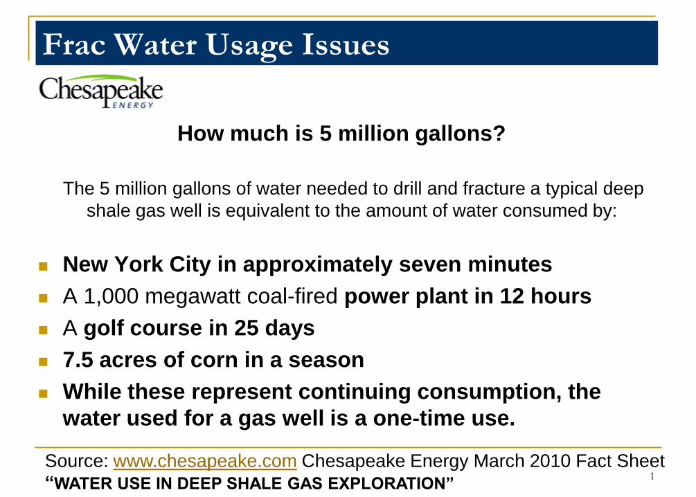
How much is 5 million gallons?
The 5 million gallons of water needed to drill and fracture a typical deep
shale gas well is equivalent to the amount of water consumed by:
New York City in approximately seven minutes
A 1,000 megawatt coal-fired power plant in 12 hours
A golf course in 25 days
7.5 acres of corn in a season
While these represent continuing consumption, the
water used for a gas well is a one‐time use.
1Source: www.chesapeake.com Chesapeake Energy March 2010 Fact Sheet
“WATER USE IN DEEP SHALE GAS EXPLORATION”
Frac Water Usage Issues
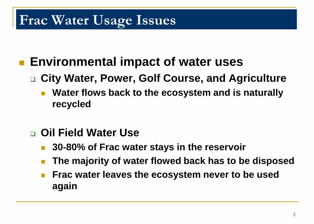
Environmental impact of water uses
City Water, Power, Golf Course, and Agriculture
Water flows back to the ecosystem and is naturally
recycled
Oil Field Water Use
30-80% of Frac water stays in the reservoir
The majority of water flowed back has to be disposed
Frac water leaves the ecosystem never to be used
again
2
Why Waterless is Important to Society
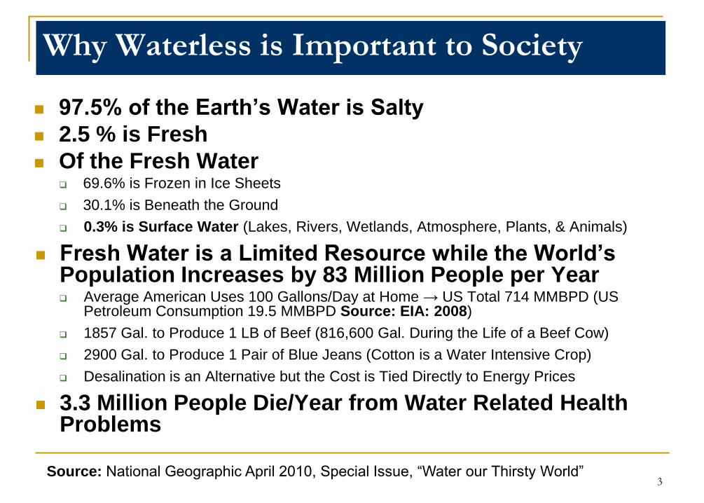
97.5% of the Earth‟s Water is Salty
2.5 % is Fresh
Of the Fresh Water 69.6% is Frozen in Ice Sheets
30.1% is Beneath the Ground
0.3% is Surface Water (Lakes, Rivers, Wetlands, Atmosphere, Plants, & Animals)
Fresh Water is a Limited Resource while the World‟s Population Increases by 83 Million People per Year Average American Uses 100 Gallons/Day at Home → US Total 714 MMBPD (US
Petroleum Consumption 19.5 MMBPD Source: EIA: 2008)
1857 Gal. to Produce 1 LB of Beef (816,600 Gal. During the Life of a Beef Cow)
2900 Gal. to Produce 1 Pair of Blue Jeans (Cotton is a Water Intensive Crop)
Desalination is an Alternative but the Cost is Tied Directly to Energy Prices
3.3 Million People Die/Year from Water Related Health Problems
3Source: National Geographic April 2010, Special Issue, “Water our Thirsty World”
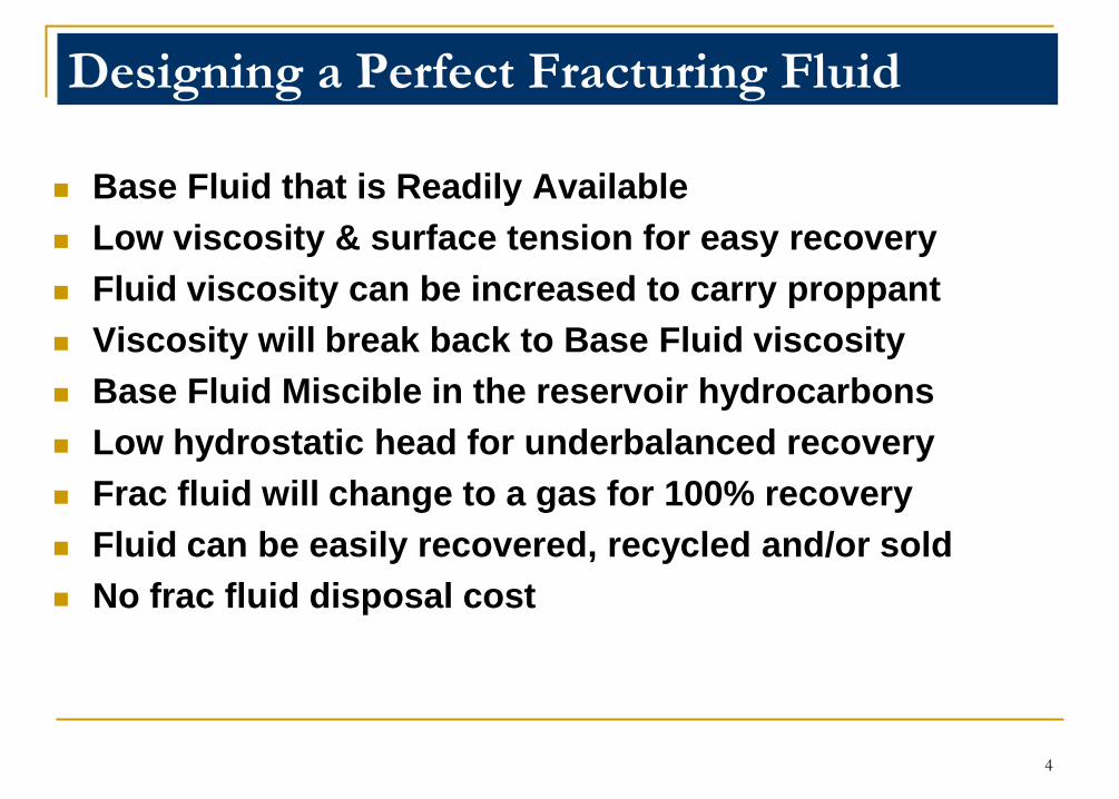
Designing a Perfect Fracturing Fluid
Base Fluid that is Readily Available
Low viscosity & surface tension for easy recovery
Fluid viscosity can be increased to carry proppant
Viscosity will break back to Base Fluid viscosity
Base Fluid Miscible in the reservoir hydrocarbons
Low hydrostatic head for underbalanced recovery
Frac fluid will change to a gas for 100% recovery
Fluid can be easily recovered, recycled and/or sold
No frac fluid disposal cost
4
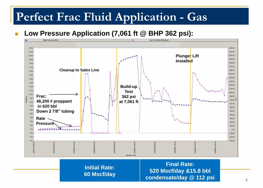
Perfect Frac Fluid Application - Gas
Low Pressure Application (7,061 ft @ BHP 362 psi):
Initial Rate:
60 Mscf/day
Final Rate:
520 Mscf/day &15.8 bbl
condensate/day @ 112 psi
Frac:
46,200 # proppant
in 620 bbl
Down 2 7/8” tubing
Build-up
Test
362 psi
at 7,061 ft
Plunger Lift
Installed
Rate
Pressure
90 days
Cleanup to Sales Line
5
0
50
100
150
200
250
300
0 50000 100000 150000 200000 250000 300000 350000 400000
Ra
te (
BO
E/O
p D
ay)
Cumulative Production (BOE)
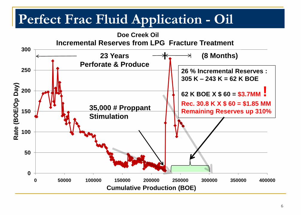
Incremental Reserves from LPG Fracture Treatment
26 % Incremental Reserves :
305 K – 243 K = 62 K BOE
62 K BOE X $ 60 = $3.7MM !Rec. 30.8 K X $ 60 = $1.85 MM
Remaining Reserves up 310%
Perfect Frac Fluid Application - Oil
23 Years
Perforate & Produce
(8 Months)
35,000 # Proppant
Stimulation
Doe Creek Oil
6
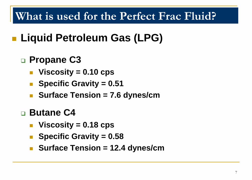
What is used for the Perfect Frac Fluid?
Liquid Petroleum Gas (LPG)
Propane C3
Viscosity = 0.10 cps
Specific Gravity = 0.51
Surface Tension = 7.6 dynes/cm
Butane C4
Viscosity = 0.18 cps
Specific Gravity = 0.58
Surface Tension = 12.4 dynes/cm
7
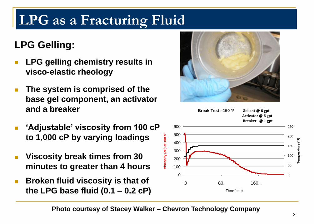
LPG as a Fracturing Fluid
LPG Gelling:
LPG gelling chemistry results in
visco-elastic rheology
The system is comprised of the
base gel component, an activator
and a breaker
„Adjustable‟ viscosity from 100 cP
to 1,000 cP by varying loadings
Viscosity break times from 30
minutes to greater than 4 hours
Broken fluid viscosity is that of
the LPG base fluid (0.1 – 0.2 cP)
0
50
100
150
200
250
0
100
200
300
400
500
600
0 81 158
Tem
pe
ratu
re (
°F)
Vis
co
sit
y (
cP
) at
100 s
-1
Time (min)
Break Test - 150 °F Gellant @ 6 gptActivator @ 6 gptBreaker @ 1 gpt
0 80 160
8Photo courtesy of Stacey Walker – Chevron Technology Company
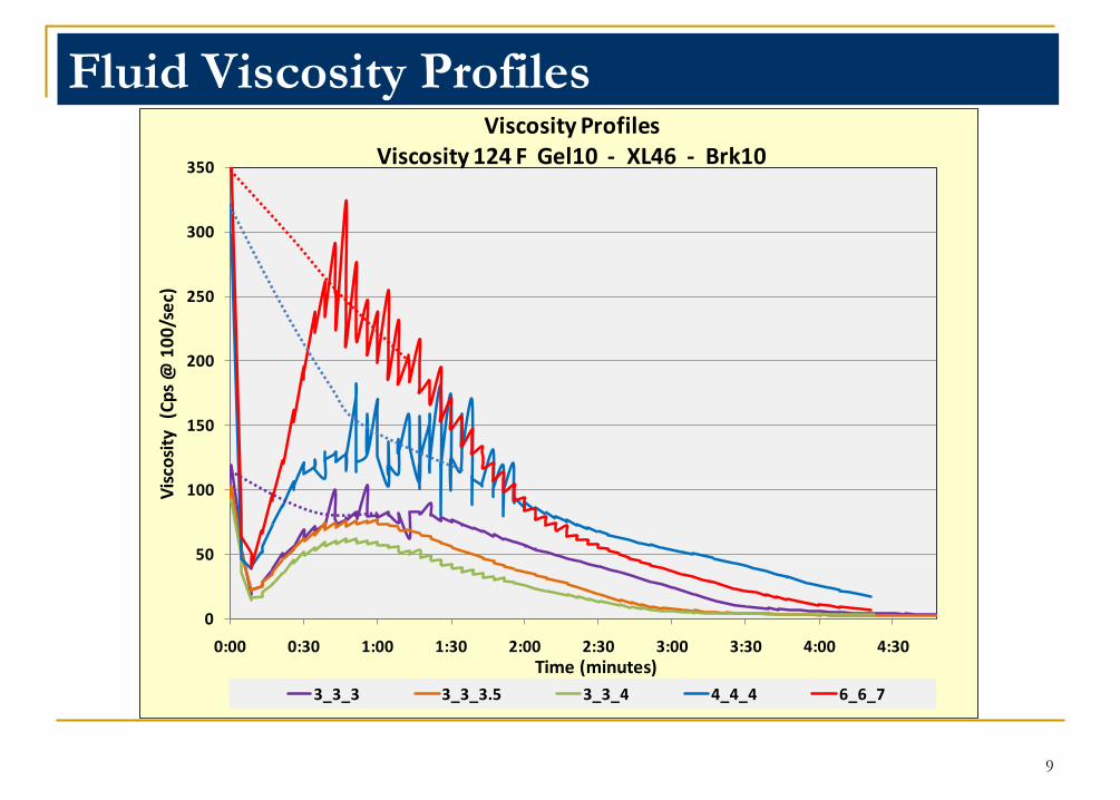
Fluid Viscosity Profiles
9
0
50
100
150
200
250
300
350
0:00 0:30 1:00 1:30 2:00 2:30 3:00 3:30 4:00 4:30
Vis
cosi
ty
(Cp
s @
10
0/s
ec)
Time (minutes)
Viscosity ProfilesViscosity 124 F Gel10 - XL46 - Brk10
3_3_3 3_3_3.5 3_3_4 4_4_4 6_6_7
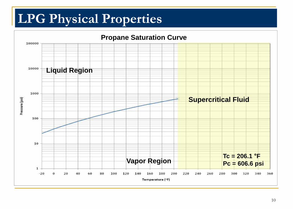
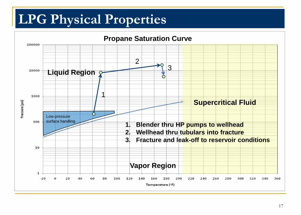
LPG Physical Properties
Propane Saturation Curve
Liquid Region
Vapor RegionTc = 206.1 °F
Pc = 606.6 psi
10
Supercritical Fluid
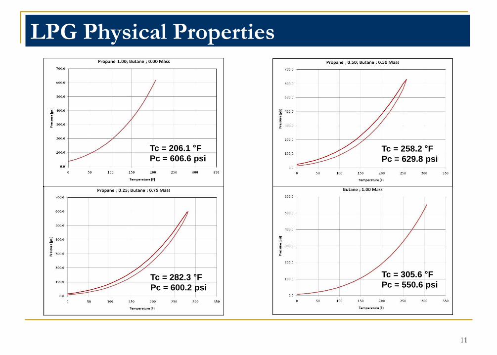
Tc = 206.1 °F
Pc = 606.6 psi
Tc = 282.3 °F
Pc = 600.2 psi
Tc = 305.6 °F
Pc = 550.6 psi
Tc = 258.2 °F
Pc = 629.8 psi
LPG Physical Properties
11
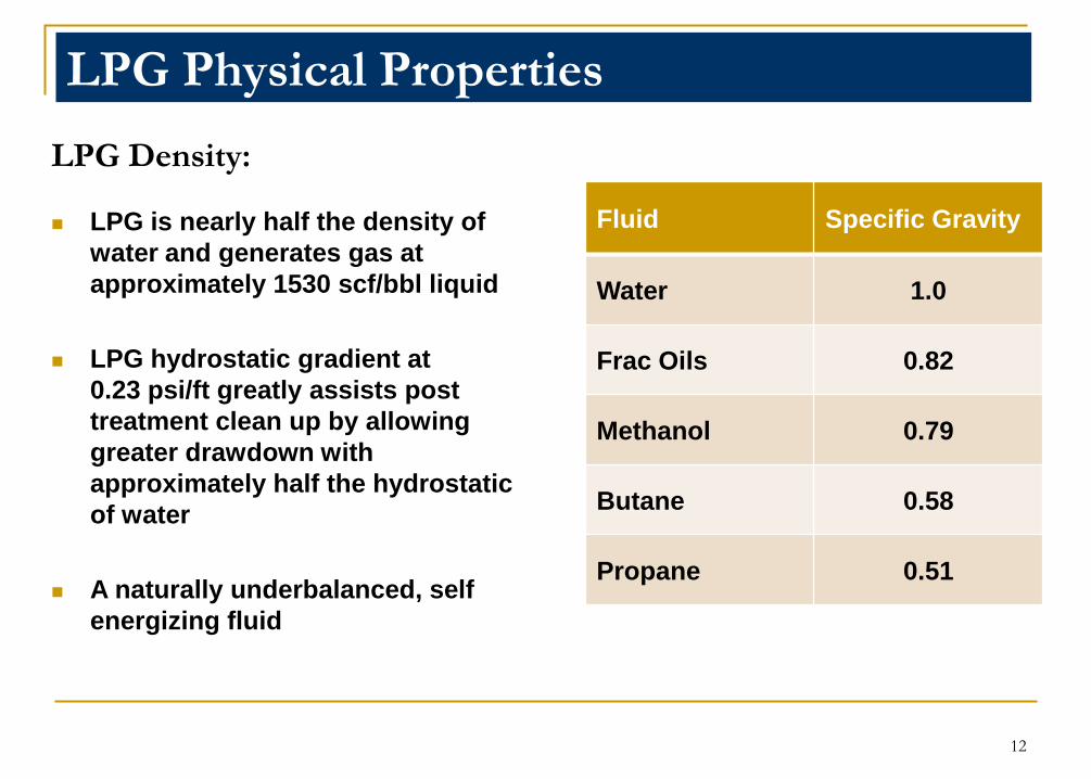
LPG Density:
LPG is nearly half the density of
water and generates gas at
approximately 1530 scf/bbl liquid
LPG hydrostatic gradient at
0.23 psi/ft greatly assists post
treatment clean up by allowing
greater drawdown with
approximately half the hydrostatic
of water
A naturally underbalanced, self
energizing fluid
Fluid Specific Gravity
Water 1.0
Frac Oils 0.82
Methanol 0.79
Butane 0.58
Propane 0.51
LPG Physical Properties
12
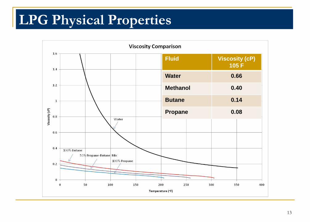
LPG Physical Properties
Fluid Viscosity (cP)
105 F
Water 0.66
Methanol 0.40
Butane 0.14
Propane 0.08
13

LPG Physical Properties
Fluid
Surface
Tension
dyn/cm at
70F
Water 72.8
Frac Oils 21.8
Methanol 22.7
Butane 12.4
Propane 7.6
14
LPG Physical Properties
0.1
1
10
100
1000
10000
100000
0.001 0.01 0.1 1
Cap
illar
y Th
resh
old
Pre
ssu
re (p
si)
Pore Diameter (microns)
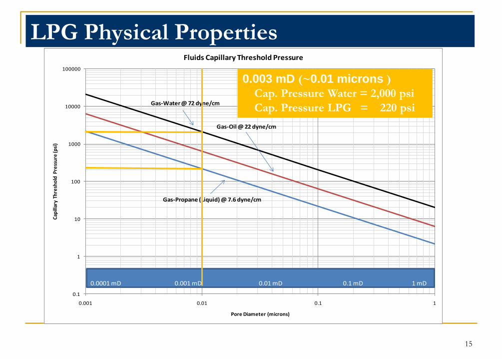
Fluids Capillary Threshold Pressure
0.0001 mD 0.001 mD 0.01 mD 0.1 mD 1 mD
Gas-Oil @ 22 dyne/cm
Gas-Water @ 72 dyne/cm
Gas-Propane (Liquid) @ 7.6 dyne/cm
0.003 mD (~0.01 microns )
Cap. Pressure Water = 2,000 psi
Cap. Pressure LPG = 220 psi
15
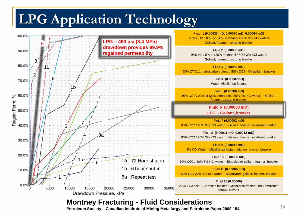
Fluid 1 (0.00033 mD, 0.00070 mD, 0.00054 mD)
60% CO2 / 40% of (20% methanol / 80% 3% KCl water)
Gellant, foamer, oxidizing breaker
Fluid 2 (0.00050 mD)
95% N2 / 5% of (20% methanol / 80% 3% KCl water)
Gellant, foamer, oxidizing breaker
Fluid 3 (0.00080 mD)
50% C7-C11 hydrocarbon blend / 50% CO2 - Oil gellant, breaker
Fluid 4 (0.00087mD)
Water Micellar surfactant
Fluid 5 (0.00086 mD)
80% CO2 / 20% of (20% methanol / 80% 3% KCl water) - Gellant,
foamer, oxidizing breaker
Fluid 6 (0.00053 mD)
LPG - Gellant, breaker
Fluid 7 (0.00002 mD)
60% CO2 / 40% 3% KCl water - Gellant, foamer, oxidizing breaker
Fluid 8 (0.00011 mD, 0.00012 mD)
80% CO2 / 20% 3% KCl water - Gellant, foamer, oxidizing breaker
Fluid 9 (0.00016 mD)
3% KCl Water - Micellar surfactant, friction reducer, breaker
Fluid 10 (0.00036 mD)
60% CO2 / 40% 3% KCl water - Biopolymer gellant, foamer, breaker
Fluid 11 (0.00006 mD)
80% N2 / 20% 3% KCl water - Biopolymer gellant, foamer, breaker
Fluid 12 (0.00066)
2.5% HCl acid - Corrosion inhibitor, Micellar surfactant, non-emulsifier,
mutual solvent
LPG Application Technology
1a
2
3
4
57
8
9
1011
12
1b
8a1
6
1a
1b
72 Hour shut-in
6 hour shut-in
Repeat test
8a
LPG – 493 psi (3.4 MPa)
drawdown provides 99.9%
regained permeability
Montney Fracturing - Fluid ConsiderationsPetroleum Society – Canadian Institute of Mining Metallurgy and Petroleum Paper 2009-154 16
Propane Saturation Curve
Liquid Region
Vapor Region
Supercritical Fluid
LPG Physical Properties
17
1. Blender thru HP pumps to wellhead
2. Wellhead thru tubulars into fracture
3. Fracture and leak-off to reservoir conditions
Low-pressure
surface handling
1
23
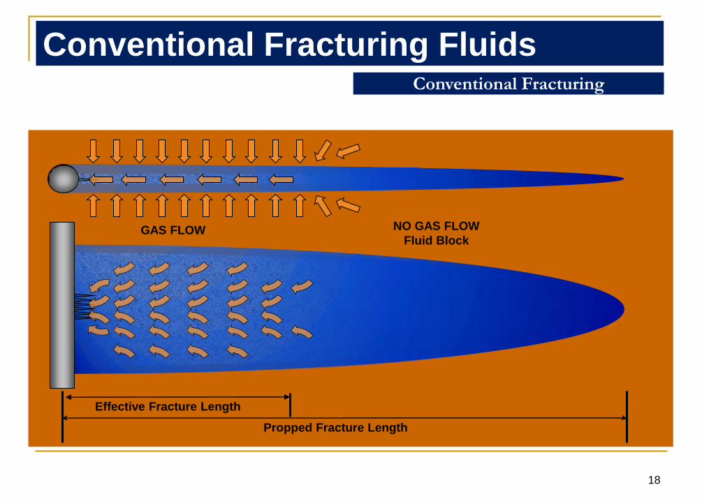
Effective Fracture Length
Propped Fracture Length
Conventional Fracturing
Conventional Fracturing Fluids
GAS FLOW NO GAS FLOW
Fluid Block
18
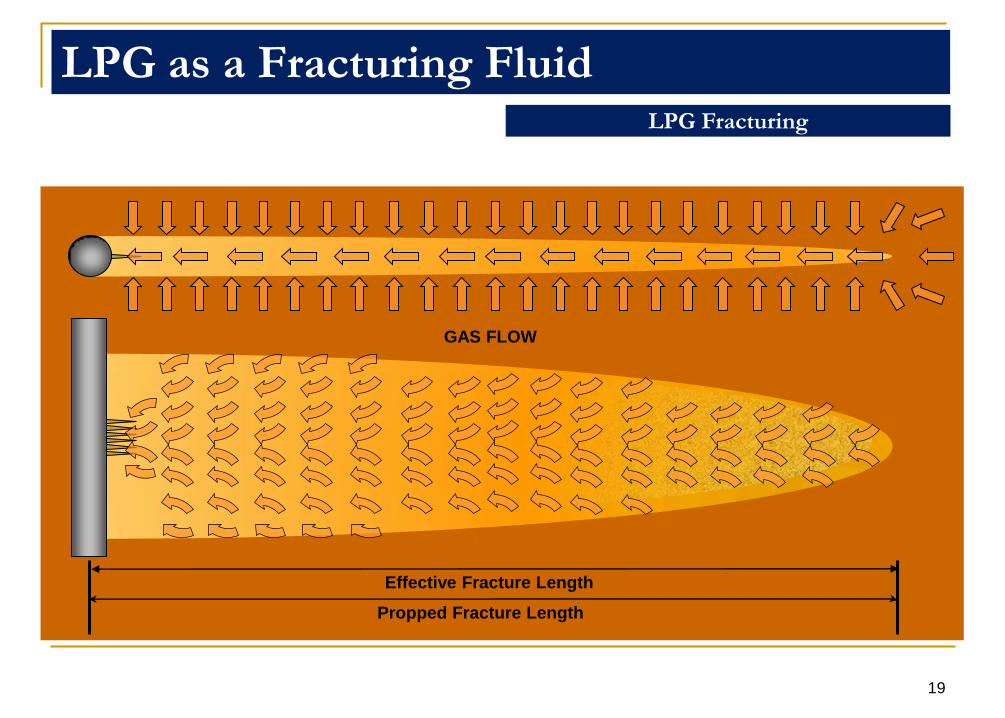
GAS FLOW
LPG Fracturing
LPG as a Fracturing Fluid
Effective Fracture Length
Propped Fracture Length
19
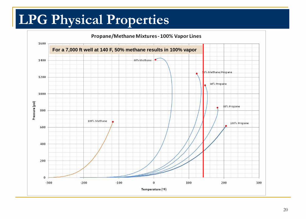
LPG Physical Properties
For a 7,000 ft well at 140 F, 50% methane results in 100% vapor
20
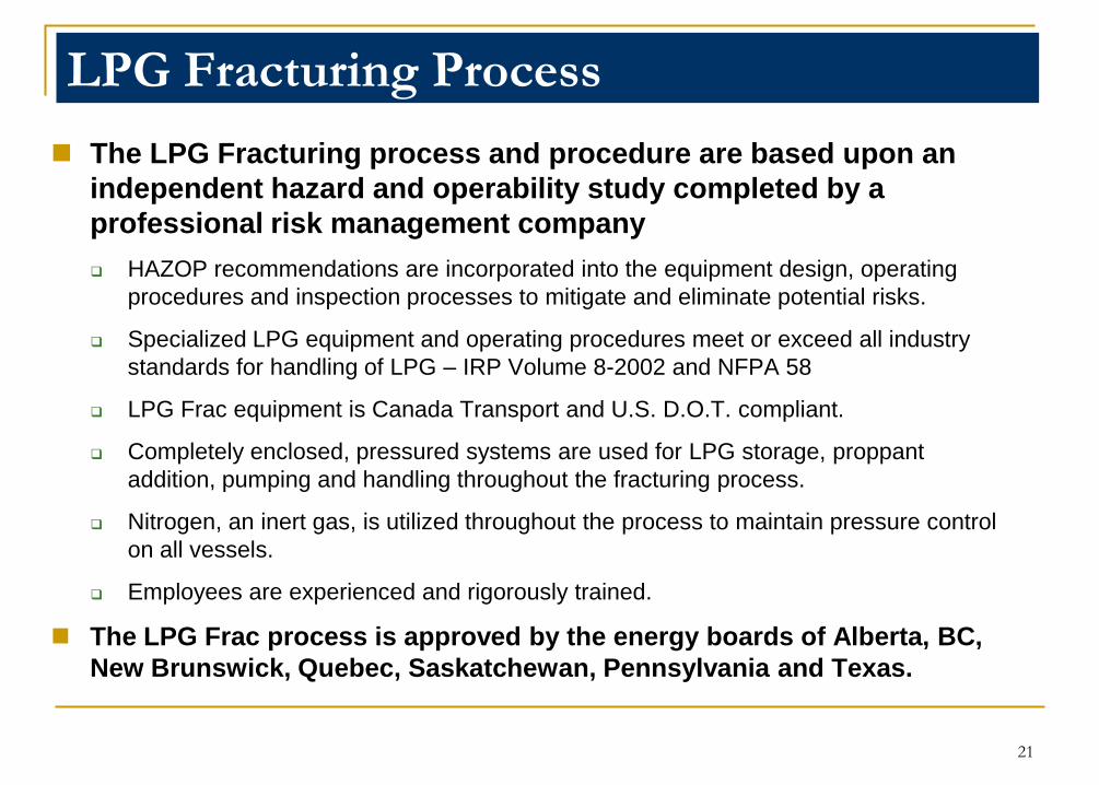
The LPG Fracturing process and procedure are based upon an
independent hazard and operability study completed by a
professional risk management company
HAZOP recommendations are incorporated into the equipment design, operating
procedures and inspection processes to mitigate and eliminate potential risks.
Specialized LPG equipment and operating procedures meet or exceed all industry
standards for handling of LPG – IRP Volume 8-2002 and NFPA 58
LPG Frac equipment is Canada Transport and U.S. D.O.T. compliant.
Completely enclosed, pressured systems are used for LPG storage, proppant
addition, pumping and handling throughout the fracturing process.
Nitrogen, an inert gas, is utilized throughout the process to maintain pressure control
on all vessels.
Employees are experienced and rigorously trained.
The LPG Frac process is approved by the energy boards of Alberta, BC,
New Brunswick, Quebec, Saskatchewan, Pennsylvania and Texas.
LPG Fracturing Process
21
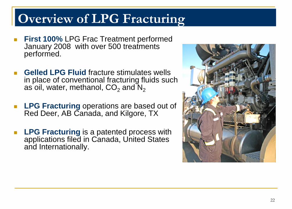
First 100% LPG Frac Treatment performed January 2008 with over 500 treatments performed.
Gelled LPG Fluid fracture stimulates wells in place of conventional fracturing fluids such as oil, water, methanol, CO2 and N2
LPG Fracturing operations are based out of Red Deer, AB Canada, and Kilgore, TX
LPG Fracturing is a patented process with applications filed in Canada, United States and Internationally.
Overview of LPG Fracturing
22
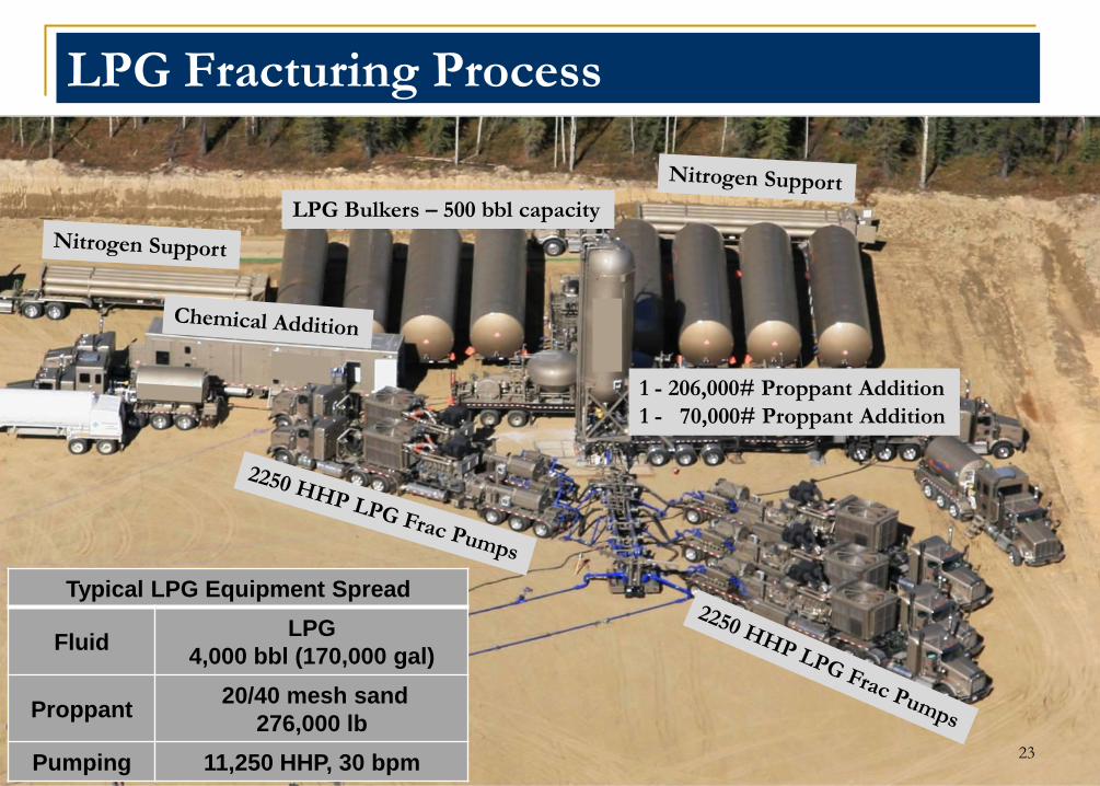
LPG Bulkers – 500 bbl capacity
1 - 206,000# Proppant Addition
1 - 70,000# Proppant Addition
Typical LPG Equipment Spread
Fluid LPG
4,000 bbl (170,000 gal)
Proppant20/40 mesh sand
276,000 lb
Pumping 11,250 HHP, 30 bpm
LPG Fracturing Process
23
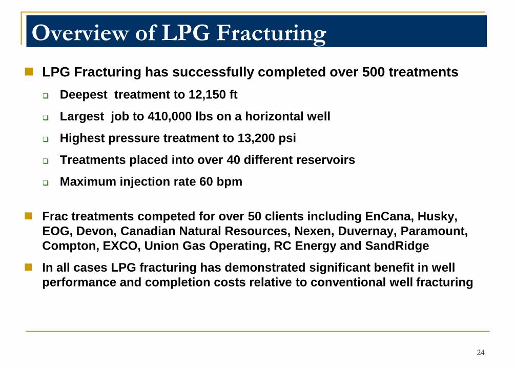
LPG Fracturing has successfully completed over 500 treatments
Deepest treatment to 12,150 ft
Largest job to 410,000 lbs on a horizontal well
Highest pressure treatment to 13,200 psi
Treatments placed into over 40 different reservoirs
Maximum injection rate 60 bpm
Frac treatments competed for over 50 clients including EnCana, Husky,
EOG, Devon, Canadian Natural Resources, Nexen, Duvernay, Paramount,
Compton, EXCO, Union Gas Operating, RC Energy and SandRidge
In all cases LPG fracturing has demonstrated significant benefit in well
performance and completion costs relative to conventional well fracturing
Overview of LPG Fracturing
24
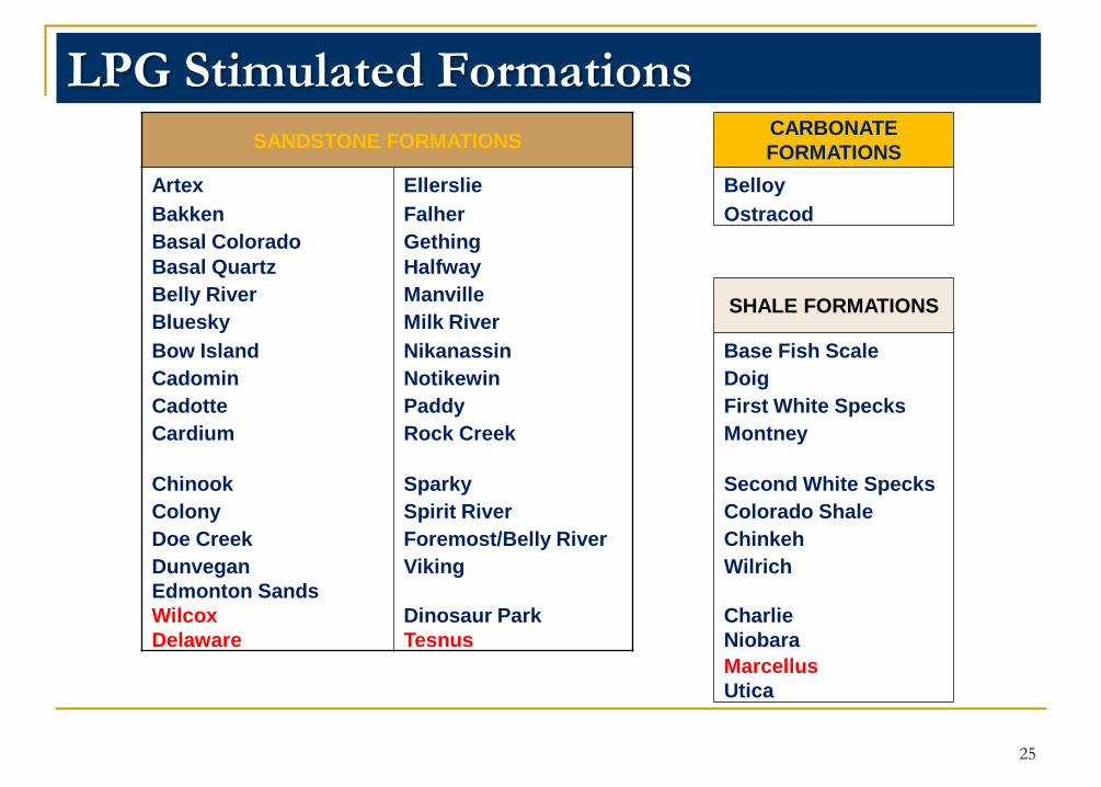
LPG Stimulated Formations
SANDSTONE FORMATIONSCARBONATE
FORMATIONS
Artex Ellerslie Belloy
Bakken Falher Ostracod
Basal Colorado Gething
Basal Quartz Halfway
Belly River ManvilleSHALE FORMATIONS
Bluesky Milk River
Bow Island Nikanassin Base Fish Scale
Cadomin Notikewin Doig
Cadotte Paddy First White Specks
Cardium Rock Creek Montney
Chinook Sparky Second White Specks
Colony Spirit River Colorado Shale
Doe Creek Foremost/Belly River Chinkeh
Dunvegan Viking Wilrich
Edmonton Sands
Wilcox
Delaware
Dinosaur Park
Tesnus
Charlie
Niobara
Marcellus
Utica
25
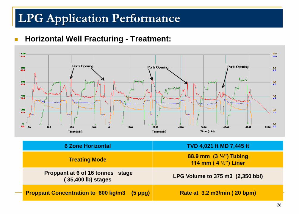
LPG Application Performance
Horizontal Well Fracturing - Treatment:
6 Zone Horizontal TVD 4,021 ft MD 7,445 ft
Treating Mode88.9 mm (3 ½”) Tubing
114 mm ( 4 ½”) Liner
Proppant at 6 of 16 tonnes stage
( 35,400 lb) stagesLPG Volume to 375 m3 (2,350 bbl)
Proppant Concentration to 600 kg/m3 (5 ppg) Rate at 3.2 m3/min ( 20 bpm)
26
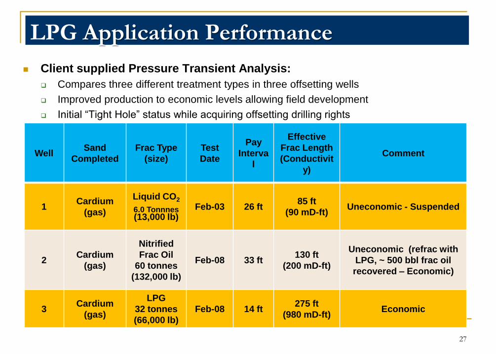
LPG Application Performance
Client supplied Pressure Transient Analysis:
Compares three different treatment types in three offsetting wells
Improved production to economic levels allowing field development
Initial “Tight Hole” status while acquiring offsetting drilling rights
WellSand
Completed
Frac Type
(size)
Test
Date
Pay
Interva
l
Effective
Frac Length
(Conductivit
y)
Comment
1Cardium
(gas)
Liquid CO2
6.0 Tonnnes(13,000 lb)
Feb-03 26 ft85 ft
(90 mD-ft)Uneconomic - Suspended
2Cardium
(gas)
Nitrified
Frac Oil
60 tonnes
(132,000 lb)
Feb-08 33 ft130 ft
(200 mD-ft)
Uneconomic (refrac with
LPG, ~ 500 bbl frac oil
recovered – Economic)
3Cardium
(gas)
LPG
32 tonnes
(66,000 lb)
Feb-08 14 ft275 ft
(980 mD-ft)Economic
27
Mature Assets
Benefits of Mature Assets
Existing Infrastructure
Known Unrecovered Reserves
Lower risk to add new recoverable reserves
Challenges of Mature Assets
Low Reservoir Pressure
Fluid Loading
Fluid trapping in the reservoir
Frac Fluid Recovery
28
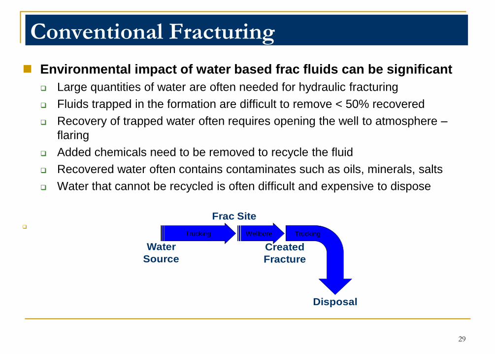
Environmental impact of water based frac fluids can be significant
Large quantities of water are often needed for hydraulic fracturing
Fluids trapped in the formation are difficult to remove < 50% recovered
Recovery of trapped water often requires opening the well to atmosphere –
flaring
Added chemicals need to be removed to recycle the fluid
Recovered water often contains contaminates such as oils, minerals, salts
Water that cannot be recycled is often difficult and expensive to dispose
Conventional Fracturing
Frac Site
Trucking Wellbore Trucking
Water
Source
Created
Fracture
Disposal
29

Environmental impact of LPG based frac fluids can be minimal.
Quantities of LPG needed for hydraulic fracturing can be lower
LPG is NOT trapped in the formation; easy to remove ~100% recovered
LPG is very light and mobile; avoids the need for flaring to recover
No contaminates such as minerals or salts are recovered with the LPG
LPG can be produced with the natural gas to the pipeline and recovered by gas
processing
LPG Fracturing
Refinery
Frac Site
Created
Fracture
Pipeline
30
LPG Frac Applications
Oil Wells – LPG is miscible in oils to thin the oils for enhanced recovery and
higher initial production rates
Re-Stimulation of Oil Wells – excellent fluid for re-stimulating of lower
pressure oil wells to improve production of existing wells
Under-pressured reservoirs for reduced hydrostatic during clean-up, plus
improved recovery rates
Recompletions with LPG recovery through existing facilities to recover all LPG
fluid to sales gas
Reservoirs that exhibit high capillary pressures with conventional fluids to
eliminate phase trapping
31
LPG Frac Applications
Exploration - pumping a completely reservoir compatible fluid that allows
excellent stimulation plus zero-damage evaluation
Multiple frac treatments completed without the need for immediate frac clean-
up between treatments
Sub-normally saturated reservoirs to eliminate altered saturations and
relative permeability effects – gas, oil and water
Low permeability reservoirs requiring long effective frac lengths to sustain
economic production
Improving cut-off parameters for economic recovery by providing effective
fracture stimulation otherwise unachievable with conventional fracturing
32
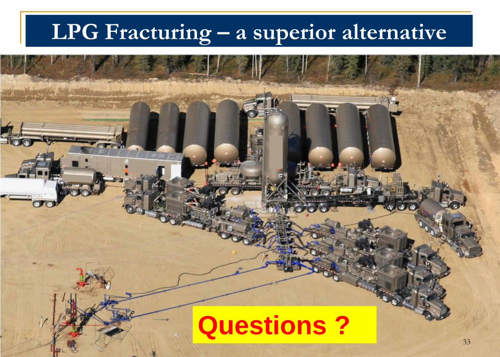
LPG Fracturing – a superior alternative
3333
Questions ?
Contact Information
Daniel PurvisUS Technical Advisor/[email protected]
Robert LestzChief Technology Officer [email protected]
Audis ByrdVice President & Chief Operating Officer 903-530-0625 [email protected]
34
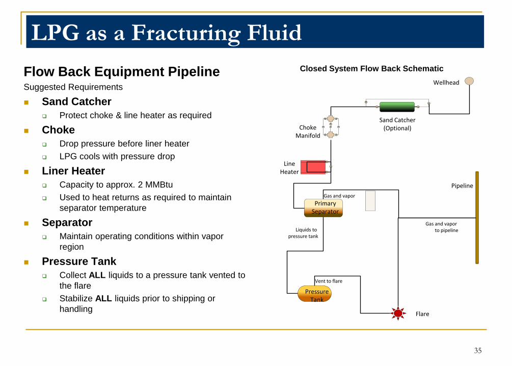
LPG as a Fracturing Fluid
Flow Back Equipment PipelineSuggested Requirements
Sand Catcher
Protect choke & line heater as required
Choke
Drop pressure before liner heater
LPG cools with pressure drop
Liner Heater
Capacity to approx. 2 MMBtu
Used to heat returns as required to maintain
separator temperature
Separator
Maintain operating conditions within vapor
region
Pressure Tank
Collect ALL liquids to a pressure tank vented to
the flare
Stabilize ALL liquids prior to shipping or
handling
Closed System Flow Back Schematic
35
Wellhead
Sand Catcher(Optional)Choke
Manifold
LineHeater
PrimarySeparator
PressureTank
Vent to flare
Flare
Liquids to pressure tank
Gas and vapor
Pipeline
Gas and vapor to pipeline
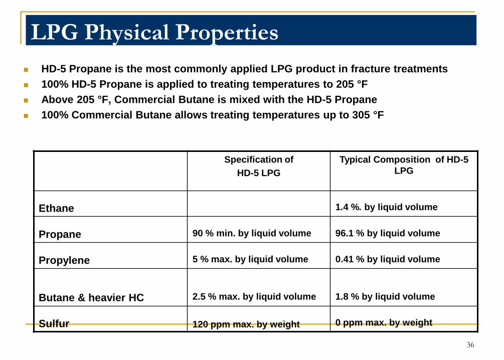
LPG Physical Properties
HD-5 Propane is the most commonly applied LPG product in fracture treatments
100% HD-5 Propane is applied to treating temperatures to 205 °F
Above 205 °F, Commercial Butane is mixed with the HD-5 Propane
100% Commercial Butane allows treating temperatures up to 305 °F
Specification of
HD-5 LPG
Typical Composition of HD-5
LPG
Ethane 1.4 %. by liquid volume
Propane 90 % min. by liquid volume 96.1 % by liquid volume
Propylene 5 % max. by liquid volume 0.41 % by liquid volume
Butane & heavier HC 2.5 % max. by liquid volume 1.8 % by liquid volume
Sulfur 120 ppm max. by weight 0 ppm max. by weight
36
0
5
10
15
20
25
0 30 60 90 120 150 180 210 240 270 300 330 360
Ga
s R
ate
(e³m
³/d
)
Time
750 mcf/d
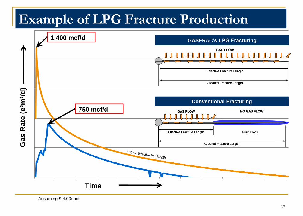
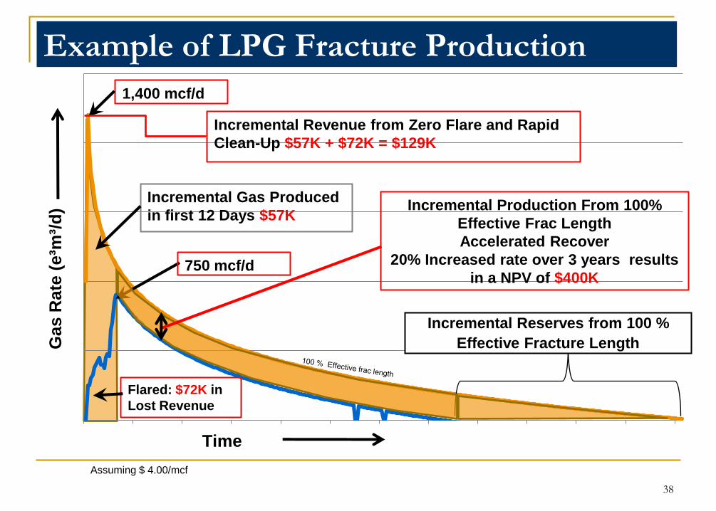
Example of LPG Fracture Production
Assuming $ 4.00/mcf
Fluid BlockEffective Fracture Length
Created Fracture Length
GAS FLOW NO GAS FLOW
Fluid BlockEffective Fracture Length
Created Fracture Length
GAS FLOW NO GAS FLOW
Conventional Fracturing
Effective Fracture Length
Created Fracture Length
GAS FLOW
Effective Fracture Length
Created Fracture Length
GAS FLOW
GASFRAC‟s LPG Fracturing1,400 mcf/d
37
0
5
10
15
20
25
0 30 60 90 120 150 180 210 240 270 300 330 360
Gas R
ate
(e³m
³/d
)
Time
Incremental Revenue from Zero Flare and Rapid
Clean-Up $57K + $72K = $129K
1,400 mcf/d
Incremental Gas Produced
in first 12 Days $57K
750 mcf/d
Incremental Production From 100%
Effective Frac Length
Accelerated Recover
20% Increased rate over 3 years results
in a NPV of $400K
Flared: $72K in
Lost Revenue
Example of LPG Fracture Production
Incremental Reserves from 100 %
Effective Fracture Length
Assuming $ 4.00/mcf
38
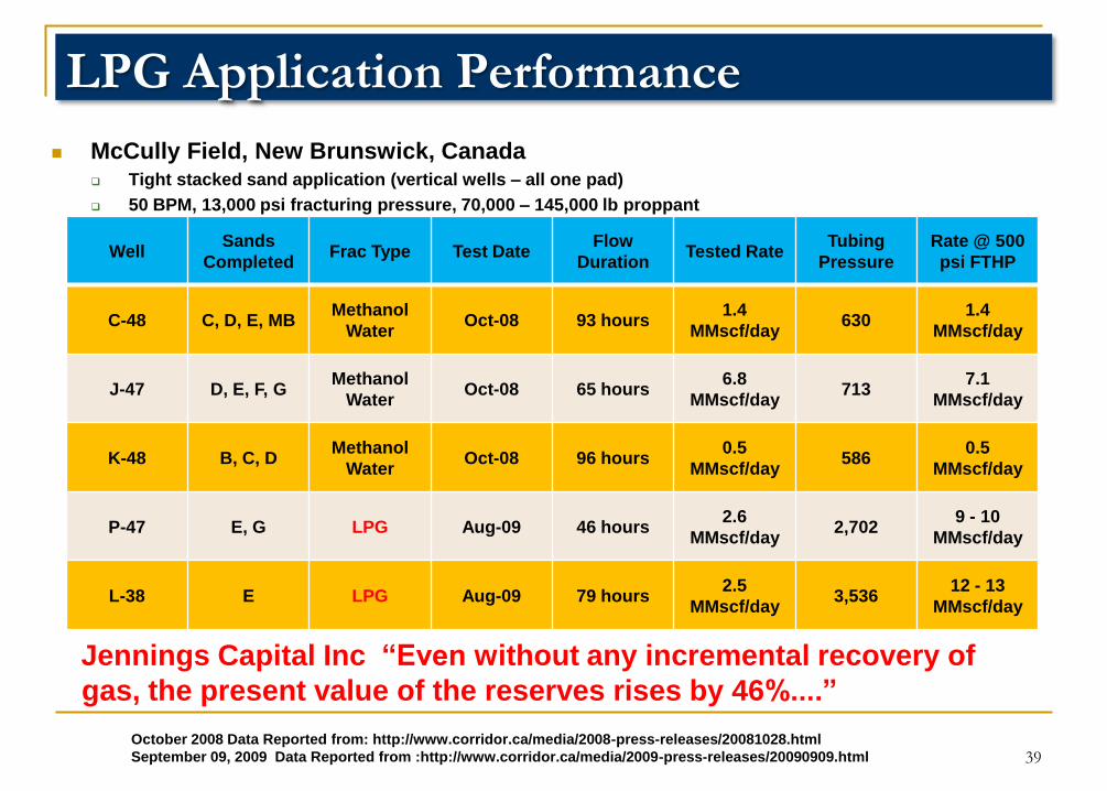
Jennings Capital Inc “Even without any incremental recovery of
gas, the present value of the reserves rises by 46%....”
WellSands
CompletedFrac Type Test Date
Flow
DurationTested Rate
Tubing
Pressure
Rate @ 500
psi FTHP
C-48 C, D, E, MBMethanol
WaterOct-08 93 hours
1.4
MMscf/day630
1.4
MMscf/day
J-47 D, E, F, GMethanol
WaterOct-08 65 hours
6.8
MMscf/day713
7.1
MMscf/day
K-48 B, C, DMethanol
WaterOct-08 96 hours
0.5
MMscf/day586
0.5
MMscf/day
P-47 E, G LPG Aug-09 46 hours2.6
MMscf/day2,702
9 - 10
MMscf/day
L-38 E LPG Aug-09 79 hours2.5
MMscf/day3,536
12 - 13
MMscf/day
McCully Field, New Brunswick, Canada Tight stacked sand application (vertical wells – all one pad)
50 BPM, 13,000 psi fracturing pressure, 70,000 – 145,000 lb proppant
LPG Application Performance
October 2008 Data Reported from: http://www.corridor.ca/media/2008-press-releases/20081028.html
September 09, 2009 Data Reported from :http://www.corridor.ca/media/2009-press-releases/20090909.html 39