waterlevelindicator
TRANSCRIPT

WATERLEVEL
INDICATORGROUP MEMBERS:
SHUBHI VERMA
SHRIYA SINGH
SAKSHI TYAGI
SMARTY SHARMA
Water Level Indicator With Alarm
The Water Level Indicator employs a simple mechanism to detect and indicate the water level in an overhead tank or any other water container. The sensing is done by using a set of three probes which are placed at three different levels on the tank walls (with probe 3 to probe 1 placed in increasing order of height, common probe (i.e. a supply carrying probe) is placed at the base of the tank). The level 3 represents the “tank full” condition while level 1 represents the “tank empty” condition.
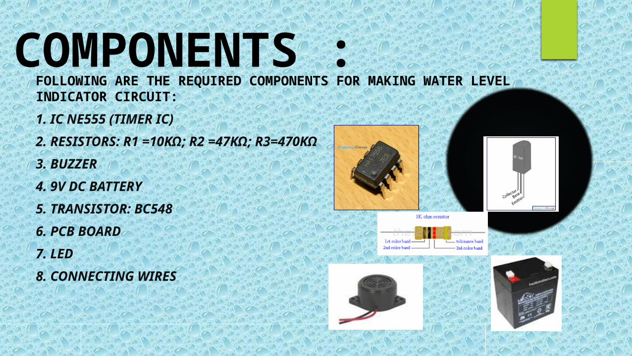
COMPONENTS :FOLLOWING ARE THE REQUIRED COMPONENTS FOR MAKING WATER LEVEL INDICATOR CIRCUIT:
1. IC NE555 (TIMER IC)
2. RESISTORS: R1 =10KΩ; R2 =47KΩ; R3=470KΩ
3. BUZZER
4. 9V DC BATTERY
5. TRANSISTOR: BC548
6. PCB BOARD
7. LED
8. CONNECTING WIRES

Circuit:
DETAILS OF COMPONENTS: IC NE555: The 555 can be used to provide time delays, as an
oscillator, and as a flip-flop element .It is a very commonly used IC for generating accurate timing pulses.
Resistors: Resistor is a passive component used to control current in a circuit .Its resistance is given by the ratio of voltage applied across its terminals to the current passing through it.
Buzzer: The buzzer produces sound. It is also used in alarm circuits.
Transistor: In this ckt we use bc548 transistor, which is a common emitter NPN transistor. This is basically used for amplification and switching purpose.
9V DC battery: It is a collection of one or more electrochemical cells in which stored chemical energy is converted into electrical energy . The principles of operation haven’t changed much since the time of Volta . Each cell consists of two half cells connected in series through an electrolytic solution.

IC 555
The 555 can be used to provide time delays, as an oscillation, and as a flip-flop element.
It is a very commonly used IC for generating accurate timing pulses.
It is an 8pin timer IC and has mainly two modes of operation: monostable and astable.
In monostable mode time delay of the pulses can be precisely controlled by an external resistor and a capacitor whereas in astable mode the frequency & duty cycle are controlled by two external resistors and a capacitor.

Pin diagram of IC 555

Circuit diagram:

WORKING:
The operation of this project is very simple and can be understood easily. In our project “water level indicator” there are 3 main conditions:
There is no water available in the source tank.
Intermediate level i.e. either of 3rd to 7th level.
There is ample amount of water available in the source tank.
So let us discuss on the more about these 3 conditions
Condition 1:Water is not available
When the tank is empty there is no conductive path between any of the 3 indicating probes and the common probe (which is connected to 9v+ supply) so the transistor base emitter region will not have sufficient biasing voltage hence it remains in cut off region and the output across its collector will be Vc approximately 9v and thus indicates, the tank is empty.

Condition 2: intermediate levels
Now as the water starts filling in the tank a conductive path is established between the sensing probes and the common probe and the corresponding transistors get sufficient biasing at their base, they starts conducting and now the outputs will be Vce (i.e. 1.2v-1.8v) approximately which is given to microcontroller. Here the microcontroller is programmed as a priority encoder which detects the highest priority input and displays corresponding water level in the seven segment display. In this project while the water level reaches the 7th level i.e. last but one level along with display in seven segment a discontinuous buzzer is activated which warns user that tank is going to be full soon.
Condition 3:Water full
When the tank becomes full, the top level probe gets the conductive path through water and the corresponding transistor gets into conduction whose output given to microcontroller with this input microcontroller not only displays the level in seven segment display but also activates the continuous buzzer by which user can understand that tank is full and can switch off the motor and save water.

Applications:
Automatic Water level Controller can be used in Hotels, Factories, Homes Apartments, Commercial Complexes, Drainage, etc., It can be fixed for single phase motor, Single Phase Submersibles, Three Phase motors. (For 3Æ and Single Phase Submersible Starter is necessary) and open well, Bore well and Sump. We can control two motor and two sumps and two overhead tanks by single unit.
Automatic water level controller will automatically START the pump set as soon as the water level falls below the predetermined level (usually 1/2 tank) and shall SWITCH OFF the pump set as soon as tank is full.
Fuel level indicator in vehicles.
Liquid level indicator in the huge containers in the companies.

Need of water level indicator:
Overflow problems
To prevent wastage of energy
To prevent wastage of water
Observation