watermaster electromagnetic flowmeter
TRANSCRIPT

— A B B M E A SU R EM ENT & A N A LY TI C S | US ER G U I DE SU PPLEM ENT | OI/FE X 10 0 H A RT- EN R E V. B
WaterMasterElectromagnetic flowmeter
WaterMaster FEX100 HART field device specification
Measurement made easy
—
WaterMaster electromagnetic flowmeter
Introduction
This User Guide Supplement provides HART® field device specification details for WaterMaster electromagnetic flowmeters. The AquaProbe sensor is available for operation with either a WaterMaster transmitter (FET100) or an AquaMaster3 transmitter (FET200).
For more information
Further publications are available for free download from:
www.abb.com/flow
or by scanning this code:
Search for or click on
Data Sheet DS/FEA100-ENAquaProbe FEA100Insertion-type electromagneticflow sensor with WaterMaster transmitter
User Guide OI/FET100-ENWaterMaster FET100Electromagnetic flowmeter transmitter
Programming Guide IM/WMPWaterMaster Electromagnetic flowmeter
Related documents
WaterMaster flowmeter (FEA100) Search for or click on
User Guide SupplementWaterMaster FEX100–MBElectromagnetic flowmeter | MODBUS RS485 Physical Layer
COI/FEX100/MOD-EN
MODBUS Tables SupplementWaterMasterElectromagnetic flowmeter
COI/FEX100/MOD/TBL-EN
User Guide SupplementWaterMaster Electromagnetic flowmeter | PROFIBUS RS485 Physical Layer (FEX100-DP)
IM/WMPBS-EN
User Guide Supplement WaterMaster Electromagnetic flowmeter | PROFIBUS FEX100-DP parameter tables
IM/WMPBST-EN
ScrewDriver profiling and configuration software Search for or click on
User GuideScrewDriver 7Diagnostic and Flow-Profiling Software for ABB Flowmeters
IM/SDR
WaterMaster FEX100 HART Field Device Specification
OI/FEX100HART-EN Rev. B 1
Table of contents
1. Introduction ..................................................................................................................................................................... 41.1 Scope ................................................................................................................................................................ 41.2 Purpose ............................................................................................................................................................. 41.3 Who should use this document? ........................................................................................................................ 41.4 Abbreviations and definitions .............................................................................................................................. 41.5 References ........................................................................................................................................................ 5
2. Device Identification ........................................................................................................................................................ 63. Product Overview ............................................................................................................................................................ 64. Product Interfaces ........................................................................................................................................................... 6
4.1 Process Interface ............................................................................................................................................... 64.1.1 Sensor Input Channel...................................................................................................................... 6
4.2 Host interface .................................................................................................................................................... 64.2.1 Current Output ................................................................................................................................ 64.2.2 Pulse Output 1 / Logic Output 1 ...................................................................................................... 74.2.3 Pulse Output 2 / Logic Output 2 ...................................................................................................... 74.2.4 Logic Output 3 ................................................................................................................................ 74.2.5 Infra-Red Service Port ..................................................................................................................... 7
4.3 Local Interfaces, Jumpers and Switches ............................................................................................................ 74.3.1 Local Controls and Displays ............................................................................................................ 74.3.2 Internal Jumpers and Switches ....................................................................................................... 7
5. Device Variables .............................................................................................................................................................. 86. Dynamic Variables ........................................................................................................................................................... 87. Status Information ........................................................................................................................................................... 9
7.1 Device Status .................................................................................................................................................... 97.2 Additional Device Status (Command #48) ........................................................................................................ 10
8. Common-Practice Commands ...................................................................................................................................... 138.1 Supported Commands .................................................................................................................................... 13
8.1.1 Command 33 Read Transmitter Variables ..................................................................................... 138.1.2 Command 35 Write Range Values ................................................................................................ 138.1.3 Command 38 Reset “Configuration Changed” Flag ...................................................................... 138.1.4 Command 44 Write PV Units ........................................................................................................ 13
8.2 Burst Mode ...................................................................................................................................................... 138.3 Catch Device Variable ...................................................................................................................................... 14
9. Device-Specific Commands .......................................................................................................................................... 159.1 Command #128: Read Eight-Bit ...................................................................................................................... 169.2 Command #129: Write Eight-Bit ...................................................................................................................... 179.3 Command #130: Read Sixteen-Bit ................................................................................................................... 239.4 Command #132: Read Single-Precision Floating-Point with Unit ...................................................................... 24
WaterMaster FEX100 HART Field Device Specification
2 OI/FEX100HART-EN Rev. B
9.5 Command #133: Write Single-Precision Floating-Point with Unit ...................................................................... 259.6 Command #134: Read Single-Precision Floating-Point ..................................................................................... 309.7 Command #135: Write Single-Precision Floating-Point ..................................................................................... 319.8 Command #136: Read String........................................................................................................................... 329.9 Command #137: Write String ........................................................................................................................... 339.10 Command #138: Read Double-Precision Floating-Point with Unit .................................................................... 359.11 Command #143: Trigger Action ...................................................................................................................... 369.12 Command #146: Read Thirty-Two-Bit ............................................................................................................. 379.13 Command #148: Read Twenty-Four-Bit Id ...................................................................................................... 389.14 Command #150: Read Dynamic Single-Precision Floating-Point Range .......................................................... 399.15 Command #180: Trigger Adjust Function ........................................................................................................ 409.16 Command #181: Read Adjust Values .............................................................................................................. 419.17 Command #182: Read Additional Diagnostic Information ................................................................................ 42
10. Tables ....................................................................................................................................................................... 4410.1 Security Mode ................................................................................................................................................... 4410.2 Current Output Alarm Selection ......................................................................................................................... 4410.3 Current Output Mode ......................................................................................................................................... 4410.4 Enable State ...................................................................................................................................................... 4410.5 Simulation Mode ................................................................................................................................................ 4410.6 Device Calibration Location ................................................................................................................................ 4410.7 Sensor Lining Materials ...................................................................................................................................... 4610.8 Sensor Electrode Materials ................................................................................................................................ 4610.9 Sensor Calibration Mode .................................................................................................................................... 4710.10 Sensor Calibration Type ................................................................................................................................... 4710.11 Current Output Empty Pipe Behaviour ............................................................................................................. 4710.12 Logic Output 1 Alarm Behaviour ...................................................................................................................... 4710.13 Logic Output 2 Alarm Behaviour ...................................................................................................................... 4710.14 Logic Output 3 Alarm Behaviour ...................................................................................................................... 4710.15 Diagnostic Alarm Simulation ............................................................................................................................. 4810.16 Logic Output Simulation ................................................................................................................................... 5010.17 Logic Output State........................................................................................................................................... 5010.18 Logic Output Signal Source ............................................................................................................................. 5010.19 Logic Output Action State ................................................................................................................................ 5010.20 Digital Output Function .................................................................................................................................... 5010.21 Digital Output Pulse Mode ............................................................................................................................... 5010.22 Language ........................................................................................................................................................ 5010.23 Operator Page Line Items ................................................................................................................................ 5110.24 Operator Page 1 Display Modes ...................................................................................................................... 5110.25 Operator Pages 2 & 3 Display Modes ............................................................................................................... 5110.26 Display Decimal Point Settings ......................................................................................................................... 5110.27 Display Date Formats ....................................................................................................................................... 51

WaterMaster FEX100 HART Field Device Specification
OI/FEX100HART-EN Rev. B 3
10.28 Mains Frequency ............................................................................................................................................. 5310.29 Drive Mode ...................................................................................................................................................... 5310.30 Sensor Type .................................................................................................................................................... 5310.31 Sensor Bore Size ............................................................................................................................................. 5410.32 Flow Direction .................................................................................................................................................. 5610.33 Meter Mode ..................................................................................................................................................... 5610.34 Velocity Units ................................................................................................................................................... 5610.35 Volume Flow Units ........................................................................................................................................... 5710.36 Service Port Baudrates .................................................................................................................................... 5810.37 Volume Totalizer Units ..................................................................................................................................... 5810.38 Read-Only Switch Status ................................................................................................................................. 5810.39 Adjustment Operation Result ........................................................................................................................... 5810.40 MID Meter Mode ............................................................................................................................................. 58
11. Unit Conversion ............................................................................................................................................................ 5911.1 Conversion factors for volume flow units from l/s ............................................................................................. 6011.2 Conversion factors for volume flow units to l/s ................................................................................................. 6111.3 Conversion factors for velocity units from m/s ................................................................................................. 6211.4 Conversion factors for velocity units to m/s ..................................................................................................... 6211.5 Conversion factors for volume units from l ....................................................................................................... 6211.6 Conversion factors for volume units to l ........................................................................................................... 63
12. Performance ................................................................................................................................................................. 6412.1 Sampling Rates .............................................................................................................................................. 6412.2 Power-Up ....................................................................................................................................................... 6412.3 Self-Test ......................................................................................................................................................... 6412.4 Command Response Times ............................................................................................................................ 6412.5 Busy and Delayed-Response .......................................................................................................................... 6412.6 Long Messages .............................................................................................................................................. 6412.7 Non-Volatile Memory ...................................................................................................................................... 6512.8 Modes ............................................................................................................................................................ 6512.9 Write Protection .............................................................................................................................................. 6512.10 Damping ......................................................................................................................................................... 65
Annex A. Capability Checklist ......................................................................................................................................... 66Annex B. Default Configuration ...................................................................................................................................... 67
WaterMaster FEX100 HART Field Device Specification
4 OI/FEX100HART-EN Rev. B
1. Introduction
1.1 Scope The ABB WaterMaster, model FEX100, device revision 0 complies with HART® Protocol Revision 5.7. This document specifies all the device specific features and documents HART Protocol implementation details (e.g., the Engineering Unit Codes supported). The functionality of this Field Device is described sufficiently to allow its proper application in a process and its complete support in HART capable Host Applications.
1.2 Purpose This specification is designed to compliment other documentation (e.g., the WaterMaster Instruction Manual) by providing a complete, unambiguous description of this Field Device from a HART Communication perspective.
1.3 Who should use this document? The specification is designed to be a technical reference for HART capable Host Application Developers, System Integrators and knowledgeable End Users. It also provides functional specifications (e.g., commands, enumerations and performance requirements) used during Field Device development, maintenance and testing. This document assumes the reader is familiar with HART Protocol requirements and terminology.
1.4 Abbreviations and definitions
CPU Central Processing Unit (of microprocessor).
EEPROM Electrically-Erasable Read-Only Memory.
FSK Frequency Shift Keying.
NAMUR Normenarbeitsgemeinschaft für Mess- Und Regeltechnik in der Chemischen Industrie.
Process control standardisation group based in Germany.
PV Primary Variable.
QV Quaternary Variable.
RAM Random Access Memory.
ROM Read-Only Memory.
SV Secondary Variable.
TV Tertiary Variable.

WaterMaster FEX100 HART Field Device Specification
OI/FEX100HART-EN Rev. B 5
1.5 References
[A] HART Smart Communications Protocol Specification. HCF_SPEC-13. Available from the HCF.
[B] ABB WaterMaster Electromagnetic Flowmeter Data Sheet, Document DS/WM, Revision D. Available from ABB website.
[C] ABB WaterMaster Electromagnetic Flowmeter Programming Guide, Document IM/WMP Revision C. Available from ABB website.
[D] ABB WaterMaster Electromagnetic Flowmeter Instruction Manual, Document IM/WM Revision E. Available from ABB website.
[E] NE107 – Self Monitoring and Diagnosis of Field Devices. Available from NAMUR website.
[F] NE043 – Standardization of the Signal Level for the Failure Information of Digital Transmitters. Available from NAMUR website.
[G] ISO 80000-3:2006 – Quantities and units – Part 3: Space and time. Available from ISO website.
[H] NIST Special Publication 811 – Guide for the Use of the International System of Units (SI). Available from the NIST website.

WaterMaster FEX100 HART Field Device Specification
6 OI/FEX100HART-EN Rev. B
2. Device Identification
Manufacturer Name: ABB Model Name(s): FEX100 WaterMaster
Manufacture ID Code: 26 (1A Hex) Device Type Code: 31 (1F Hex)
HART Protocol Revision 5.7 Device Revision: 0
Number of Device Variables 6
Physical Layers Supported FSK
Physical Device Category Transmitter, Current Output
3. Product Overview The WaterMaster is an electromagnetic flowmeter with a 4-to-20mA output, with either a remote or integrated sensor.
The analogue output of the device is linear with flow over the user-defined working range.
4. Product Interfaces
4.1 Process Interface
4.1.1 Sensor Input Channel Integrated sensors are pre-wired at the factory. For remote sensors, the terminals marked “M1”, “M2”, “SCR”, “D1/TFE”, “D2”, “3”, “S2”, “E2”, “E1” and “S1” are used for connection to the sensor. Refer to [D] for details.
4.2 Host interface
4.2.1 Current Output This output corresponds to the Primary Variable with HART Communication also being supported on this loop. It implements levels as defined in the NAMUR standard NE043, refer to [F] for further details.
The two-wire 4-to-20mA current loop is connected on two terminals marked "31" and "32". Refer to [D] for connection details.
Three modes of operation are available – “4 to 20”, “4 to 12 to 20” and "4 to 20 FWD/REV". For “4 to 12 to 20” mode, negative flow values are represented by 4 to 12mA, and positive flow values by 12 to 20mA. In “4 to 20” mode, only positive values are represented. "4 to 20 FWD/REV" mode is used to represent both positive and negative values.
Device malfunction can be indicated by down-scale or up-scale current, with the direction being selectable by the user.
Refer to [C] for full details of configuring the Current Output.
WaterMaster FEX100 HART Field Device Specification
OI/FEX100HART-EN Rev. B 7
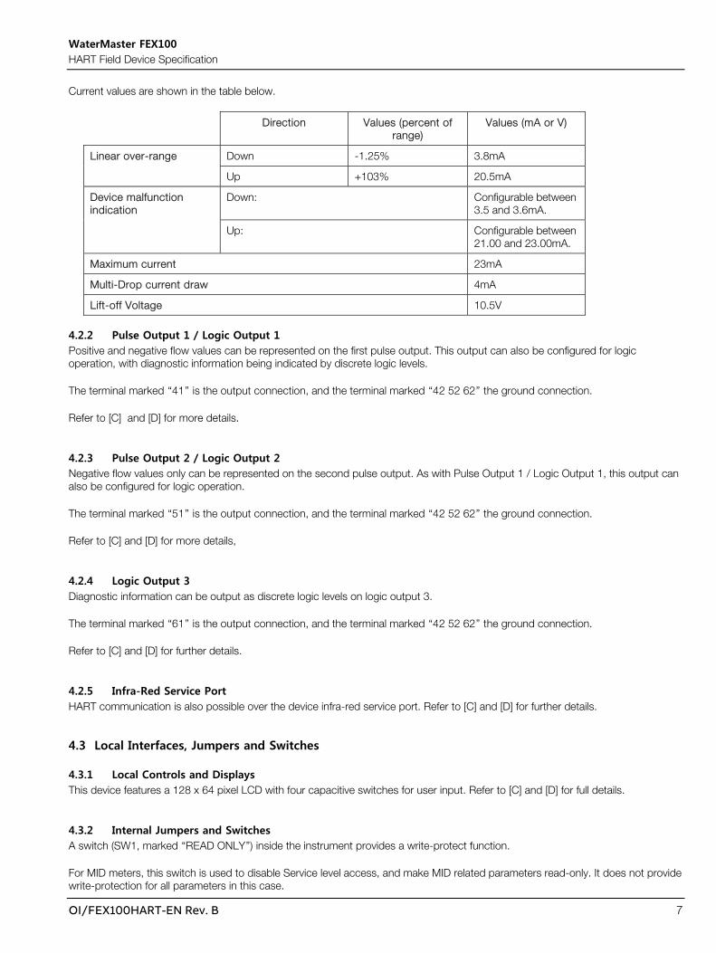
Current values are shown in the table below.
Direction Values (percent of range)
Values (mA or V)
Linear over-range Down -1.25% 3.8mA
Up +103% 20.5mA
Device malfunction indication
Down: Configurable between 3.5 and 3.6mA.
Up: Configurable between 21.00 and 23.00mA.
Maximum current 23mA
Multi-Drop current draw 4mA
Lift-off Voltage 10.5V
4.2.2 Pulse Output 1 / Logic Output 1 Positive and negative flow values can be represented on the first pulse output. This output can also be configured for logic operation, with diagnostic information being indicated by discrete logic levels.
The terminal marked “41” is the output connection, and the terminal marked “42 52 62” the ground connection.
Refer to [C] and [D] for more details.
4.2.3 Pulse Output 2 / Logic Output 2 Negative flow values only can be represented on the second pulse output. As with Pulse Output 1 / Logic Output 1, this output can also be configured for logic operation.
The terminal marked “51” is the output connection, and the terminal marked “42 52 62” the ground connection.
Refer to [C] and [D] for more details,
4.2.4 Logic Output 3 Diagnostic information can be output as discrete logic levels on logic output 3.
The terminal marked “61” is the output connection, and the terminal marked “42 52 62” the ground connection.
Refer to [C] and [D] for further details.
4.2.5 Infra-Red Service Port HART communication is also possible over the device infra-red service port. Refer to [C] and [D] for further details.
4.3 Local Interfaces, Jumpers and Switches
4.3.1 Local Controls and Displays This device features a 128 x 64 pixel LCD with four capacitive switches for user input. Refer to [C] and [D] for full details.
4.3.2 Internal Jumpers and Switches A switch (SW1, marked “READ ONLY”) inside the instrument provides a write-protect function.
For MID meters, this switch is used to disable Service level access, and make MID related parameters read-only. It does not provide write-protection for all parameters in this case.

WaterMaster FEX100 HART Field Device Specification
8 OI/FEX100HART-EN Rev. B
Refer to [D] for details. See also Section 12.9.
5. Device Variables Refer to 8.1.1 for details of device variables.
6. Dynamic Variables Four Dynamic Variables are implemented, as shown in the table below.
Meaning Units
PV Volume Flow Refer to Table 10.35, Volume Flow Units.
SV Flow Velocity Refer to Table 10.34, Velocity Units.
TV Volume Forward Totalizer Refer to Table 10.37, Volume Totalizer Units.
QV Volume Reverse Totalizer Refer to Table 10.37, Volume Totalizer Units.

WaterMaster FEX100 HART Field Device Specification
OI/FEX100HART-EN Rev. B 9
7. Status Information Alarm conditions are categorized into groups and classes as defined in the NAMUR standard NE107. Refer to [E] for further details.
7.1 Device Status Bit 7 (“Device Malfunction”) is set when any diagnostic alarm of class “Failure” occurs.
Bit 4 ("More Status Available") is set whenever any diagnostic alarm is annunciated.
Command #48 gives further detail. (Refer to 7.2).
WaterMaster FEX100 HART Field Device Specification
10 OI/FEX100HART-EN Rev. B
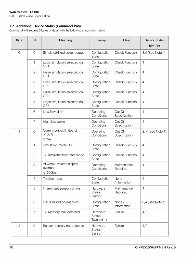
7.2 Additional Device Status (Command #48) Command #48 returns 6 bytes of data, with the following status information:
Byte Bit Meaning Group Class Device Status
Bits Set
0 0 Simulated/fixed current output Configuration State
Check Function 3,4 (See Note 1)
1 Logic simulation selected on OP1
Configuration State
Check Function 4
2 Pulse simulation selected on OP1
Configuration State
Check Function 4
3 Logic simulation selected on OP2
Configuration State
Check Function 4
4 Pulse simulation selected on OP2
Configuration State
Check Function 4
5 Logic simulation selected on OP3
Configuration State
Check Function 4
6 Low flow alarm Operating Conditions
Out Of Specification
4
7 High flow alarm Operating Conditions
Out Of Specification
4
1 0 Current output limited Q >103% Qmax
Operating Conditions
Out Of Specification
2, 4 (See Note 1)
1 Simulation mode On Configuration State
Check Function 4
2 Tx. simulator/calibrator mode Configuration State
Check Function 4
3 At Qmax, volume display overrun <1600hrs
Operating Conditions
Maintenance Required
4
4 Totalizer reset Configuration State
None /Information
4
5 Intermittent sensor comms Hardware Status Sensor
Maintenance Required
4
6 HART multidrop enabled Configuration State
None / Information
3,4 (See Note 1)
7 Tx. Memory fault detected Hardware Status Transmitter
Failure 4,7
2 0 Sensor memory not detected Hardware Status Sensor
Failure 4,7

WaterMaster FEX100 HART Field Device Specification
OI/FEX100HART-EN Rev. B 11
Byte Bit Meaning Group Class Device Status
Bits Set
1 Tx. Measurement suspended Operating Conditions
Failure 4,7
2 Empty pipe Operating Conditions
Out Of Specification
4
3 Not used - - -
4 Not used - - -
5 Open circuit electrode Operating Conditions
Out Of Specification
4
6 Short circuit electrode Operating Conditions
Out Of Specification
4
7 Not used - - -
3 0 Installation fault/condition. Operating Conditions
Failure 4,7
1 Open circuit coil/wiring. Operating Conditions
Failure 4,7
2 Short circuit coil/wiring Operating Conditions
Failure 4,7
3 Check cable+coil resistance Operating Conditions
Failure 4,7
4 Transmitter hardware fault Hardware Status Transmitter
Failure 4,7
5 Bad flow data Operating Conditions
Failure 4,7
6 Accuracy warning? Operating Conditions
Out Of Specification
4
7 OIML self-check limits exceeded
Hardware Status Transmitter
Maintenance Required
4
4 0 Measurement starting Hardware Status Transmitter
Out Of Specification
4
1 Current output hardware fault Hardware Status Transmitter
Maintenance Required
4
2 Sensor setup not complete Hardware Status Sensor
Out Of Specification
4
3 Incompatible sensor Hardware Status Sensor
Failure 4,7
WaterMaster FEX100 HART Field Device Specification
12 OI/FEX100HART-EN Rev. B
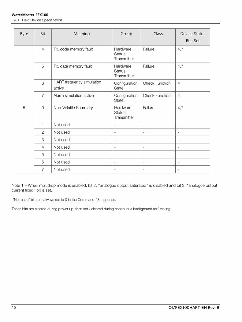
Byte Bit Meaning Group Class Device Status
Bits Set
4 Tx. code memory fault Hardware Status Transmitter
Failure 4,7
5 Tx. data memory fault Hardware Status Transmitter
Failure 4,7
6 HART frequency simulation active
Configuration State
Check Function 4
7 Alarm simulation active Configuration State
Check Function 4
5 0 Non-Volatile Summary Hardware Status Transmitter
Failure 4,7
1 Not used - - -
2 Not used - - -
3 Not used - - -
4 Not used - - -
5 Not used - - -
6 Not used - - -
7 Not used - - -
Note 1 – When multidrop mode is enabled, bit 2, “analogue output saturated” is disabled and bit 3, “analogue output current fixed” bit is set.
"Not used" bits are always set to 0 in the Command 48 response.
These bits are cleared during power up, then set / cleared during continuous background self-testing.

WaterMaster FEX100 HART Field Device Specification
OI/FEX100HART-EN Rev. B 13
8. Common-Practice Commands
8.1 Supported Commands The following common-practice commands are implemented:
33 Read Transmitter Variables
34 Write Damping Value
35 Write Range Values
36 Set Upper Range Value
38 Reset "Configuration Changed" Flag
40 Enter/Exit Fixed Current Mode
44 Write PV Units
48 Read Additional Device Status
8.1.1 Command 33 Read Transmitter Variables The following variables are available for use with Command 33.
Slot Name Description
0 Volume Flow Device PV, refer to Table 10.35 for supported units.
1 Flow Velocity Device SV, refer to Table 10.34 for supported units.
2 Q% Percentage of range. Units fixed to % (HART unit code 57).
3 Volume Forward Device TV, refer to Table 10.37 for supported units.
4 Volume Reverse Device QV, refer to Table 10.37 for supported units.
5 Volume Net Sum of Forward and Reverse Volume totalizers, refer to Table 10.37 for supported units.
Any combination of up to four of the above variables can be requested at once using command 33.
8.1.2 Command 35 Write Range Values The lower range value is fixed to 0.
8.1.3 Command 38 Reset “Configuration Changed” Flag The “Configuration Changed” flag is only affected by changes to the device configuration made with HART.
8.1.4 Command 44 Write PV Units Refer to Table 10.35 for details of supported volume flow units.
8.2 Burst Mode This Field Device does not support Burst Mode.

WaterMaster FEX100 HART Field Device Specification
14 OI/FEX100HART-EN Rev. B
8.3 Catch Device Variable This Field Device does not support Catch Device Variable.

WaterMaster FEX100 HART Field Device Specification
OI/FEX100HART-EN Rev. B 15
9. Device-Specific Commands The following device-specific commands are implemented:
128 Read Eight-Bit
129 Write Eight-Bit
130 Read Sixteen-Bit
132 Read Single-Precision Floating-Point with Unit
133 Write Single-Precision Floating-Point with Unit
134 Read Single-Precision Floating-Point
135 Write Single-Precision Floating-Point
136 Read String
137 Write String
138 Read Double-Precision Floating-Point with Unit
143 Trigger Action
146 Read Thirty-Two-Bit
148 Read Twenty-Four-Bit ID
150 Read Dynamic Single-Precision Floating-Point Range
180 Trigger Adjust Function
181 Read Adjust Values
182 Additional Diagnostic Information

WaterMaster FEX100 HART Field Device Specification
16 OI/FEX100HART-EN Rev. B
9.1 Command #128: Read Eight-Bit Reads an eight-bit variable.
Request Data Bytes
Byte Format Description
0 Byte Slot number of the variable to read.
Response Data Bytes
Byte Format Description
0 Byte Slot number of the variable.
1 Byte The requested variable value.
Command-Specific Response Codes
Code Class Description
0 Success No Command-Specific Errors.
2 Error Invalid Selection.
5 Error Too Few Data Bytes Received.

WaterMaster FEX100 HART Field Device Specification
OI/FEX100HART-EN Rev. B 17
9.2 Command #129: Write Eight-Bit Writes an eight-bit variable.
Request Data Bytes
Byte Format Description
0 Byte Slot number of the variable to write.
1 Byte Value of the variable to write.
Response Data Bytes
Byte Format Description
0 Byte Slot number of the variable.
1 Byte The value of the variable after the write has completed.
Command-Specific Response Codes
Code Class Description
0 Success No Command-Specific Errors.
2 Error Invalid Selection.
3 Error Passed Parameter Too Large.
4 Error Passed Parameter Too Small.
5 Error Too Few Data Bytes Received.
7 Error In Write Protect Mode.
16 Error Access Restricted.

WaterMaster FEX100 HART Field Device Specification
18 OI/FEX100HART-EN Rev. B
Command 128/129 Slot Content
Slot Name Description Access Upper
Limit
Lower
Limit
0 Security Mode The current security mode of the device. (Refer to 10.1 Security Mode).
RO - -
6 Iout For Alarm The Current Output setting for general alarms. (Refer to 10.2 Current Output Alarm Selection).
R/W - -
7 Current Output Mode
The operating mode of the Current Output. (Refer to 10.3 Current Output Mode).
R/W - -
9 Cyclic Data Output Flow Group
The enable/disable state of the Flow group for the Cyclic Data Output. (Refer to 10.4 Enable State).
R/W - -
10 Cyclic Data Output Vol. Totals Group
The enable/disable state of the Volume Totals group for the Cyclic Data Output. (Refer to 10.4 Enable State).
R/W - -
12 Cyclic Data Output Outputs Group
The enable/disable state of the Outputs group for the Cyclic Data Output. (Refer to 10.4 Enable State).
R/W - -
13 Cyclic Data Output Electrodes Group
The enable/disable state of the Electrodes group for the Cyclic Data Output. (Refer to 10.4 Enable State).
R/W - -
16 Cyclic Data Output Status Group
The enable/disable state of the Status group for the Cyclic Data Output. (Refer to 10.4 Enable State).
R/W - -
17 Cyclic Data Output Coil Group
The enable/disable state of the Coil group for the Cyclic Data Output. (Refer to 10.4 Enable State).
R/W - -
18 Cyclic Data Output TX Group
The enable/disable state of the Transmitter group for the Cyclic Data Output. (Refer to 10.4 Enable State).
R/W - -
20 Simulation Mode The active simulation mode. (Refer to 10.5 Simulation Mode).
R/W - -
21 PCB The hardware version number of the transmitter.
RO - -
24 Transmitter Last Calibration Location
The last location of transmitter calibration. (Refer to 10.6 Device Calibration Location).
RO - -
26 Sensor First Calibration Location
The initial location of the sensor calibration. (Refer to 10.6 Device Calibration Location).
RO - -
27 Sensor Last Calibration Location
The last location of the sensor calibration. (Refer to 10.6 Device Calibration Location).
RO - -
28 Sensor Lining Material
The materials used in construction of the sensor lining. (Refer to 10.7 Sensor Lining Materials).
RO - -
29 Sensor Electrode Material
The materials used in construction of the sensor electrodes. (Refer to 10.8 Sensor Electrode Materials).
RO - -

WaterMaster FEX100 HART Field Device Specification
OI/FEX100HART-EN Rev. B 19
Slot Name Description Access Upper
Limit
Lower
Limit
30 Sensor Cal. Mode
The mode the sensor was last calibrated in. (Refer to
10.9 Sensor Calibration Mode).
RO - -
32 Sensor Cal. Type
The type of calibration performed for the device sensor. (Refer to 10.10 Sensor Calibration Type).
RO - -
38 Iout For EP Alarm
The setting of the Current Output in empty pipe alarm conditions. (Refer to 10.11 Current Output Empty Pipe Behaviour).
R/W - -
41 DO1 Config Alarm
The setting of Logic Output 1 in general alarm conditions. (Refer to 10.12 Logic Output 1 Alarm Behaviour).
R/W - -
42 DO1 Config Empty Pipe
The setting of Logic Output 1 in empty pipe alarm conditions. (Refer to 10.12 Logic Output 1 Alarm Behaviour).
R/W - -
44 DO1 Config Min. Alarm
The setting of Logic Output 1 in minimum flow alarm conditions. (Refer to 10.12 Logic Output 1 Alarm Behaviour).
R/W - -
45 DO1 Config Max. Alarm
The setting of Logic Output 1 in maximum flow alarm conditions. (Refer to 10.12 Logic Output 1 Alarm Behaviour).
R/W - -
46 DO2 Config Alarm
The setting of Logic Output 2 in general alarm conditions. (Refer to 10.13 Logic Output 2 Alarm Behaviour).
R/W - -
47 DO2 Config Empty Pipe
The setting of Logic Output 2 in empty pipe alarm conditions. (Refer to 10.13 Logic Output 2 Alarm Behaviour).
R/W - -
49 DO2 Config Min. Alarm
The setting of Logic Output 2 in minimum flow alarm conditions. (Refer to 10.13 Logic Output 2 Alarm Behaviour).
R/W - -
50 DO2 Config Max. Alarm
The setting of Logic Output 2 in maximum flow alarm conditions. (Refer to 10.13 Logic Output 2 Alarm Behaviour).
R/W - -
51 DO3 Config Alarm
The setting of Logic Output 3 in general alarm conditions. (Refer to 10.14 Logic Output 3 Alarm Behaviour).
R/W - -
52 DO3 Config Empty Pipe
The setting of Logic Output 3 in empty pipe alarm conditions. (Refer to 10.14 Logic Output 3 Alarm Behaviour).
R/W - -
54 DO3 Config Min. Alarm
The setting of Logic Output 3 in minimum flow alarm conditions. (Refer to 10.14 Logic Output 3 Alarm Behaviour).
R/W - -
55 DO3 Config Max. Alarm
The setting of Logic Output 3 in maximum flow alarm conditions. (Refer to 10.14 Logic Output 3 Alarm Behaviour).
R/W - -
56 Alarm Simulation The current simulated Diagnostic alarm. (Refer to 10.15 Diagnostic Alarm Simulation).
Note – this parameter is read-only for MID flowmeters.
R/W - -

WaterMaster FEX100 HART Field Device Specification
20 OI/FEX100HART-EN Rev. B
Slot Name Description Access Upper
Limit
Lower
Limit
57 Group Masking Check Function
The setting of the Check Function group Diagnostic alarm mask. (Refer to 10.4 Enable State).
R/W - -
58 Group Masking Off Specification
The setting of the Off Specification group Diagnostic alarm mask. (Refer to 10.4 Enable State).
R/W - -
59 Group Masking Maintenance
The setting of the Maintenance group Diagnostic alarm mask. (Refer to 10.4 Enable State).
R/W - -
60 Individual Masking Overrange 103%
The setting of the mask for the Overrange 103% alarm. (Refer to 10.4 Enable State).
R/W - -
61 Individual Masking Min. Alarm
The setting of the mask for the Min. Flow alarm. (Refer to 10.4 Enable State).
R/W - -
62 Individual Masking Max. Alarm
The setting of the mask for the Max. Flow alarm. (Refer to 10.4 Enable State).
R/W - -
68 Simulation Logic 1
The logic level requested for simulation on Logic Output 1. (Refer to 10.16 Logic Output Simulation).
R/W - -
70 Simulation Logic 2
The logic level requested for simulation on Logic Output 2. (Refer to 10.16 Logic Output Simulation).
R/W - -
72 Simulation Logic 3
The logic level requested for simulation on Logic Output 3. (Refer to 10.16 Logic Output Simulation).
R/W - -
73 DO1 State The logic level on Logic Output 1. (Refer to 10.17 Logic Output State).
RO - -
74 DO2 State The logic level on Logic Output 2. (Refer to 10.17 Logic Output State).
RO - -
75 DO3 State The logic level on Logic Output 3. (Refer to 10.17 Logic Output State).
RO - -
77 DO1 Logic The signal source used to operate Logic Output 1. (Refer to 10.18 Logic Output Signal Source).
R/W - -
78 DO1 Action The output of Logic Output 1 under action conditions. (Refer to 10.19 Logic Output Action State).
R/W - -
80 DO2 Logic The signal source used to operate Logic Output 2. (Refer to 10.18 Logic Output Signal Source).
R/W - -
81 DO2 Action The output of Logic Output 2 under action conditions. (Refer to 10.19 Logic Output Action State).
R/W - -
83 DO3 Logic The signal source used to operate Logic Output 3. (Refer to 10.18 Logic Output Signal Source).
R/W - -
84 DO3 Action The output of Logic Output 3 under action conditions. (Refer to 10.19 Logic Output Action State).
R/W - -

WaterMaster FEX100 HART Field Device Specification
OI/FEX100HART-EN Rev. B 21
Slot Name Description Access Upper
Limit
Lower
Limit
85 DO1/DO2 Function
The operating mode of Digital Outputs 1 and 2. (Refer to 10.20 Digital Output Function).
R/W - -
86 Pulse Mode The mode of pulse operation of Digital Outputs 1 and 2. (Refer to 10.21 Digital Output Pulse Mode).
R/W - -
93 Language The language of the local device display. (Refer to 10.22 Language).
R/W - -
94 Operator Page 1 1st Line
The value being displayed on line 1 of device display Operator Page 1. (Refer to 10.23 Operator Page Line Items).
R/W - -
95 Operator Page 1 2nd Line
The value being displayed on line 2 of device display Operator Page 1. (Refer to 10.23 Operator Page Line Items).
R/W - -
96 Operator Page 1 3rd Line
The value being displayed on line 3 of device display Operator Page 1. (Refer to 10.23 Operator Page Line Items).
R/W - -
98 Operator Page 2 1st Line
The value being displayed on line 1 of device display Operator Page 2. (Refer to 10.23 Operator Page Line Items).
R/W - -
99 Operator Page 2 2nd Line
The value being displayed on line 2 of device display Operator Page 2. (Refer to 10.23 Operator Page Line Items).
R/W - -
100 Operator Page 2 3rd Line
The value being displayed on line 3 of device display Operator Page 2. (Refer to 10.23 Operator Page Line Items).
R/W - -
102 Operator Page 3 1st Line
The value being displayed on line 1 of device display Operator Page 3. (Refer to 10.23 Operator Page Line Items).
R/W - -
103 Operator Page 3 2nd Line
The value being displayed on line 2 of device display Operator Page 3. (Refer to 10.23 Operator Page Line Items).
R/W - -
104 Operator Page 3 3rd Line
The value being displayed on line 3 of device display Operator Page 3. (Refer to 10.23 Operator Page Line Items).
R/W - -
110 Contrast The contrast of the local device display. R/W 100 0
112 Operator Page 1 Display Mode
The display mode of device display Operator Page 1. (Refer to 10.24 Operator Page 1 Display Modes).
R/W - -
113 Operator Page 2 Display Mode
The display mode of device display Operator Page 2. (Refer to 10.25 Operator Pages 2 & 3 Display Modes).
R/W - -
114 Operator Page 3 Display Mode
The display mode of device display Operator Page 3. (Refer to 10.25 Operator Pages 2 & 3 Display Modes).
R/W - -
120 Flowrate Format Decimal point setting for volume flow on the device display. (Refer to 10.26 Display Decimal Point Settings).
R/W - -
121 Volume Format Decimal point setting for volume totalizers on the device display. (Refer to 10.26 Display Decimal Point Settings).
R/W - -

WaterMaster FEX100 HART Field Device Specification
22 OI/FEX100HART-EN Rev. B
Slot Name Description Access Upper
Limit
Lower
Limit
131 Date / Time Format
Format for dates on the device display. (Refer to 10.27 Display Date Formats).
R/W - -
159 Mains Frequency
Mains frequency of the transmitter supply for Acquisition usage. (Refer to 10.28 Mains Frequency).
R/W - -
161 Drive Mode Id of the Acquisition drive mode in use. (Refer to 10.29 Drive Mode).
RO - -
167 Sensor Type The sensor type connected to the transmitter. (Refer to 10.30 Sensor Type).
RO - -
168 Sensor Size The size of the sensor connected to the transmitter. (Refer to 10.31 Sensor Bore Size).
RO - -
171 Flow Indication Sign correction being applied to the flow value. (Refer to 10.32 Flow Direction).
Note – this parameter is read-only for MID flowmeters.
R/W - -
172 Fact. Cutoff No. Av.
Number of samples in use by the cutoff filter. RO 9 0
173 Meter Mode Flow directions in which the meter will operate. (Refer to 10.33 Meter Mode).
Note – this parameter is read-only for MID flowmeters.
R/W - -
175 Velocity Unit The units of velocity values. (Refer to 10.34 Velocity Units).
R/W - -
176 Q (Flowrate) Unit The units of volume flow values. (Refer to 10.35 Volume Flow Units).
R/W - -
179 Max Baud Rate Highest baud rate at which the Service Port will communicate. (Refer to 10.36 Service Port Baudrates).
R/W - -
180 Volume & Pulse Unit
Units used for volume flow totalizers and digital outputs. (Refer to 10.37 Volume Totalizer Units).
Note – this parameter is read-only for MID flowmeters.
R/W - -
181 Read Only Switch
Current state of the hardware read only switch. (Refer to 10.38 Read-Only Switch Status).
RO - -
184 MID Meter Mode MID status of meter. (Refer to 10.40 MID Meter Mode).
RO - -

WaterMaster FEX100 HART Field Device Specification
OI/FEX100HART-EN Rev. B 23
9.3 Command #130: Read Sixteen-Bit Reads a sixteen-bit variable.
Request Data Bytes
Byte Format Description
0 Byte Slot number of the variable to read.
Response Data Bytes
Byte Format Description
0 Byte Slot number of the variable.
1-2 16-bit Integer The value of the requested variable.
Command-Specific Response Codes
Code Class Description
0 Success No Command-Specific Errors.
2 Error Invalid Selection.
5 Error Too Few Data Bytes Received.
Command 130 Slot Content
Slot Name Description Access Upper Limit Lower
Limit
1 TX PIN Pin number used for generating high security access code.
RO 65535 0

WaterMaster FEX100 HART Field Device Specification
24 OI/FEX100HART-EN Rev. B
9.4 Command #132: Read Single-Precision Floating-Point with Unit Returns a variable in single-precision floating-point format with its associated HART format unit code.
Request Data Bytes
Byte Format Description
0 Byte Slot number of the variable to read.
Response Data Bytes
Byte Format Description
0 Byte Slot number of the requested variable.
1 Byte Associated unit code of the requested variable.
2-5 Single-Precision Floating-Point
Value of the requested variable.
Command-Specific Response Codes
Code Class Description
0 Success No Command-Specific Errors.
2 Failure Invalid Selection.
5 Failure Too few data bytes received.

WaterMaster FEX100 HART Field Device Specification
OI/FEX100HART-EN Rev. B 25
9.5 Command #133: Write Single-Precision Floating-Point with Unit Writes the value and unit to a single-precision floating-point format variable and its associated unit code.
Request Data Bytes
Byte Format Description
0 Byte Slot number of the variable to write.
1 Byte Unit code value of the variable.
2-5 Single-Precision Floating-Point
Value to write to the variable.
Response Data Bytes
Byte Format Description
0 Byte Slot number of the requested variable.
1 Byte Associated unit code of the requested variable.
2-5 Single-Precision Floating-Point
Value of the requested variable.
Command-Specific Response Codes
Code Class Description
0 Success No Command-Specific Errors.
2 Failure Invalid Selection.
3 Failure Passed Parameter Too Large.
4 Failure Passed Parameter Too Small.
5 Failure Too Few Data Bytes Received.
7 Failure In Write Protect Mode.
16 Failure Access Restricted.

WaterMaster FEX100 HART Field Device Specification
26 OI/FEX100HART-EN Rev. B
Command 132/133 Slot Content
Slot Name Description Access Upper Limit Lower Limit
0 Output Readings Current
Current value at the Current Output. (Unit fixed to mA, HART unit code 39).
RO 23 3.5
5 Current Output Low Alarm Value
Output current for Current Output low alarm. (Unit code fixed to mA, HART unit code 39).
R/W 3.6 3.5
6 Current Output High Alarm Value
Output current for Current Output high alarm. (Unit code fixed to mA, HART unit code 39).
R/W 23 21
9 Simulation Iout Fixed current to set on the Current Output. (Unit code fixed to mA, HART unit code 39).
R/W 23 3.5
10 Simulation Pulse 1 / Pulse 2
Fixed frequency to output on Digital Outputs 1 & 2. (Unit code fixed to Hz, HART unit code 38).
R/W 5250 0
11 Output Readings DO1 Pulses
Frequency value at Digital Output 1. (Unit code fixed to Hz, HART unit code 38).
RO 5250 0
12 Output Readings DO2 Pulses
Frequency value at Digital Output 2. (Unit code fixed to Hz, HART unit code 38).
RO 5250 0
13 Pulse Width Pulse width setting for Digital Outputs 1 & 2. (Unit code fixed to ms, manufacturer specific unit code 253).
R/W 2000 0.09
14 Limit Frequency Limit frequency setting for Digital Outputs 1 & 2. (Unit code fixed to Hz, HART unit code 38).
R/W Refer to Command 150, Slot 1
Refer to Command 150, Slot 1
15 Fullscale Frequency
Full scale frequency setting for Digital Outputs 1 & 2. (Unit code fixed to Hz, HART unit code 38).
R/W 10000000 0.25
16 DC Back Off V Internal DC back-off voltage within the Transmitter. (Unit code fixed to V, HART unit code 58).
RO 3 -3
23 Coil L Inductance of the connected sensor coil. (Unit code fixed to mH, HART unit code 255 for unsupported unit).
RO - -
29 Elec. R E1 Resistance of electrode 1. (Unit code fixed to kOhms, HART unit code 163).
RO - -
34 Elec. R E2 Resistance of electrode 2. (Unit code fixed to kOhms, HART unit code 163).
RO - -
72 TX Av. Gain Shift Shift in transmitter calibration values. (Unit code fixed to %, HART unit code 57).
RO - -
75 Coil I Alarm Band The tolerance band for the coil current, outside which an alarm is annunciated. (Unit code fixed to %, HART unit code 57).
RO 10 0.1
117 Excitation Current The excitation current being applied to the sensor coils. (Unit code fixed to mA, HART unit code 39).
RO 200 10
WaterMaster FEX100 HART Field Device Specification
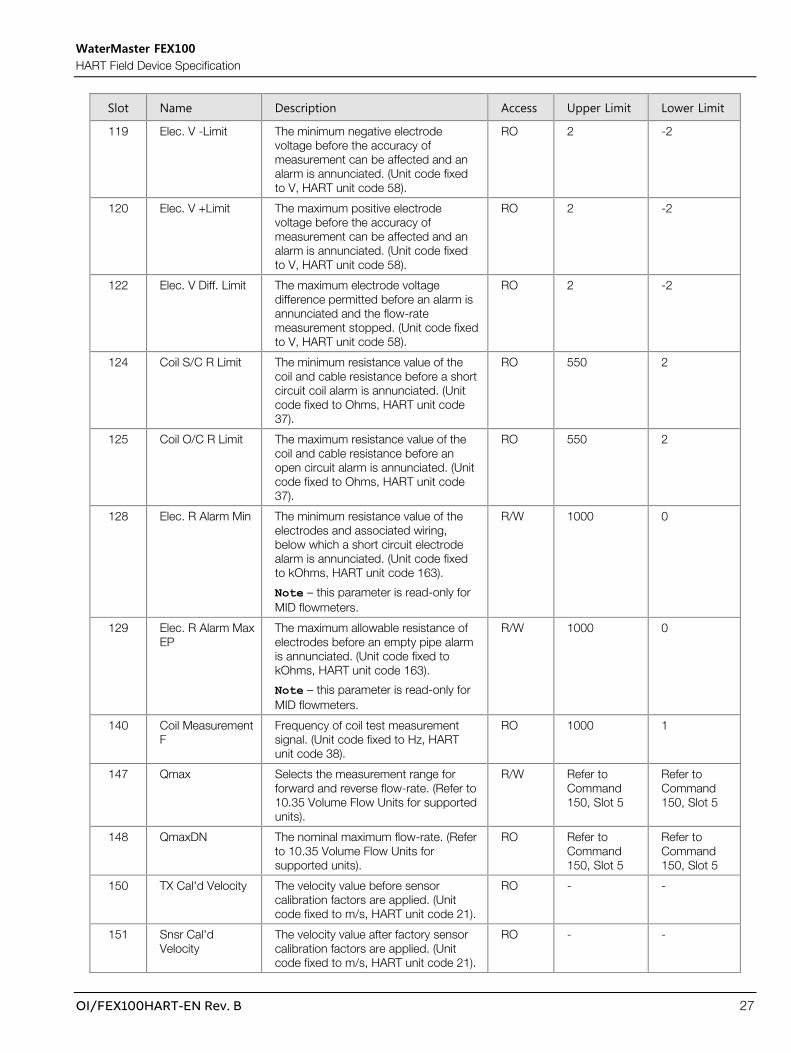
OI/FEX100HART-EN Rev. B 27
Slot Name Description Access Upper Limit Lower Limit
119 Elec. V -Limit The minimum negative electrode voltage before the accuracy of measurement can be affected and an alarm is annunciated. (Unit code fixed to V, HART unit code 58).
RO 2 -2
120 Elec. V +Limit The maximum positive electrode voltage before the accuracy of measurement can be affected and an alarm is annunciated. (Unit code fixed to V, HART unit code 58).
RO 2 -2
122 Elec. V Diff. Limit The maximum electrode voltage difference permitted before an alarm is annunciated and the flow-rate measurement stopped. (Unit code fixed to V, HART unit code 58).
RO 2 -2
124 Coil S/C R Limit The minimum resistance value of the coil and cable resistance before a short circuit coil alarm is annunciated. (Unit code fixed to Ohms, HART unit code 37).
RO 550 2
125 Coil O/C R Limit The maximum resistance value of the coil and cable resistance before an open circuit alarm is annunciated. (Unit code fixed to Ohms, HART unit code 37).
RO 550 2
128 Elec. R Alarm Min The minimum resistance value of the electrodes and associated wiring, below which a short circuit electrode alarm is annunciated. (Unit code fixed to kOhms, HART unit code 163).
Note – this parameter is read-only for MID flowmeters.
R/W 1000 0
129 Elec. R Alarm Max EP
The maximum allowable resistance of electrodes before an empty pipe alarm is annunciated. (Unit code fixed to kOhms, HART unit code 163).
Note – this parameter is read-only for MID flowmeters.
R/W 1000 0
140 Coil Measurement F
Frequency of coil test measurement signal. (Unit code fixed to Hz, HART unit code 38).
RO 1000 1
147 Qmax Selects the measurement range for forward and reverse flow-rate. (Refer to 10.35 Volume Flow Units for supported units).
R/W Refer to Command 150, Slot 5
Refer to Command 150, Slot 5
148 QmaxDN The nominal maximum flow-rate. (Refer to 10.35 Volume Flow Units for supported units).
RO Refer to Command 150, Slot 5
Refer to Command 150, Slot 5
150 TX Cal'd Velocity The velocity value before sensor calibration factors are applied. (Unit code fixed to m/s, HART unit code 21).
RO - -
151 Snsr Cal'd Velocity
The velocity value after factory sensor calibration factors are applied. (Unit code fixed to m/s, HART unit code 21).
RO - -

WaterMaster FEX100 HART Field Device Specification
28 OI/FEX100HART-EN Rev. B
Slot Name Description Access Upper Limit Lower Limit
152 Snsr User Velocity The velocity value after user calibration factors are applied. (Unit code fixed to m/s, HART unit code 21).
RO - -
153 Velocity The final output flow velocity value. (Refer to 10.34 Velocity Units for supported units).
RO - -
154 Volume Flowrate The output volume flow value. (Refer to 10.35 Volume Flow Units for supported units).
RO - -
155 Q % The volume flow-rate expressed as a percentage of Qmax. (Unit code fixed to %, HART unit code 57).
RO - -
157 Simulation Velocity
Fixed velocity value to output. (Refer to 10.34 Velocity Units for supported units).
Note – this parameter is read-only for MID flowmeters.
R/W Refer to Command 150, Slot 2
Refer to Command 150, Slot 2
158 Simulation Q Fixed volume flow-rate to output. (Refer to 10.35 Volume Flow Units for supported units).
Note – this parameter is read-only for MID flowmeters.
R/W Refer to Command 150, Slot 4
Refer to Command 150, Slot 4
159 Simulation Q% Fixed value of Flow % to output. (Unit code fixed to %, HART unit code 57).
Note – this parameter is read-only for MID flowmeters.
R/W 200 -200
160 TX Zero Zero velocity correction factor being applied. (Unit code fixed to mm/s, manufacturer specific unit code 240).
RO 50 -50
161 TX Span Span velocity correction factor being applied. (Unit code fixed to %, HART unit code 57).
RO 120 80
162 Zero Sz Factory set sensor zero velocity factor. (Unit code fixed to mm/s, manufacturer specific unit code 240).
RO 50 -50
163 Span Ss Factory set sensor span factor. (Unit code fixed to %, HART unit code 57).
RO 500 -500
164 Trim St Trim calibration factor being applied. (Unit code fixed to %, HART unit code 57).
RO 50 -50
166 QmaxDN (Special) QmaxDN value for special sensor sizes. (Refer to 10.35 Volume Flow Units for supported units).
R/W 100000 0
167 Special Size (Bore)
Special sensor bore. (Unit code fixed to mm, HART unit code 49).
RO 5000 1
168 User Zero User Zero value. (Unit code fixed to mm/s, manufacturer specific unit code 240).
Note – this parameter is read-only for MID flowmeters.
R/W 50 -50

WaterMaster FEX100 HART Field Device Specification
OI/FEX100HART-EN Rev. B 29
Slot Name Description Access Upper Limit Lower Limit
169 User Span User Span value. (Unit code fixed to %, HART unit code 57).
Note – this parameter is read-only for MID flowmeters.
R/W 250 -250
171 Damping System damping value. (Unit code fixed to s, HART unit code 51).
R/W 60 0.02
172 Factory Cutoff Factory cutoff level velocity. (Unit code fixed to mm/s, manufacturer specific unit code 240).
RO 50 0
173 Flow Cutoff Level User flow cutoff percentage of Qmax. (Unit code fixed to %, HART unit code 57).
Note – this parameter is read-only for MID flowmeters.
R/W 10 0
174 Hysteresis User hysteresis value for flow cutoff level. (Unit code fixed to %, HART unit code 57).
Note – this parameter is read-only for MID flowmeters.
R/W 50 0
175 Flowrate Limits Min. Alarm
Minimum percentage of Qmax before low flow alarm. (Unit code fixed to %, HART unit code 57).
R/W 130 0
176 Flowrate Limits Max. Alarm
Maximum percentage of Qmax before high flow alarm. (Unit code fixed to %, HART unit code 57).
R/W 130 0
185 Probe Pipe Bore Bore of the pipe in use with probe type sensor. (Unit code fixed to mm, HART unit code 49).
R/W 5000 1
188 Sensor L Shift Shift in sensor inductance. (Unit code fixed to %, HART unit code 57).
RO 100 -100
190 Volume Forward Volume forward totalizer in single-precision floating point format. (Refer to 10.37 Volume Totalizer Units for supported units).
RO - -
191 Volume Reverse Volume reverse totalizer in single-precision floating point format. (Refer to 10.37 Volume Totalizer Units for supported units).
RO - -
192 Volume Net Volume net totalizer in single-precision floating point format. (Refer to 10.37 Volume Totalizer Units for supported units).
RO - -

WaterMaster FEX100 HART Field Device Specification
30 OI/FEX100HART-EN Rev. B
9.6 Command #134: Read Single-Precision Floating-Point Reads a variable in single-precision floating-point format.
Request Data Bytes
Byte Format Description
0 Byte Slot number of the variable to read.
Response Data Bytes
Byte Format Description
0 Byte Slot number of the requested variable.
1-4 Single-Precision Floating-Point
Value of the requested variable.
Command-Specific Response Codes
Code Class Description
0 Success No Command-Specific Errors.
2 Failure Invalid Selection.
5 Failure Too Few Data Bytes Received.

WaterMaster FEX100 HART Field Device Specification
OI/FEX100HART-EN Rev. B 31
9.7 Command #135: Write Single-Precision Floating-Point Writes the value to a variable in single-precision floating-point format.
Request Data Bytes
Byte Format Description
0 Byte Slot number of the variable to write.
1-4 Single-Precision Floating-Point
Value to write to the variable.
Response Data Bytes
Byte Format Description
0 Byte Slot number of the requested variable.
1-4 Single-Precision Floating-Point
Value of the requested variable.
Command-Specific Response Codes
Code Class Description
0 Success No Command-Specific Errors.
2 Failure Invalid Selection.
3 Failure Passed Parameter Too Large.
4 Failure Passed Parameter Too Small.
5 Failure Too Few Data Bytes Received.
7 Failure In Write Protect Mode.
16 Failure Access Restricted.
Command 134/135 Slot Content
Slot Name Description Access Upper Limit Lower Limit
0 Pulse Factor Pulse Factor parameter for Digital Outputs 1 & 2.
R/W 10000000 0.00001
16 Insertion Factor Insertion Factor for probe type sensors. R/W 3.0 1.0
17 Profile Factor Profile Factor for probe type sensors. R/W 3.0 1.0

WaterMaster FEX100 HART Field Device Specification
32 OI/FEX100HART-EN Rev. B
9.8 Command #136: Read String Reads a twenty-character string.
Request Data Bytes
Byte Format Description
0 Byte Slot number of the string to read.
Response Data Bytes
Byte Format Description
0 Byte Slot number of the requested variable.
1-21 Byte Value of the requested string variable.
Command-Specific Response Codes
Code Class Description
0 Success No Command-Specific Errors.
2 Failure Invalid Selection.
5 Failure Too Few Data Bytes Received.

WaterMaster FEX100 HART Field Device Specification
OI/FEX100HART-EN Rev. B 33
9.9 Command #137: Write String Writes a twenty-character string.
Request Data Bytes
Byte Format Description
0 Byte Slot number of the string to read.
1-21 Byte String data to write.
Response Data Bytes
Byte Format Description
0 Byte Slot number of the requested variable.
1-21 Byte Value of the requested string variable.
Command-Specific Response Codes
Code Class Description
0 Success No Command-Specific Errors.
2 Failure Invalid Selection.
5 Failure Too Few Data Bytes Received.
7 Failure In Write Protect Mode.
16 Failure Access Restricted.

WaterMaster FEX100 HART Field Device Specification
34 OI/FEX100HART-EN Rev. B
Command 136/137 Slot Content
Slot Name Description Access
0 TX Version Application Transmitter firmware version number. RO
1 TX Version Bootloader Transmitter bootloader firmware version number. RO
2 TX Run Hours Run-hours counter of the transmitter. RO
3 Sensor Run Hours Run-hours counter of the sensor. RO
4 TX Calibration First Cal. Date Date of initial transmitter calibration. RO
5 TX Calibration Last Cal. Date Date of the most recent transmitter calibration. RO
6 Sensor Calibration First Cal. Date
Date of initial sensor calibration. RO
7 Sensor Calibration Last Cal. Date
Date of the most recent sensor calibration. RO
8 Application CRC CRC value of the application firmware. RO
9 Manufacturer Address 1 First line of the manufacturer address. RO
10 Manufacturer Address 2 Second line of the manufacturer address. RO
11 Manufacturer Contact Contact details for the manufacturer. RO
12 Transmitter TAG User defined transmitter descriptive text. R/W
13 Transmitter SAP/ERP Number Manufacturer assigned transmitter SAP/ERP number. RO
16 TX Version H/W Hardware version code of the transmitter hardware. RO
17 Sensor TAG User defined sensor descriptive text. R/W
18 Sensor Calibration Certificate Number
Calibration facility assigned certificate number. RO
19 Sensor SAP/ERP Number Manufacturer assigned sensor SAP/ERP number. RO
21 Transmitter Location String User defined text to describe the transmitter installation details. R/W
22 Sensor Location String User defined text to describe the sensor installation details. R/W
23 Manufacturer Name of the transmitter manufacturer. RO
24 HART F/W Version number of the HART modem firmware. RO
25 Term Board S/W Version number of the remote sensor memory firmware. RO

WaterMaster FEX100 HART Field Device Specification
OI/FEX100HART-EN Rev. B 35
9.10 Command #138: Read Double-Precision Floating-Point with Unit Reads a variable in double-precision floating-point format with its associated unit code.
Request Data Bytes
Byte Format Description
0 Byte Slot number of the variable to read.
Response Data Bytes
Byte Format Description
0 Byte Slot number of the requested variable.
1 Byte The requested variable associated unit code.
2-9 Double-Precision Floating-Point
The requested variable value.
Command-Specific Response Codes
Code Class Description
0 Success No Command-Specific Errors.
2 Failure Invalid Selection.
5 Failure Too Few Data Bytes Received.
Command 138 Slot Content
Slot Name Description Access
0 Volume Forward Forward volume totalizer in double-precision floating-point format. (Refer to 10.37 Volume Totalizer Units for supported units).
RO
1 Volume Reverse Reverse volume totalizer in double-precision floating-point format. (Refer to 10.37 Volume Totalizer Units for supported units).
RO
2 Volume Net Net volume totalizer in double-precision floating- point format. (Refer to 10.37 Volume Totalizer Units for supported units).
RO

WaterMaster FEX100 HART Field Device Specification
36 OI/FEX100HART-EN Rev. B
9.11 Command #143: Trigger Action Triggers a transmitter action.
Request Data Bytes
Byte Format Description
0 Byte Slot number of the action to trigger.
1 Byte Dummy write value.
Response Data Bytes
Byte Format Description
0 Byte Slot number of the requested action.
1 Byte Echo of dummy write value.
Command-Specific Response Codes
Code Class Description
0 Success No Command-Specific Errors.
2 Failure Invalid Selection.
5 Failure Too Few Data Bytes Received.
7 Failure In Write Protect Mode.
16 Failure Access Restricted.
Command 143 Slot Content
Slot Name Description
5 Clear Alarm History Clears the process alarm history in the transmitter.
Note – this parameter is read-only for MID flowmeters.
13 Reset Totalizer All Volume
Resets all volume totalizers.
Note – this parameter is read-only for MID flowmeters.
14 Reset Totalizer Volume FWD
Resets the forward volume totalizer.
Note – this parameter is read-only for MID flowmeters.
15 Reset Totalizer Volume REV
Resets the reverse volume totalizer.
Note – this parameter is read-only for MID flowmeters.
16 Reset Totalizer Volume NET
Resets the net volume totalizer.
Note – this parameter is read-only for MID flowmeters.
20 User Defaults Restore
Restores factory set default values and ROM based default values where these are unavailable to installation type data.
Note – this parameter is read-only for MID flowmeters.
WaterMaster FEX100 HART Field Device Specification
OI/FEX100HART-EN Rev. B 37
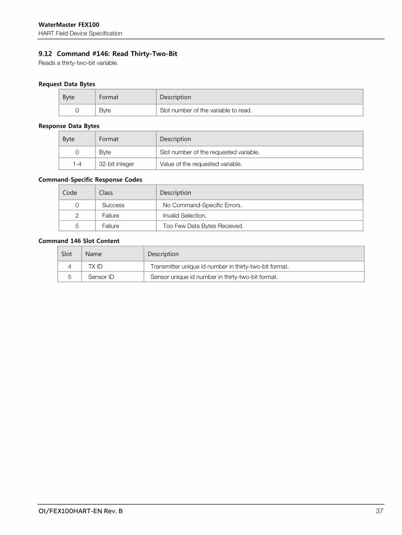
9.12 Command #146: Read Thirty-Two-Bit Reads a thirty-two-bit variable.
Request Data Bytes
Byte Format Description
0 Byte Slot number of the variable to read.
Response Data Bytes
Byte Format Description
0 Byte Slot number of the requested variable.
1-4 32-bit integer Value of the requested variable.
Command-Specific Response Codes
Code Class Description
0 Success No Command-Specific Errors.
2 Failure Invalid Selection.
5 Failure Too Few Data Bytes Received.
Command 146 Slot Content
Slot Name Description
4 TX ID Transmitter unique id number in thirty-two-bit format.
5 Sensor ID Sensor unique id number in thirty-two-bit format.

WaterMaster FEX100 HART Field Device Specification
38 OI/FEX100HART-EN Rev. B
9.13 Command #148: Read Twenty-Four-Bit Id Reads a device identifier in HART format (24-bit).
Request Data Bytes
Byte Format Description
0 Byte Slot number of the id to read.
Response Data Bytes
Byte Format Description
0 Byte Slot number of the requested id.
1-3 Byte Value of the requested device id.
Command-Specific Response Codes
Code Class Description
0 Success No Command-Specific Errors.
2 Failure Invalid Selection.
5 Failure Too Few Data Bytes Received.
Command 148 Slot Content
Slot Name Description
0 TX ID Unique Transmitter id number in twenty-four-bit format.
1 Sensor ID Unique Sensor id number in twenty-four-bit format.

WaterMaster FEX100 HART Field Device Specification
OI/FEX100HART-EN Rev. B 39
9.14 Command #150: Read Dynamic Single-Precision Floating-Point Range Reads single-precision floating-point based dynamic ranges associated with other parameters.
Request Data Bytes
Byte Format Description
0 Byte Slot number of the range item to read.
Response Data Bytes
Byte Format Description
0 Byte Slot number of the requested range item.
1-4 Single-Precision Floating-Point
The upper range value of the requested item.
5-8 Single-Precision Floating-Point
The lower range value of the requested item.
Command-Specific Response Codes
Code Class Description
0 Success No Command-Specific Errors.
2 Failure Invalid Selection.
5 Failure Too Few Data Bytes Received.
Command 150 Slot Content
Slot Name Description
0 Fixed Current Output Range of Current Output values that can be simulated.
1 Digital Output Limit Frequency Range of the Digital Output Limit Frequency parameter.
2 Simulated Velocity Limits Range of velocity simulation values.
3 Velocity Limits Range of velocity values.
4 Simulated Flowrate Range of flowrate simulation values.
5 Flowrate Range of flowrate values.

WaterMaster FEX100 HART Field Device Specification
40 OI/FEX100HART-EN Rev. B
9.15 Command #180: Trigger Adjust Function Triggers a calibration adjustment function.
Request Data Bytes
Byte Format Description
0 Byte Slot number of the adjust function to trigger.
1 Byte Dummy write value.
Response Data Bytes
Byte Format Description
0 Byte Slot number of the requested adjust function.
1 Byte Echo of dummy write variable.
Command-Specific Response Codes
Code Class Description
0 Success No Command-Specific Errors.
2 Failure Invalid Selection.
5 Failure Too Few Data Bytes Received.
7 Failure In Write Protect Mode.
16 Failure Access Restricted.
114 Failure Access Restricted – Action Not Available.
Command 180 Slot Content
Slot Name Description
2 User Zero Adjust Starts adjustment of the User Zero.
Note – this parameter is read-only for MID flowmeters.
WaterMaster FEX100 HART Field Device Specification
OI/FEX100HART-EN Rev. B 41
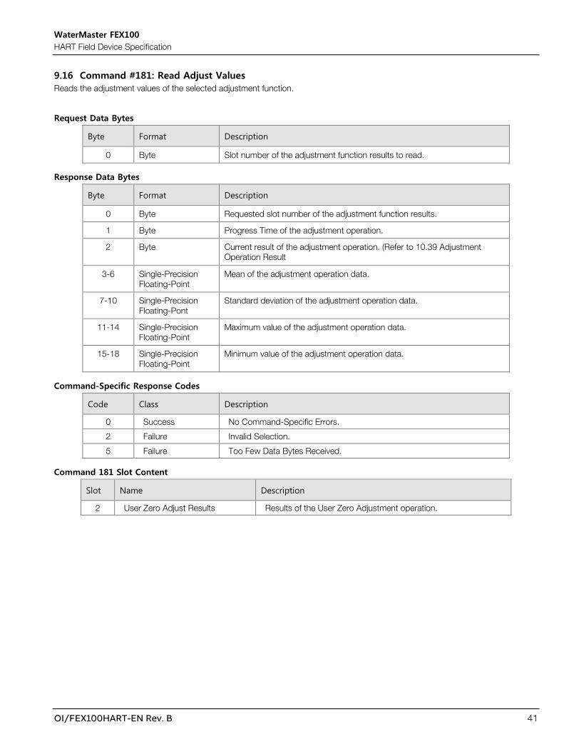
9.16 Command #181: Read Adjust Values Reads the adjustment values of the selected adjustment function.
Request Data Bytes
Byte Format Description
0 Byte Slot number of the adjustment function results to read.
Response Data Bytes
Byte Format Description
0 Byte Requested slot number of the adjustment function results.
1 Byte Progress Time of the adjustment operation.
2 Byte Current result of the adjustment operation. (Refer to 10.39 Adjustment Operation Result
3-6 Single-Precision Floating-Point
Mean of the adjustment operation data.
7-10 Single-Precision Floating-Pont
Standard deviation of the adjustment operation data.
11-14 Single-Precision Floating-Point
Maximum value of the adjustment operation data.
15-18 Single-Precision Floating-Point
Minimum value of the adjustment operation data.
Command-Specific Response Codes
Code Class Description
0 Success No Command-Specific Errors.
2 Failure Invalid Selection.
5 Failure Too Few Data Bytes Received.
Command 181 Slot Content
Slot Name Description
2 User Zero Adjust Results Results of the User Zero Adjustment operation.

WaterMaster FEX100 HART Field Device Specification
42 OI/FEX100HART-EN Rev. B
9.17 Command #182: Read Additional Diagnostic Information Reads information pertaining to transmitter alarms.
Request Data Bytes
Byte Format Description
0 Byte Slot number of the alarm to read additional information for.
Response Data Bytes
Byte Format Description
0 Byte Requested slot number of the alarm additional information is requested for.
1-2 16-bit integer Number of times the alarm has occurred.
3-6 32-bit integer Total number of milliseconds for which the alarm has been active.
7-8 16-bit integer Total number of days for which the alarm has been active.
9-12 32-bit integer Number of milliseconds since the last alarm instance.
13-14 16-bit integer Number of days since the last alarm instance.
Command-Specific Response Codes
Code Class Description
0 Success No Command-Specific Errors.
2 Failure Invalid Selection.
5 Failure Too Few Data Bytes Received.
WaterMaster FEX100 HART Field Device Specification
OI/FEX100HART-EN Rev. B 43
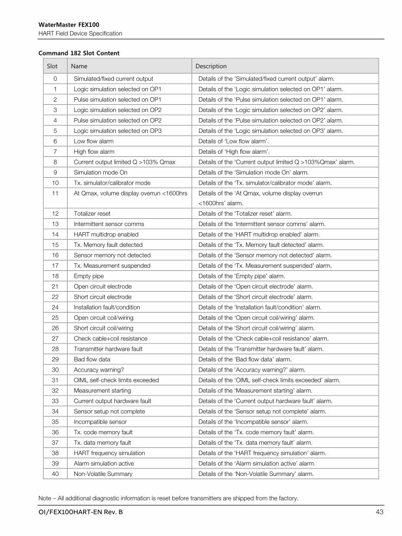
Command 182 Slot Content
Slot Name Description
0 Simulated/fixed current output Details of the ‘Simulated/fixed current output’ alarm.
1 Logic simulation selected on OP1 Details of the ‘Logic simulation selected on OP1’ alarm.
2 Pulse simulation selected on OP1 Details of the ‘Pulse simulation selected on OP1’ alarm.
3 Logic simulation selected on OP2 Details of the ‘Logic simulation selected on OP2’ alarm.
4 Pulse simulation selected on OP2 Details of the ‘Pulse simulation selected on OP2’ alarm.
5 Logic simulation selected on OP3 Details of the ‘Logic simulation selected on OP3’ alarm.
6 Low flow alarm Details of ‘Low flow alarm’.
7 High flow alarm Details of ‘High flow alarm’.
8 Current output limited Q >103% Qmax Details of the ‘Current output limited Q >103%Qmax’ alarm.
9 Simulation mode On Details of the ‘Simulation mode On’ alarm.
10 Tx. simulator/calibrator mode Details of the ‘Tx. simulator/calibrator mode’ alarm.
11 At Qmax, volume display overrun <1600hrs Details of the ‘At Qmax, volume display overrun
<1600hrs’ alarm.
12 Totalizer reset Details of the ‘Totalizer reset’ alarm.
13 Intermittent sensor comms Details of the ‘Intermittent sensor comms’ alarm.
14 HART multidrop enabled Details of the ‘HART multidrop enabled’ alarm.
15 Tx. Memory fault detected Details of the ‘Tx. Memory fault detected’ alarm.
16 Sensor memory not detected Details of the ‘Sensor memory not detected’ alarm.
17 Tx. Measurement suspended Details of the ‘Tx. Measurement suspended’ alarm.
18 Empty pipe Details of the ‘Empty pipe’ alarm.
21 Open circuit electrode Details of the ‘Open circuit electrode’ alarm.
22 Short circuit electrode Details of the ‘Short circuit electrode’ alarm.
24 Installation fault/condition Details of the ‘Installation fault/condition’ alarm.
25 Open circuit coil/wiring Details of the ‘Open circuit coil/wiring’ alarm.
26 Short circuit coil/wiring Details of the ‘Short circuit coil/wiring’ alarm.
27 Check cable+coil resistance Details of the ‘Check cable+coil resistance’ alarm.
28 Transmitter hardware fault Details of the ‘Transmitter hardware fault’ alarm.
29 Bad flow data Details of the ‘Bad flow data’ alarm.
30 Accuracy warning? Details of the ‘Accuracy warning?’ alarm.
31 OIML self-check limits exceeded Details of the ‘OIML self-check limits exceeded’ alarm.
32 Measurement starting Details of the ‘Measurement starting’ alarm.
33 Current output hardware fault Details of the ‘Current output hardware fault’ alarm.
34 Sensor setup not complete Details of the ‘Sensor setup not complete’ alarm.
35 Incompatible sensor Details of the ‘Incompatible sensor’ alarm.
36 Tx. code memory fault Details of the ‘Tx. code memory fault’ alarm.
37 Tx. data memory fault Details of the ‘Tx. data memory fault’ alarm.
38 HART frequency simulation Details of the ‘HART frequency simulation’ alarm.
39 Alarm simulation active Details of the ‘Alarm simulation active’ alarm.
40 Non-Volatile Summary Details of the ‘Non-Volatile Summary’ alarm.
Note – All additional diagnostic information is reset before transmitters are shipped from the factory.

WaterMaster FEX100 HART Field Device Specification
44 OI/FEX100HART-EN Rev. B
10. Tables
10.1 Security Mode
0 High Security Disabled
1 High Security Enabled
10.2 Current Output Alarm Selection
0 High Alarm
1 Low Alarm
2 Off
10.3 Current Output Mode
0 4 .. 20mA
1 4 .. 12 .. 20mA
2 4 .. 20 mA FWD/REV
10.4 Enable State
0 Disabled
1 Enabled
10.5 Simulation Mode
0 Off
1 Flow Velocity
2 Q
3 Q%
4 Iout
5 Pulse 1
6 Pulse 2
7 Logic 1
8 Logic 2
9 Logic 3
Note – Flow Velocity, Q and Q% are not available for MID flowmeters.
10.6 Device Calibration Location

WaterMaster FEX100 HART Field Device Specification
OI/FEX100HART-EN Rev. B 45
0 Stonehouse
1 Goettingen
2 Warminster
3 Moorebank
4 Shanghai
5 Burlington
6 Not Specified
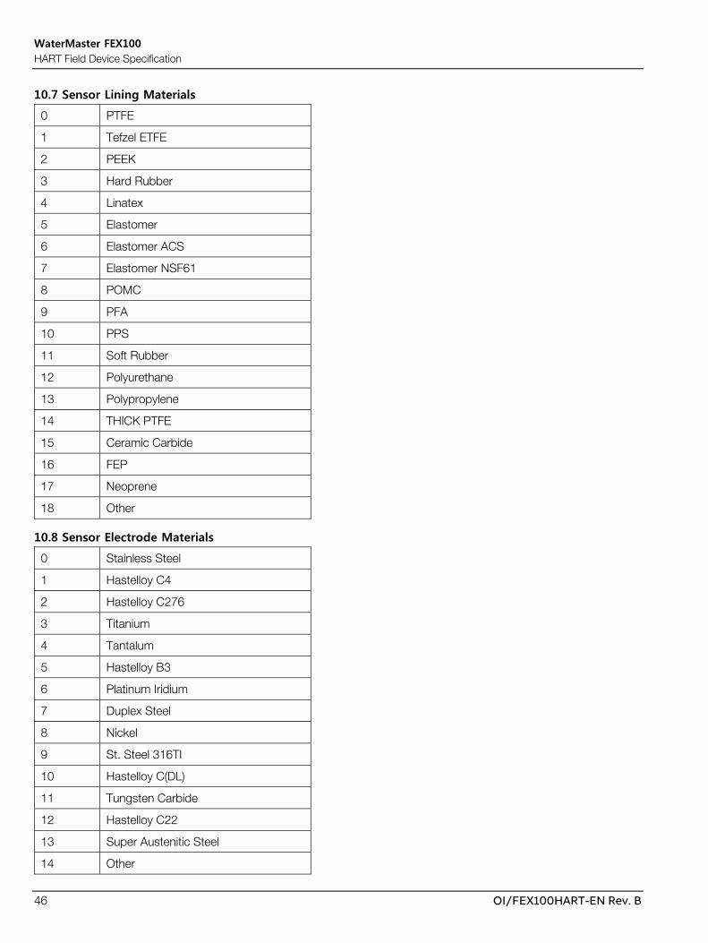
WaterMaster FEX100 HART Field Device Specification
46 OI/FEX100HART-EN Rev. B
10.7 Sensor Lining Materials
0 PTFE
1 Tefzel ETFE
2 PEEK
3 Hard Rubber
4 Linatex
5 Elastomer
6 Elastomer ACS
7 Elastomer NSF61
8 POMC
9 PFA
10 PPS
11 Soft Rubber
12 Polyurethane
13 Polypropylene
14 THICK PTFE
15 Ceramic Carbide
16 FEP
17 Neoprene
18 Other
10.8 Sensor Electrode Materials
0 Stainless Steel
1 Hastelloy C4
2 Hastelloy C276
3 Titanium
4 Tantalum
5 Hastelloy B3
6 Platinum Iridium
7 Duplex Steel
8 Nickel
9 St. Steel 316TI
10 Hastelloy C(DL)
11 Tungsten Carbide
12 Hastelloy C22
13 Super Austenitic Steel
14 Other
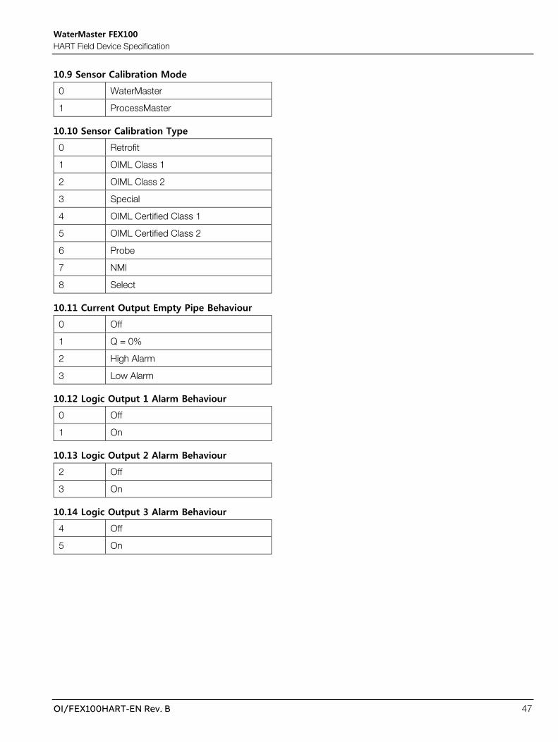
WaterMaster FEX100 HART Field Device Specification
OI/FEX100HART-EN Rev. B 47
10.9 Sensor Calibration Mode
0 WaterMaster
1 ProcessMaster
10.10 Sensor Calibration Type
0 Retrofit
1 OIML Class 1
2 OIML Class 2
3 Special
4 OIML Certified Class 1
5 OIML Certified Class 2
6 Probe
7 NMI
8 Select
10.11 Current Output Empty Pipe Behaviour
0 Off
1 Q = 0%
2 High Alarm
3 Low Alarm
10.12 Logic Output 1 Alarm Behaviour
0 Off
1 On
10.13 Logic Output 2 Alarm Behaviour
2 Off
3 On
10.14 Logic Output 3 Alarm Behaviour
4 Off
5 On

WaterMaster FEX100 HART Field Device Specification
48 OI/FEX100HART-EN Rev. B
10.15 Diagnostic Alarm Simulation

WaterMaster FEX100 HART Field Device Specification
OI/FEX100HART-EN Rev. B 49
0 None
1 Iout Simulated
2 Logic OP1 Simulated
3 Pulse OP1 Simulated
4 Logic OP2 Simulated
5 Pulse OP2 Simulated
6 Logic OP3 Simulated
7 Min Flow Value
8 Max Flow Value
9 103% Reached
10 Simulated Flow
11 Calibrator
12 Display Overrange
13 Totalizer Reset
14 Poor Sensor Comms
15 Address Not Zero
16 TX Memory Fail
17 No Sensor
18 Measurement Offline
19 Empty Pipe
20 Elec. Open Circuit
21 Elec. Short Circuit
22 Installation Fault
23 Coil Open Circuit
24 Coil Short Circuit
25 Loop Resistance
26 TX Hardware
27 Bad Flow Data
28 Electrode Voltage
29 OIML Self Check
30 Measurement Starting
31 Iout Hardware Fault
32 Not Calibrated
33 Calibration Mismatch
34 ROM Error
35 RAM Error

WaterMaster FEX100 HART Field Device Specification
50 OI/FEX100HART-EN Rev. B
36 HART Simulation
37 NV Summary Alarm
10.16 Logic Output Simulation
0 Off
1 On
10.17 Logic Output State
0 Open
1 Closed
10.18 Logic Output Signal Source
0 No Logic Source
1 Forward/Reverse Flow
2 Digital Output Alarm
10.19 Logic Output Action State
0 Normally Open
1 Normally Closed
10.20 Digital Output Function
0 Pulse F/Pulse R
1 Pulse F/Logic
2 Pulse FR/Logic
3 Logic/Logic
10.21 Digital Output Pulse Mode
0 Pulse / Unit
1 Fullscale Frequency
10.22 Language
0 English
1 German
2 French
3 Spanish
4 Italian
9 Polish

WaterMaster FEX100 HART Field Device Specification
OI/FEX100HART-EN Rev. B 51
10.23 Operator Page Line Items
0 Volume Flowrate
1 Q%
2 Current Out
3 Velocity
4 Volume Forward
5 Volume Reverse
6 Volume Net
10.24 Operator Page 1 Display Modes
5 1 x 6
6 1 x 6 + Bargraph
7 1 x 9
8 1 x 9 + Bargraph
9 2 x 9
10 2 x 9 + Bargraph
11 3 x 9
10.25 Operator Pages 2 & 3 Display Modes
0 Off
5 1 x 6
6 1 x 6 + Bargraph
7 1 x 9
8 1 x 9 + Bargraph
9 2 x 9
10 2 x 9 + Bargraph
11 3 x 9
10.26 Display Decimal Point Settings
0 x
1 x.x
2 x.xx
3 x.xxx
4 x.xxxx
5 x.xxxxx
10.27 Display Date Formats

WaterMaster FEX100 HART Field Device Specification
52 OI/FEX100HART-EN Rev. B
0 DD-MM-YYYY
1 MM-DD-YYYY
2 YYYY-MM-DD

WaterMaster FEX100 HART Field Device Specification
OI/FEX100HART-EN Rev. B 53
10.28 Mains Frequency
50 50Hz
60 60Hz
10.29 Drive Mode
0 User
1 1
2 2
3 3
4 4
5 5
6 6
7 7
8 8
9 3A
10 4A
11 5A
12 5B
13 6A
14 6B
15 7A
16 7B
17 7C
18 7D
19 8A
20 8B
21 8C
10.30 Sensor Type

WaterMaster FEX100 HART Field Device Specification
54 OI/FEX100HART-EN Rev. B
0 Probe
1 Process
2 Hygienic
3 WM Reduced Throat
4 WM Full Bore
5 DE4
6 DE2
7 Process OIML
8 Hygienic OIML
9 No Sensor
10.31 Sensor Bore Size
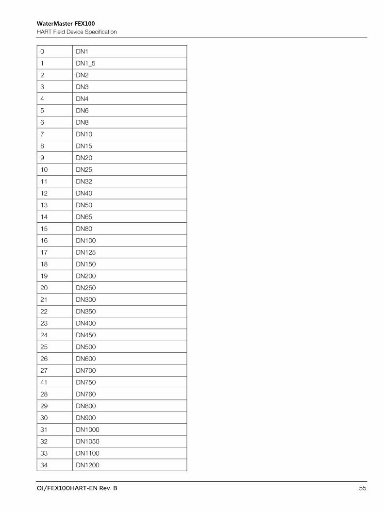
WaterMaster FEX100 HART Field Device Specification
OI/FEX100HART-EN Rev. B 55
0 DN1
1 DN1_5
2 DN2
3 DN3
4 DN4
5 DN6
6 DN8
7 DN10
8 DN15
9 DN20
10 DN25
11 DN32
12 DN40
13 DN50
14 DN65
15 DN80
16 DN100
17 DN125
18 DN150
19 DN200
20 DN250
21 DN300
22 DN350
23 DN400
24 DN450
25 DN500
26 DN600
27 DN700
41 DN750
28 DN760
29 DN800
30 DN900
31 DN1000
32 DN1050
33 DN1100
34 DN1200

WaterMaster FEX100 HART Field Device Specification
56 OI/FEX100HART-EN Rev. B
42 DN1350
35 DN1400
36 DN1500
37 DN1600
43 DN1650
38 DN1800
44 DN1950
39 DN2000
45 DN2100
46 DN2200
47 DN2400
40 Special
10.32 Flow Direction
0 Normal
1 Reversed
10.33 Meter Mode
0 Forward And Reverse
1 Forward Only
2 Reverse Only
10.34 Velocity Units
20 ft/s
21 m/s
114 in/s
115 in/min
116 ft/min

WaterMaster FEX100 HART Field Device Specification
OI/FEX100HART-EN Rev. B 57
10.35 Volume Flow Units
15 ft3/min
16 ugal/min
17 l/min
18 igal/min
19 m3/h
22 ugal/s
23 Mugal/d
24 l/s
25 Ml/d
26 ft3/s
27 ft3/d
28 m3/s
29 m3/d
30 igal/h
31 igal/d
130 ft3/h
131 m3/min
136 ugal/h
137 igal/s
138 l/h
235 ugal/d
241 bls/h
242 hl/h
243 kugal/min

WaterMaster FEX100 HART Field Device Specification
58 OI/FEX100HART-EN Rev. B
10.36 Service Port Baudrates
0 2400bps
1 4800bps
2 9600bps
3 19200bps
4 38400bps
10.37 Volume Totalizer Units
40 ugal
41 l
42 igal
43 m3
112 ft3
236 hl
244 kugal
245 ml
247 Ml
10.38 Read-Only Switch Status
0 Inactive
1 Active
10.39 Adjustment Operation Result
0 OK
15 Error
10.40 MID Meter Mode
0 Non-MID
1 MID Unlocked
2 MID Locked

WaterMaster FEX100 HART Field Device Specification
OI/FEX100HART-EN Rev. B 59
11. Unit Conversion The units used for internal values are shown below.
Measurement Internal Unit
Volume Flow l/s
Flow Velocity m/s
Volume l
To convert volume flow, velocity and totalizer values to other units, the following equation is used.
V2 = (V1 * cf1) * cf2
V2 Updated value
V1 Original value
cf1 Conversion factor to base units, from units of original value
cf2 Conversion factor from base units to units of updated flow value
To convert to base units from other units, the following equation is used.
V2 = V1 * cf1
V2 Value in base units
V1 Value in original unit
cf1 Conversion factor to base units

WaterMaster FEX100 HART Field Device Specification
60 OI/FEX100HART-EN Rev. B
11.1 Conversion factors for volume flow units from l/s
Unit Code Unit Conversion Factor
24 l/s 1
17 l/min 60
138 l/h 3600
242 hl/h 36
25 Ml/d 0.0864
28 m3/s 0.001
131 m3/min 0.06
19 m3/h 3.6
29 m3/d 86.4
26 ft3/s 0.03531467
15 ft3/min 2.1188802
130 ft3/h 127.132812
27 ft3/d 3051.187488
22 ugal/s 0.264172
16 ugal/min 15.85032
136 ugal/h 951.0192
235 ugal/d 22824.4608
23 Mugal/d 0.022824461
137 igal/s 0.2199688
18 igal/min 13.198128
30 igal/h 791.88768
31 igal/d 19005.30432
241 bls/h 30.6780444

WaterMaster FEX100 HART Field Device Specification
OI/FEX100HART-EN Rev. B 61
11.2 Conversion factors for volume flow units to l/s
Unit Code Unit Conversion Factor
24 l/s 1.00
17 l/min 0.016666667
138 l/h 0.000277778
242 hl/h 0.027777778
25 Ml/d 11.57407407
28 m3/s 1000
131 m3/min 16.66666667
19 m3/h 0.277777778
29 m3/d 0.011574074
26 ft3/s 28.31685
15 ft3/min 0.4719475
130 ft3/h 0.007865792
27 ft3/d 0.000327741
22 ugal/s 3.785413
16 ugal/min 0.063090217
136 ugal/h 0.001051504
235 ugal/d 0.0000438127
23 Mugal/d 43.81265046
137 igal/s 4.546099
18 igal/min 0.075768317
30 igal/h 0.001262805
31 igal/d 0.0000526169
241 bls/h 0.032596611

WaterMaster FEX100 HART Field Device Specification
62 OI/FEX100HART-EN Rev. B
11.3 Conversion factors for velocity units from m/s
Unit Code Unit Conversion Factor
21 m/s 1.00
114 in/s 39.370079
115 in/min 2362.20483
20 ft/s 3.28083992
116 ft/min 196.850403
11.4 Conversion factors for velocity units to m/s
Unit Code Unit Conversion Factor
21 m/s 1.00
114 in/s 0.0253999997
115 in/min 0.000423333317
20 ft/s 0.304800004
116 ft/min 0.00508000003
11.5 Conversion factors for volume units from l
Unit Code Unit Conversion Factor
43 m3 0.001
245 ml 1000
41 l 1
236 hl 0.00999999978
247 Ml 0.000000999999997
112 ft3 0.0353146717
42 igal 0.219968796
40 ugal 0.264171988
248 Mugal 0.000000264172002
246 bls 0.00852167886

WaterMaster FEX100 HART Field Device Specification
OI/FEX100HART-EN Rev. B 63
11.6 Conversion factors for volume units to l
Unit Code Unit Conversion Factor
43 m3 1000
245 ml 0.001
41 l 1
236 hl 100
247 Ml 1000000
112 ft3 28.3168507
42 igal 4.54609919
40 ugal 3.78541303
248 Mugal 3785413.0
246 bls 117.347801
Note – All conversion factors are represented as floating-point values used within application code.

WaterMaster FEX100 HART Field Device Specification
64 OI/FEX100HART-EN Rev. B
12. Performance
12.1 Sampling Rates Typical sampling rates are shown in the following table.
PV digital value calculation 10 per second
Analogue output update 20 per second
12.2 Power-Up On power up, the transmitter loads non-volatile data from the sensor and transmitter. For integral sensors this process takes approximately 2 seconds. For remote sensors, the slower serial communications between the transmitter and sensor increase this time to approximately 10 seconds.
During this period, the device will not respond to HART commands, and the analogue output is set to 0mA. After all non-volatile data is loaded, the system starts and can accept HART commands. The current output is set to 4mA until the first PV value is read.
Only after the Acquisition subsystem has completed initialisation will the first measurement be made, the PV value set, and the analogue output be set to a value representing the measurement. The slew rate of this movement is limited by the ‘Damping’ parameter.
Any alarms of class “Failure” occurring during power-up will force the PV to 0. Depending on its configuration, the analogue output will be set to either the “High Alarm” or “Low Alarm” value.
The device will still respond to HART commands during a fault condition.
12.3 Self-Test The self-test procedure is executed continuously during transmitter operation, with the following items being checked.
RAM
Program ROM
Configuration storage EEPROM
Transmitter calibration
12.4 Command Response Times
Minimum 85ms
Typical 110ms
Maximum 150ms
12.5 Busy and Delayed-Response The transmitter does not support the “device is busy” status.
Delayed-response is not used.
12.6 Long Messages The largest data field used in a command response is to Command 3, 33 (with the maximum number of variables being read) or 48 - 26 bytes including the two status bytes.

WaterMaster FEX100 HART Field Device Specification
OI/FEX100HART-EN Rev. B 65
12.7 Non-Volatile Memory EEPROM is used to hold the device’s configuration parameters. New data is written to this memory within 100ms of a write command.
12.8 Modes Fixed current mode is implemented, using Command 40. This mode is cleared by power loss, reset or setting a fixed current value of 0mA. Refer to Section 4.2.1 for details of current output operating modes during normal operation.
12.9 Write Protection Write-protection is provided, selected by an internal switch (see Section 4.3.2). When the switch is set to ‘ON’, no "write" or "action" commands are accepted. The switch status is read once only during transmitter power-up.
For MID meters, this switch only blocks access to MID related parameters. Non-MID related parameters are still writable. Refer to parameters MID Meter Mode and Sensor Cal. Type for determining the MID status of the Flowmeter.
12.10 Damping Damping is standard, affecting all process and device variables and the loop current signal.

WaterMaster FEX100 HART Field Device Specification
66 OI/FEX100HART-EN Rev. B
Annex A. Capability Checklist
Manufacturer, model and revision ABB FEX100 WaterMaster, rev. 0
Device type Transmitter
HART revision 5.7
Device Description available Yes
Number and type of sensors 1(integral or remote depending on transmitter model)
Number and type of host side signals 1: 4 - 20mA analogue
2: Digital Output 1 or Logic Output 1
3: Digital Output 2 or Logic Output 2
4: Logic Output 3
5: Infra-Red Service Port
Number of Device Variables 6
Number of Dynamic Variables 4
Mappable Dynamic Variables? No
Number of common-practice commands 8
Number of device-specific commands 17
Number of Slot Variables (Accessed via device-specific commands)
226
Bits of additional device status 38
Alternative operating modes? No
Burst mode? No
Write-protection? Yes
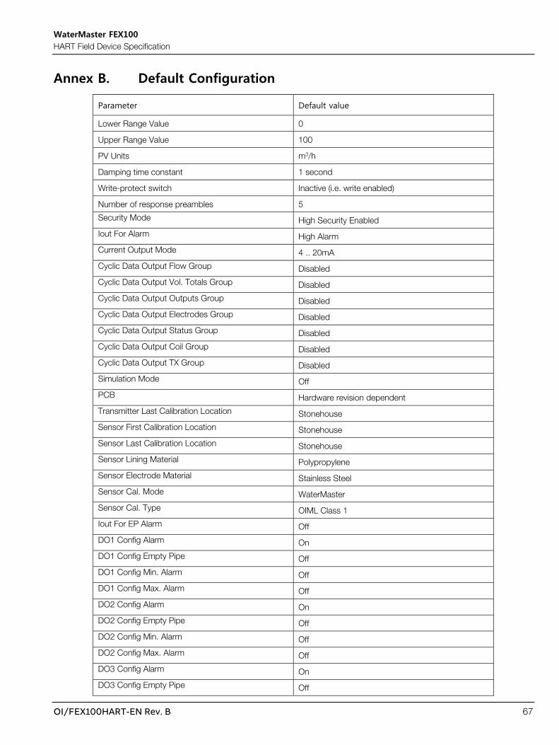
WaterMaster FEX100 HART Field Device Specification
OI/FEX100HART-EN Rev. B 67
Annex B. Default Configuration
Parameter Default value
Lower Range Value 0
Upper Range Value 100
PV Units m3/h
Damping time constant 1 second
Write-protect switch Inactive (i.e. write enabled)
Number of response preambles 5
Security Mode High Security Enabled
Iout For Alarm High Alarm
Current Output Mode 4 .. 20mA
Cyclic Data Output Flow Group Disabled
Cyclic Data Output Vol. Totals Group Disabled
Cyclic Data Output Outputs Group Disabled
Cyclic Data Output Electrodes Group Disabled
Cyclic Data Output Status Group Disabled
Cyclic Data Output Coil Group Disabled
Cyclic Data Output TX Group Disabled
Simulation Mode Off
PCB Hardware revision dependent
Transmitter Last Calibration Location Stonehouse
Sensor First Calibration Location Stonehouse
Sensor Last Calibration Location Stonehouse
Sensor Lining Material Polypropylene
Sensor Electrode Material Stainless Steel
Sensor Cal. Mode WaterMaster
Sensor Cal. Type OIML Class 1
Iout For EP Alarm Off
DO1 Config Alarm On
DO1 Config Empty Pipe Off
DO1 Config Min. Alarm Off
DO1 Config Max. Alarm Off
DO2 Config Alarm On
DO2 Config Empty Pipe Off
DO2 Config Min. Alarm Off
DO2 Config Max. Alarm Off
DO3 Config Alarm On
DO3 Config Empty Pipe Off

WaterMaster FEX100 HART Field Device Specification
68 OI/FEX100HART-EN Rev. B
Parameter Default value
DO3 Config Min. Alarm Off
DO3 Config Max. Alarm Off
Alarm Simulation None
Group Masking Check Function Off
Group Masking Off Specification Off
Group Masking Maintenance Off
Diagnostic Masking Overflow 103% On
Individual Masking Min. Alarm On
Individual Masking Max. Alarm On
Logic 1 Off
Logic 2 Off
Logic 3 Off
DO1 State Open
DO2 State Open
DO3 State Open
DO1 Logic No Logic Source
DO1 Action Normally Open
DO2 Logic No Logic Source
DO2 Action Normally Open
DO3 Logic No Logic Source
DO3 Action Normally Open
DO1/DO2 Function Pulse FR/Logic
Pulse Mode Pulse / Unit
Language English
Operator Page 1 1st Line Volume Flowrate
Operator Page 1 2nd Line Volume Flowrate
Operator Page 1 3rd Line Volume Flowrate
Operator Page 2 1st Line Volume Flowrate
Operator Page 2 2nd Line Volume Flowrate
Operator Page 2 3rd Line Volume Flowrate
Operator Page 3 1st Line Volume Flowrate
Operator Page 3 2nd Line Volume Flowrate
Operator Page 3 3rd Line Volume Flowrate
Contrast 50
Operator Page 1 Display Mode 1 x 6
Operator Page 2 Display Mode Off
Operator Page 3 Display Mode Off
Flowrate Format x.xx

WaterMaster FEX100 HART Field Device Specification
OI/FEX100HART-EN Rev. B 69
Parameter Default value
Volume Format x
Date / Time Format YYYY-MM-DD
Mains Frequency 50Hz
Drive Mode 5A
Sensor Type DE4
Sensor Size DN20
Flow Indication Normal
Fact. Cutoff No. Av. 4
Meter Mode Forward And Reverse
Velocity Unit m/s
Q (Flowrate) Unit m3/h
Max Baud Rate 38400bps
Volume & Pulse Unit m3
Read Only Switch Inactive
MID Meter Mode Non-MID
TX PIN 0
Current 0
Low Alarm Value 3.5
High Alarm Value 21.8
Iout 0
Pulse 1 / Pulse 2 0
DO1 Pulses 0
DO2 Pulses 0
Pulse Width 5
Limit Frequency 5250
Fullscale Frequency 5000
DC Back Off V 0
Coil L 0
Elec. R E1 0
Elec. R E2 0
TX Av. Gain Shift 0
Coil I Alarm Band 1
Excitation Current 100
Elec. V -Limit -1.5
Elec. V +Limit 1.8
Elec. V Diff. Limit 0.5
Coil S/C R Limit 5
Coil O/C R Limit 500

WaterMaster FEX100 HART Field Device Specification
70 OI/FEX100HART-EN Rev. B
Parameter Default value
Elec. R Alarm Min 0.1
Elec. R Alarm Max EP 200
Coil Measurement F 40
Qmax 2.5
QmaxDN 2.5
TX Cal'd Velocity 0
Snsr Cal'd Velocity 0
Snsr User Velocity 0
Velocity 0
Volume Flowrate 0
Q % 0
Simulation Velocity 0
Simulation Q 0
TX Zero 0
TX Span 100
Zero Sz 0
Span Ss 100
Trim St 0
QmaxDN (Special) 2.5
Special Size (Bore) 20
User Zero 0
User Span 100
Damping 1
Factory Cutoff 0
Flow Cutoff Level 0.5
Hysteresis 20
Min. Alarm 0
Max. Alarm 110
Probe Pipe Bore 250
Sensor L Shift 0
Volume Forward 0
Volume Reverse 0
Volume Net 0
Pulse Factor 50
Insertion Factor 1
Profile Factor 1

WaterMaster FEX100 HART Field Device Specification
OI/FEX100HART-EN Rev. B 71
Notes

WaterMaster FEX100 HART Field Device Specification
72 OI/FEX100HART-EN Rev. B
WaterMaster FEX100 HART Field Device Specification
OI/FEX100HART-EN Rev. B 73

Acknowledgments
• HART is a registered trademark of the FieldComm Group.• Modbus is a registered trademark of Schneider Electric USA Inc.• PROFIBUS is a registered trademark of PROFIBUS and
PROFINET International (PI).
Sales Service Software

OI/
FE
X10
0H
AR
T-E
N R
ev. B
10
.20
18
—We reserve the right to make technical changes or modify the contents of this document without prior notice. With regard to purchase orders, the agreed particulars shall prevail. ABB does not accept any responsibility whatsoever for potential errors or possible lack of information in this document.We reserve all rights in this document and in the subject matter and illustrations contained therein. Any reproduction, disclosure to third parties or utilization of its contents – in whole or in parts – is forbidden without prior written consent of ABB. © ABB 2018
—ABB Limited Measurement & Analytics Oldends Lane, Stonehouse Gloucestershire GL10 3TA UK Tel: +44 (0)1453 826661Fax: +44 (0)1453 829671 Email: [email protected] ABB Inc. Measurement & Analytics 125 E. County Line RoadWarminsterPA 18974USATel: +1 215 674 6000Fax: +1 215 674 7183
ABB Engineering (Shanghai) Ltd. Measurement & Analytics No. 4528, Kangxin Highway Pudong New District201319, ShanghaiP.R. ChinaTel: +86 (0) 21 6105 6666Fax: +86 (0) 21 6105 6677
abb.com/measurement