waterpilot fmx167 (ba) - shin-asystem.co.kr manual eng.pdf · waterpilot fmx167 table of contents...
TRANSCRIPT
BA231P/00/en/08.05
71003557
Operating Instructions
Waterpilot FMX167Level probe

Waterpilot FMX167
2 Endress+Hauser

Waterpilot FMX167 Table of contents
Endress+Hauser 3
Table of contents
1 Safety instructions . . . . . . . . . . . . . . . . 4
1.1 Designated use . . . . . . . . . . . . . . . . . . . . . . . . . . . . 4
1.2 Installation, commissioning and operation . . . . . . . . 4
1.3 Operational safety . . . . . . . . . . . . . . . . . . . . . . . . . . 4
1.4 Notes on safety conventions and icons . . . . . . . . . . . 5
2 Identification . . . . . . . . . . . . . . . . . . . . 6
2.1 Device designation . . . . . . . . . . . . . . . . . . . . . . . . . 6
2.2 Scope of supply . . . . . . . . . . . . . . . . . . . . . . . . . . . . 7
2.3 CE mark, declaration of conformity . . . . . . . . . . . . . 8
3 Installation . . . . . . . . . . . . . . . . . . . . . . 8
3.1 Incoming acceptance and storage . . . . . . . . . . . . . . . 8
3.2 Installation conditions . . . . . . . . . . . . . . . . . . . . . . . 9
3.3 Installation instructions . . . . . . . . . . . . . . . . . . . . . 10
3.4 Checking the installation . . . . . . . . . . . . . . . . . . . . 12
4 Wiring . . . . . . . . . . . . . . . . . . . . . . . . 13
4.1 Connecting the device . . . . . . . . . . . . . . . . . . . . . 13
4.2 Wiring up the measuring unit . . . . . . . . . . . . . . . . 16
4.3 Checking the wiring . . . . . . . . . . . . . . . . . . . . . . . 16
5 Operation . . . . . . . . . . . . . . . . . . . . . . 17
6 Maintenance. . . . . . . . . . . . . . . . . . . . 17
6.1 Exterior cleaning . . . . . . . . . . . . . . . . . . . . . . . . . . 17
7 Accessories . . . . . . . . . . . . . . . . . . . . 18
8 Trouble-shooting . . . . . . . . . . . . . . . . 20
8.1 Faults on Waterpilot FMX167 and
Waterpilot FMX167 with optional Pt 100 . . . . . . . 20
8.2 Faults of temperature transmitter TMT181 . . . . . . . 20
8.3 Spare Parts . . . . . . . . . . . . . . . . . . . . . . . . . . . . . . 21
9 Technical Data . . . . . . . . . . . . . . . . . . 21
Index . . . . . . . . . . . . . . . . . . . . . . . . . . . . . 22

Safety instructions Waterpilot FMX167
4 Endress+Hauser
1 Safety instructions
1.1 Designated use
The Waterpilot FMX167 is a hydrostatic pressure sensor for measuring the level of fresh water,
wastewater and seawater. Versions with a Pt 100 resistance thermometer can detect temperature
at the same time. The optional temperature transmitter converts the Pt 100 signal into a 420 mA
signal.
The manufacturer shall not accept any liability for damage arising from improper use or if the device
is used for purposes for which it was not intended.
1.2 Installation, commissioning and operation
The Waterpilot FMX167 and the temperature transmitter TMT181 (optional) are designed as fail-
safe to the state of the art and comply with prevailing regulations and EC directives. If the devices
are not used properly or for purposes for which they were not intended, they may become hazards
arising from the particular application, e.g. product overflow through incorrect installation or
adjustment. For these reasons, only trained personnel authorised by the plant operator may install,
connect electrically, commission, operate and maintain the measuring system. Trained personnel
must have read and understood these Operating Instructions and heed the instructions. Any
changes and repairs to the devices may only be performed if the Operating Instructions expressly
permit this.
1.3 Operational safety
1.3.1 Explosion hazardous area (optional)
Devices for use in hazardous areas are additionally identified on the nameplate (→ see Page 6). If
the device is to be installed in an explosion hazardous area, then the specifications in the certificate
as well as all national and local regulations must be observed. A separate Ex documentation is
enclosed with the device and is an integral part of this documentation. The installation regulations,
connection values and Safety Instructions listed in this document must be observed. The
documentation number of the related Safety Instructions (XAs) is also indicated on the nameplate.
Ensure that all personnel are suitably qualified.
Versions in the order code
(e.g. FMX167 - D ...)
Certificate Protection
B ATEX ATEX II 2 G EEx ia IIC T6
C ATEX ATEX II 3 G EEx nA II T6
D FM IS, Class I, Division 1, Groups AD
E CSA IS, Class I, Division 1, Groups AD
Waterpilot FMX167 Safety instructions
Endress+Hauser 5
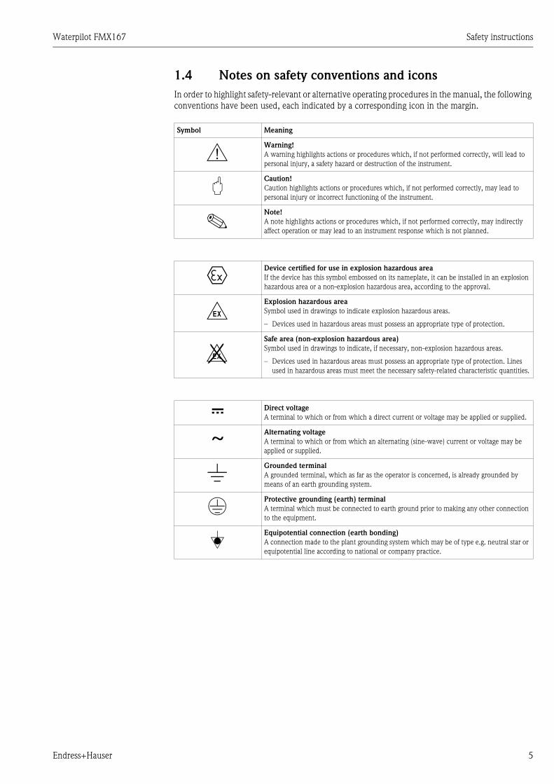
1.4 Notes on safety conventions and icons
In order to highlight safety-relevant or alternative operating procedures in the manual, the following
conventions have been used, each indicated by a corresponding icon in the margin.
Symbol Meaning
#Warning!
A warning highlights actions or procedures which, if not performed correctly, will lead to
personal injury, a safety hazard or destruction of the instrument.
"Caution!
Caution highlights actions or procedures which, if not performed correctly, may lead to
personal injury or incorrect functioning of the instrument.
!Note!
A note highlights actions or procedures which, if not performed correctly, may indirectly
affect operation or may lead to an instrument response which is not planned.
0Device certified for use in explosion hazardous area
If the device has this symbol embossed on its nameplate, it can be installed in an explosion
hazardous area or a non-explosion hazardous area, according to the approval.
-Explosion hazardous area
Symbol used in drawings to indicate explosion hazardous areas.
Devices used in hazardous areas must possess an appropriate type of protection.
. Safe area (non-explosion hazardous area)
Symbol used in drawings to indicate, if necessary, non-explosion hazardous areas.
Devices used in hazardous areas must possess an appropriate type of protection. Lines
used in hazardous areas must meet the necessary safety-related characteristic quantities.
% Direct voltage
A terminal to which or from which a direct current or voltage may be applied or supplied.
&Alternating voltage
A terminal to which or from which an alternating (sine-wave) current or voltage may be
applied or supplied.
)Grounded terminal
A grounded terminal, which as far as the operator is concerned, is already grounded by
means of an earth grounding system.
*Protective grounding (earth) terminal
A terminal which must be connected to earth ground prior to making any other connection
to the equipment.
+Equipotential connection (earth bonding)
A connection made to the plant grounding system which may be of type e.g. neutral star or
equipotential line according to national or company practice.

Identification Waterpilot FMX167
6 Endress+Hauser
2 Identification
2.1 Device designation
Waterpilot FMX167 for hydrostatic level measurement, refer to Section 2.1.1.
Waterpilot FMX167 with optional Pt 100 resistance thermometer for simultaneous
level and temperature measurement, refer to Section 2.1.1.
Waterpilot FMX167 with optional Pt 100 resistance thermometer and optional temperature
transmitter TMT181, refer to Sections 2.1.1 and 2.1.2.
2.1.1 Nameplate Waterpilot FMX167
The nameplate is fitted to the FMX167 extension cable.
P01-FMX167xx-18-xx-xx-xx-003
Fig. 1: Nameplate for Waterpilot FMX167
1 Order code
See the specifications on the order confirmation for the meaning of the individual letters and digits.
2 Serial number
3 Length of extension cable
4 Nominal measuring range
5 Current output
6 Supply voltage
7 TAG
8 Wetted materials
9 Ex symbol (optional)
10 CSA symbol (optional)
11 FM symbol (optional)
12 Pay attention to the installation instructions in the Operating Instructions!
13 ID number of notified body with regard to ATEX (optional)
14 Text for approval (optional)
15 Approval symbol (optional)
16 Test date (optional)
17 Symbol: Observe Safety Instructions, indicating the documentation number, e.g. XA131P-C (optional)
18 Wiring diagram FMX167
19 Wiring diagram Pt 100 if Waterpilot was ordered with Pt 100.
Ser.-No.:Order Code: L=
Mat:
Messbereich/range:
Dat./Insp.:
25
00
00
87
4-C
TAG:
Vmax:
Waterpilot FMX167
Made in Germany, D-79689 Maulburg
8
10
5
12
3
4
9
67
1211
18
1914 15
16 17
13

Waterpilot FMX167 Identification
Endress+Hauser 7
The following information is also provided on the FMX167 with outer diameter = 22 mm (0.87 in)
and 42 mm (1.66 in):
P01-FMX167xx-18-xx-xx-xx-004
Fig. 2: FMX167 labeling
1 Serial number
2 Nominal measuring range
3 CE symbol or approval symbol
4 ID number of notified body with regard to ATEX (optional)
5 Text for approval (optional)
2.1.2 Nameplate of temperature transmitter TMT181
P01-FMX167xx-18-xx-xx-xx-002
Fig. 3: Nameplate of temperature transmitter TMT181
1 Order code of temperature transmitter TMT181-A41DA
A: Version for non-hazardous area
4: 4-wire
1: Sensor Pt 100
D: Temperature transmitter with settings for 20+80°C (4+174°F) range
A: Label: Standard version
2 Serial No.
3 Current output: 420 mA
4 Supply voltage: 835 V DC
2.2 Scope of supply
The scope of delivery comprises:
Waterpilot FMX167, optionally with integrated Pt 100 resistance thermometer
Optional accessories (→ see also Chapter 7)
Documentation supplied:
Operating Instructions BA231P (this document)
Final inspection report
Drinking water approval SD126P (optional)
Devices which are suitable for use in hazardous areas:
additional documentation such as Safety Instructions (XAs), Control or
Installation Drawings (ZDs)
Waterpilot FMX167
Serial-No.:Messbereich/range:
12
35
4

Installation Waterpilot FMX167
8 Endress+Hauser
2.3 CE mark, declaration of conformity
The device is designed to meet state-of-the-art safety requirements, has been tested and left the
factory in a condition in which it is safe to operate. The device complies with the applicable
standards and regulations as listed in the EC declaration of conformity and thus complies with the
statutory requirements of the EC Directives. Endress+Hauser confirms the successful testing of the
device by affixing to it the CE mark.
3 Installation
3.1 Incoming acceptance and storage
3.1.1 Incoming acceptance
Check the packaging and the contents for damage.
Check the shipment, make sure nothing is missing and that the scope of supply matches your
order.
3.1.2 Storage
The device must be stored in a dry, clean area and protected against damage from impact
(EN 837-2).
Storage temperature range:
FMX167: 40...+80°C (40...+176°F)
TMT181: 40...+100°C (40...+212°F)

Waterpilot FMX167 Installation
Endress+Hauser 9
3.2 Installation conditions
P01-FMX167xx-11-xx-xx-xx-003
Fig. 4: Installation examples
For accessories see Page 18, Chapter 7.
1 Extension cable mounting screw can be ordered via order code or as an accessory
2 Terminal housing can be ordered via order code or as an accessory
3 Extension cable bending radius > 120 mm (4.72 in)
4 Mounting clamp can be ordered via order code or as an accessory
5 Extension cable up to 300 m (384 ft)
6 Guide tube
7 Additional weight can be ordered as an accessory
8 Protection cap
! Note!
A sideways movement of the level probe can lead to measuring errors. Therefore install the probe
at a point free from flow and turbulence, or use a guide tube. The internal diameter of the guide
tube should be at least 1 mm (0.04 in) bigger than the outer diameter of the selected FMX167.
The cable must end in a dry room or in a proper terminal box. The terminal box from
Endress+Hauser provides optimum humidity and climatic protection and is suitable for outdoor
installation.
Protective cap: to avoid mechanical damage to the measuring cell, the device is provided with a
protective cap.
You can order protective caps (5 pieces per set) as spare part directly from your Endress+Hauser
Service Organisation using Order No.: 52008999.
➀
➂
➁
➃
➄
➅
➆
➇
FMX167
OPEN
CLOSE
90°
90°
Wa
terp
ilot
FM
X1
67
Se
ria
l-N
o.:
XX
XX
XX
XX
XX
XM
essbe
reic
h/r
an
ge
:0..
.30
0f tH
20
INT.S
AF
E,
CL.I
,D
IV.1
,G
P.A
BC
DN
ON
INC
EN
DIV
EC
L.I
,D
IV.2
,G
P.A
BC
DA
Ex
iaII
CT
6,Ta
=7
0°C
Entity
pe
rd
wg
.9
60
50
3-1
00
9-

Installation Waterpilot FMX167
10 Endress+Hauser
3.2.1 Dimensions
→ For dimensions, please refer to the Technical Information for Waterpilot TI351P, "Mechanical
construction" section (→ see also: www.endress.com → Download).
3.3 Installation instructions
3.3.1 Installing Waterpilot with a mounting clamp
P01-FMX167xx-17-xx-xx-xx-004
Fig. 5: Installing Waterpilot FMX167 with a mounting clamp
1 Extension cable
2 Mounting clamp
3 Clamping jaws
How to mount the mounting clamp:
1. Mount the mounting clamp (Pos. 2). When selecting the type of fixing, note the weight of the
extension cable (Pos. 1) and the device.
2. Raise clamping jaws (Pos. 3). Place extension cable (Pos. 1) acc. to Figure 5 between clamping
jaws.
3. Hold extension cable (Pos. 1) tight and push clamping jaws (Pos. 3) back down.
Fix clamping jaws by tapping lightly.
➀
➂
➁

Waterpilot FMX167 Installation
Endress+Hauser 11
3.3.2 Installing Waterpilot with cable mounting screw
P01-FMX167xx-17-xx-xx-xx-005
Fig. 6: Installing the Waterpilot FMX167 with cable mounting screw, here depicted with G 1 1/2 thread
1 Extension cable
2 Mounting screw cap nut
3 Sealing ring
4 Clamping sleeve
5 Mounting screw adapter
6 Top edge of clamping sleeve
7 required length of extension cable and FMX167 probe before assembly
7 after assembly Pos. 7 is located next to the mounting screw with
G 1 1/2 thread: sealing surface of mounting screw adapter
1 1/2 NPT thread run-out of mounting screw adapter
! Note!
If you want to lower the level probe to a certain depth, place the top edge of the clamping sleeve
4 cm (1.57 in) higher than the required depth. Then push the extension cable and the clamping
sleeve into the adapter as described in the following Section, Step 6.
How to mount the cable mounting screw with G 1 1/2 or NPT thread:
1. Mark required length of extension cable, refer to "Note" on this Page.
2. Insert probe through measuring opening and carefully lower on extension cable.
Fix extension cable to prevent it from slipping.
3. Push adapter (Pos. 5) over extension cable and screw tightly in measuring opening.
4. Push sealing ring (Pos. 3) and cap (Pos. 2) from top onto cable. Press sealing ring into cap.
5. Place clamping sleeve (Pos. 4) around extension cable (Pos. 1) acc. to Figure 6.
➀
➂
➁
➃
➄
➅
➆
➆
SW 36
41 AFSW 41
36 AF
+ 4
cm
'
Installation Waterpilot FMX167
12 Endress+Hauser
6. Push extension cable and clamping sleeve (Pos. 4) into adapter (Pos. 5).
7. Push cap (Pos. 2) and sealing ring (Pos. 3) onto adapter (Pos. 5) and screw tightly to adapter.
! Note!
Remove the cable mounting screw in the opposite sequence of operation to installation.
3.3.3 Mounting the terminal box
Mount the optional terminal box with four screws (M 4). → For dimensions of the terminal box,
please refer to the Technical Information for Waterpilot TI351P, "Mechanical construction" section
(→ see also: www.endress.com → Download).
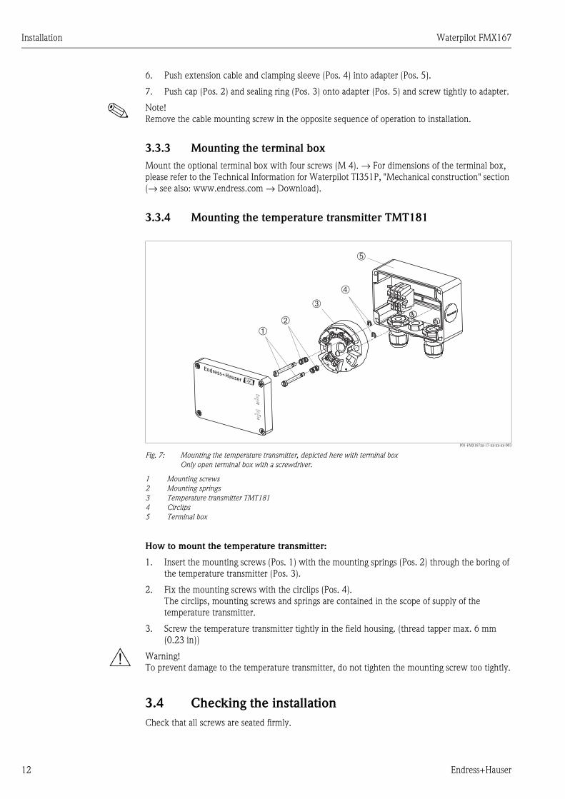
3.3.4 Mounting the temperature transmitter TMT181
P01-FMX167xx-17-xx-xx-xx-003
Fig. 7: Mounting the temperature transmitter, depicted here with terminal box
Only open terminal box with a screwdriver.
1 Mounting screws
2 Mounting springs
3 Temperature transmitter TMT181
4 Circlips
5 Terminal box
How to mount the temperature transmitter:
1. Insert the mounting screws (Pos. 1) with the mounting springs (Pos. 2) through the boring of
the temperature transmitter (Pos. 3).
2. Fix the mounting screws with the circlips (Pos. 4).
The circlips, mounting screws and springs are contained in the scope of supply of the
temperature transmitter.
3. Screw the temperature transmitter tightly in the field housing. (thread tapper max. 6 mm
(0.23 in))
# Warning!
To prevent damage to the temperature transmitter, do not tighten the mounting screw too tightly.
3.4 Checking the installation
Check that all screws are seated firmly.
➀
➂
➁
➃
➄
CLOSE
90°
OPEN
90°
Waterpilot FMX167 Wiring
Endress+Hauser 13
4 Wiring
4.1 Connecting the device
! Note!
When using the measuring device in hazardous areas, installation must comply with the
corresponding national standards and regulations and the Safety Instructions (XAs) or Installation or
Control Drawings (ZDs).
The supply voltage must match the supply voltage on the nameplate. (→ See also Page 6 ff,
Sections 2.1.1 and 2.1.2.)
Switch off supply voltage before you connect the device.
The cable must end in a dry room or in a proper terminal box. The terminal box with GORE-TEX®
filter, IP 66/IP 67 from Endress+Hauser is suitable for outdoor installation.
Connect device acc. to the following figures. A polarity protection is integrated in the Waterpilot
FMX167 and the temperature transmitter TMT181. Changing the polarities will not destroy the
devices.
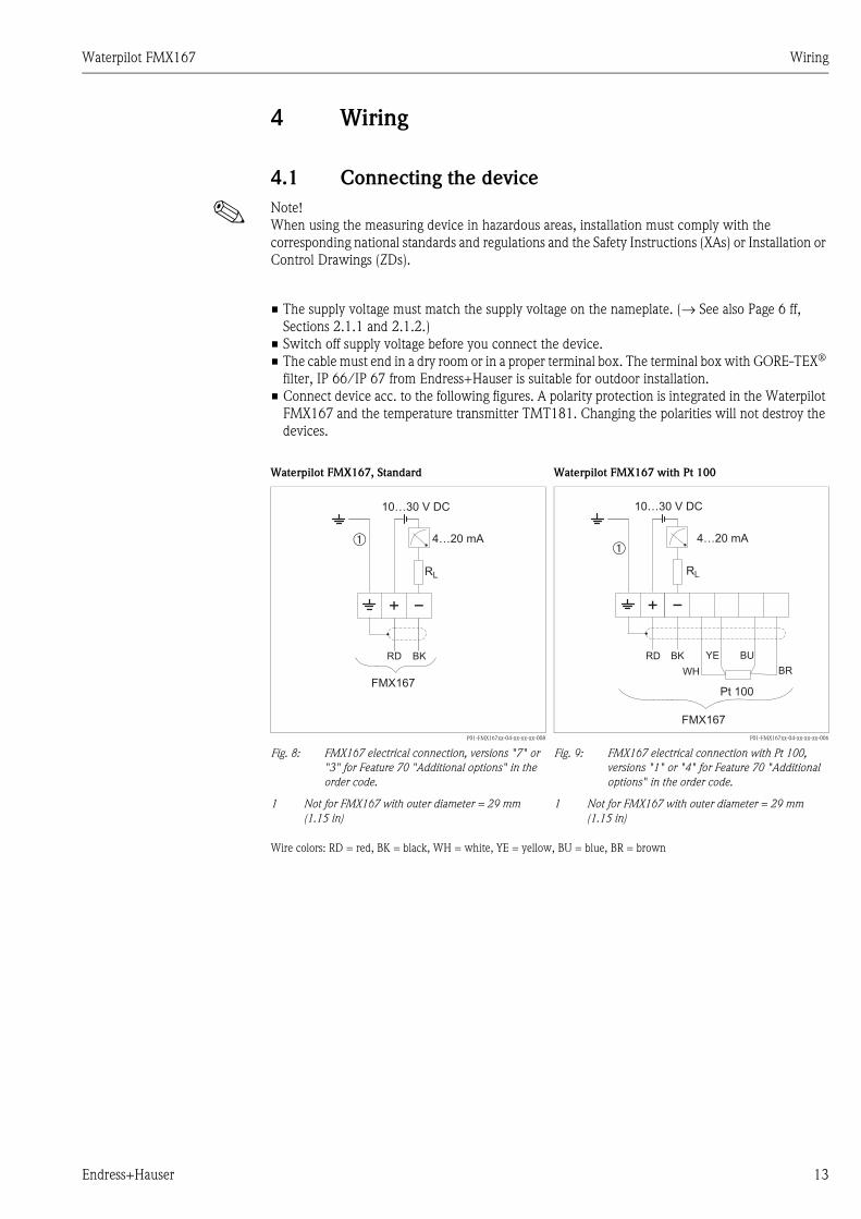
Waterpilot FMX167, Standard Waterpilot FMX167 with Pt 100
P01-FMX167xx-04-xx-xx-xx-008
Fig. 8: FMX167 electrical connection, versions "7" or
"3" for Feature 70 "Additional options" in the
order code.
1 Not for FMX167 with outer diameter = 29 mm
(1.15 in)
P01-FMX167xx-04-xx-xx-xx-006
Fig. 9: FMX167 electrical connection with Pt 100,
versions "1" or "4" for Feature 70 "Additional
options" in the order code.
1 Not for FMX167 with outer diameter = 29 mm
(1.15 in)
Wire colors: RD = red, BK = black, WH = white, YE = yellow, BU = blue, BR = brown
RD BK
FMX167
RL
4…20 mA
10…30 V DC
➀
FMX167
Pt 100
RD BK
WH
YE BU
BR
10…30 V DC
4…20 mA
RL
➀

Wiring Waterpilot FMX167
14 Endress+Hauser
4.1.1 Supply voltage
4.1.2 Cable specification
FMX167 with optional Pt 100
Commercially available installation cable
Terminals in terminal box FMX 167: 0.082.5 mm2
Temperature transmitter TMT181 (optional)
Commercially available installation cable
Terminals in terminal box FMX 167: 0.082.5 mm2
Transmitter terminals: max. 1.75 mm2
! Note!
For versions with outer diameter = 22 mm (0.87 in) and 42 mm (1.66 in) the extension cables are
shielded. In the following cases Endress+Hauser recommends use of a shielded cable for the cable
extension:
for large distances between extension cable end and display and/or evaluation unit,
for large distances between extension cable end and temperature transmitter
for directly connecting Pt 100 signals to the display and/or evaluation unit.
Waterpilot FMX167 with Pt 100 and temperature transmitter TMT181 (4...20 mA)
P01-FMX167xxx-04-xx-xx-xx-007
Fig. 10: FMX167 with Pt 100 and TMT181 temperature transmitter (4...20 mA),
version "5" for Feature 70 in the order code
1 Not for FMX167 with outer diameter = 29 mm (1.15 in)
Wire colours: RD = red, BK = black, WH = white, YE = yellow, BU = blue, BR = brown
Certificate Supply voltage
FMX167 FMX167 + Pt 100 Temperature transmitter
TMT181
Standard 10...30 V DC 10...30 V DC 8...35 V DC
2
1
6
5
4
3
Pt 100
RD BK
WH
YE BU
BR
FMX167
8…35 V DC
4…20 mA
10…30 V DC
4…20 mA
TMT181 (4…20 mA)
RL
RL
➀

Waterpilot FMX167 Wiring
Endress+Hauser 15
4.1.3 Power consumption/current drain
4.1.4 Load
The maximum load resistance is dependent on the supply voltage (Ub) and must be determined for
every current loop separately. Refer to the equations and diagrams for "FMX 167" and "Temperature
transmitter".
The total resistance resulting from the resistances of the connected devices, the connecting cable
and if necessary, the resistor of the extension cable may not exceed the load resistance.
FMX167 FMX167 + Pt 100 Temperature transmitter
TMT181
Power consumption ≤ 0.675 W at 30 V DC ≤ 0.675 W at 30 V DC ≤ 0.875 W at 35 V DC
Current drain max. ≤ 22.5 mA
min. ≥ 3.5 mA
max. ≤ 22.5 mA
min. ≥ 3.5 mA
Pt 100: ≤ 0.6 mA
max. ≤ 25 mA
min. ≥ 3.5 mA
FMX167 Temperature transmitter
P01-FMX167xx-16-xx-xx-xx-000 P01-FMX167xx-16-xx-xx-xx-001
Rtot ≤ – 2 • 0.09 • l – Radd
U – 10 Vb
0.0225 A
Ωm
Rtot ≤ – Radd
U – 8 Vb
0.025 A
Rtot = Max. load resistance [Ω]
Radd = additional resistances, e.g. resistance of evaluating device and/or the display instrument, line resistance [Ω]
Ub = Supply voltage [V]
l = Simple length of extension cable [m] (cable resistance per wire ≤ 0,09 Ω/m)
P01-FMX167xx-05-xx-xx-xx-001
Fig. 11: Load chart FMX167 for estimating load
resistance. Subtract the additional
resistances, e.g. resistance of extension cable,
from the calculated value as shown in the
equation.
P01-FMX167xx-05-xx-xx-xx-003
Fig. 12: Load chart temperature transmitter for
estimating load resistance. Subtract the
additional resistances from the calculated
value as shown in the equation.
888
444
666
222
3020 2510 15
R[ ]Ω
[V]
UB 3020 25158 3510
1080
880
480
280
680
80
R[ ]Ω
[V]
UB

Wiring Waterpilot FMX167
16 Endress+Hauser
4.2 Wiring up the measuring unit
4.2.1 Overvoltage protection
! Note!
In order to protect the Waterpilot FMX167 and the temperature transmitter TMT181 from large
transients, Endress+Hauser recommends the installation of an overvoltage protector upstream
and downstream of the display and/or evaluation device as shown in the figure.
The Waterpilot FMX 167 has an integrated overvoltage protection to EN 61000 of ≤ 1.2 kV as
standard.
P01-FMX167xx-14-xx-xx-de-006
Fig. 13: Wiring up the measuring unit
1 Power supply, display and evaluation unit with one input for Pt 100
2 Power supply, display and evaluation unit with one input for 4...20 mA
3 Power supply, display and evaluation unit with two inputs for 4...20 mA
OP Overvoltage protection e.g. HAW from Endress+Hauser
4.3 Checking the wiring
Perform the following checks after completing electrical installation of the device:
Does the supply voltage match the specifications on the nameplate?
Is the device connected as per Section 4.1?
Are all screws firmly tightened?
Optional terminal box: are the cable glands tight?
Pt 100
Pt 100 4…20 mA
➀
➁
➁
➂
FM
X16
7 +
Pt 1
00
4…20 mA
4…20 mA
4…20 mA
Wate
rpilo
tF
MX
167
Se
ria
l-N
o.:
XX
XX
XX
XX
XX
XM
essb
ere
ich
/ra
ng
e:
0..
.30
0ftH
20
INT.S
AF
E,
CL
.I,
DIV
.1,
GP.A
BC
DN
ON
INC
EN
DIV
EC
L.I
,D
IV.2
,G
P.A
BC
DA
Ex
iaII
CT
6,Ta
=7
0°C
En
tity
pe
rd
wg
.9
60
50
3-1
00
9-
Powersupply
Temperature
Temperature
Level
Level
OP
OP
OP
OP
Powersupply
OP
OP
Powersupply
OP
Waterpilot FMX167 Operation
Endress+Hauser 17
5 Operation
! Note!
Endress+Hauser offers extensive measuring point solutions with display and/or evaluation units for
the Waterpilot FMX167 and the temperature transmitter TMT181. For more information, please
contact your nearest Endress+Hauser Service Organisation. For contact addresses, please go to
www.endress.com/worldwide.
6 Maintenance
No special maintenance work is required for the Waterpilot FMX167 or for the optional temperature
transmitter TMT181.
6.1 Exterior cleaning
Please note the following points when cleaning the exterior of the device:
Do not use a cleaning agent that is aggressive to the housing surface or the seal.
Waterpilot FMX167: avoid any mechanical damage to the membrane or the extension cable.
Accessories Waterpilot FMX167
18 Endress+Hauser
7 Accessories
There are a number of accessories available for the Waterpilot FMX167. You can order them
separately from Endress+Hauser.
Mounting clamp
Endress+Hauser offers a mounting clamp for simple FMX167 mounting. → See also Page 10,
Section 3.3.1.
Material: 1.4435 (AISI 316L) and glass fiber reinforced PA (polyamide)
Order number: 52006151
Terminal box
Terminal box IP 66/IP 67 with GORE-TEX® filter incl. 3 mounted terminals.
The terminal box is also suitable for installing a temperature transmitter (Order No. 52008794)
or for four additional terminals (Order No. 52008938). → See also Page 12, Section 3.3.4.
Order number: 52006152
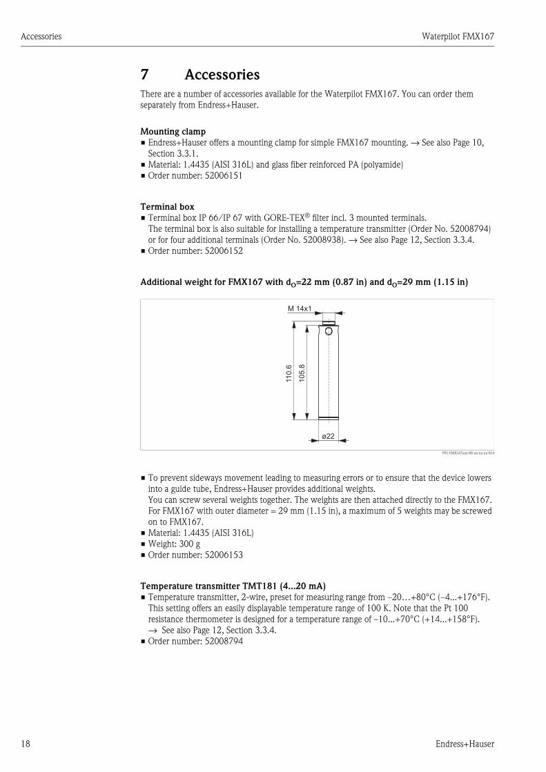
Additional weight for FMX167 with dO=22 mm (0.87 in) and dO=29 mm (1.15 in)
P01-FMX167xxx-06-xx-xx-xx-014
To prevent sideways movement leading to measuring errors or to ensure that the device lowers
into a guide tube, Endress+Hauser provides additional weights.
You can screw several weights together. The weights are then attached directly to the FMX167.
For FMX167 with outer diameter = 29 mm (1.15 in), a maximum of 5 weights may be screwed
on to FMX167.
Material: 1.4435 (AISI 316L)
Weight: 300 g
Order number: 52006153
Temperature transmitter TMT181 (4...20 mA)
Temperature transmitter, 2-wire, preset for measuring range from 20+80°C (4...+176°F).
This setting offers an easily displayable temperature range of 100 K. Note that the Pt 100
resistance thermometer is designed for a temperature range of 10...+70°C (+14...+158°F).
→ See also Page 12, Section 3.3.4.
Order number: 52008794
ø22
M 14x1105.8
110.6

Waterpilot FMX167 Accessories
Endress+Hauser 19
Cabel mounting screw
Endress+Hauser offers extension cable mounting screws to simplify the installation of the
FMX167 and to close the measuring open. → See also Page 11, Section 3.3.2.
Material: 1.4301 (AISI 304)
Order number for extension cable mounting screw with G 1 1/2 A thread: 52008264
Order number for extension cable mounting screw with 1 1/2 NPT thread: 52009311
Terminals
Four terminals in strip for FMX167 terminal box, suitable for wire cross-section of
0.082.5 mm2
Order number: 52008939
Test adapter for FMX167 with dO=22 mm (0.87 in) and dO=29 mm (1.15 in)
P01-FMX167xxx-06-xx-xx-xx-013
Abb. 14: Test adapter
A Connection suitable for level probe FMX167
B Connection compressed air hose, internal diameter, quick hose gland 4 mm (0.157 in)
Endress+Hauser offers a test adapter to simplify the function test of level probes.
Note the maximum pressure for the compressed air hose and the maximum level probe overload.
(→ For the maximum level probe overload refer to Technical Information for Waterpilot TI351P
or Internet: www.endress.com → Download)
The maximum pressure for the supplied quick hose gland is 10 bar (145 psi).
Adapter material: 1.4301 (AISI 304)
Quick hose gland material: Anodized aluminum
Adapter weight: 39 g
Order number: 52011868
SW 12
M 14x1
~25
~33
SW 22
SW 13
A
22 AF
13 AF
12 AF
Trouble-shooting Waterpilot FMX167
20 Endress+Hauser
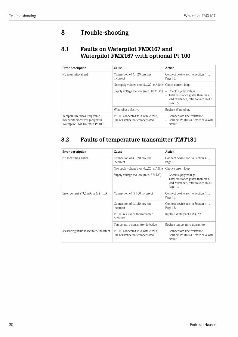
8 Trouble-shooting
8.1 Faults on Waterpilot FMX167 andWaterpilot FMX167 with optional Pt 100
8.2 Faults of temperature transmitter TMT181
Error description Cause Action
No measuring signal Connection of 420 mA line
incorrect
Connect device acc. to Section 4.1,
Page 13.
No supply voltage over 420 mA line Check current loop.
Supply voltage too low (min. 10 V DC) Check supply voltage.
Total resistance grater than max.
load resistance, refer to Section 4.1,
Page 15.
Waterpilot defective Replace Waterpilot.
Temperature measuring value
inaccurate/incorrect (only with
Waterpilot FMX167 with Pt 100)
Pt 100 connected to 2-wire circuit,
line resistance not compensated
Compensate line resistance.
Connect Pt 100 as 3-wire or 4-wire
circuit.
Error description Cause Action
No measuring signal Connection of 420 mA line
incorrect
Connect device acc. to Section 4.1,
Page 13.
No supply voltage over 420 mA line Check current loop.
Supply voltage too low (min. 8 V DC) Check supply voltage.
Total resistance grater than max.
load resistance, refer to Section 4.1,
Page 13.
Error current ≤ 3,6 mA or ≥ 21 mA Connection of Pt 100 incorrect Connect device acc. to Section 4.1,
Page 13.
Connection of 420 mA line
incorrect
Connect device acc. to Section 4.1,
Page 13.
Pt 100 resistance thermometer
defective
Replace Waterpilot FMX167.
Temperature transmitter defective Replace temperature transmitter.
Measuring value inaccurate/incorrect Pt 100 connected in 2-wire circuit,
line resistance not compensated
Compensate line resistance.
Connect Pt 100 as 3-wire or 4-wire
circuit.

Waterpilot FMX167 Technical Data
Endress+Hauser 21
8.3 Spare Parts
! Note!
You can order spare parts directly from your nearest Endress+Hauser Service Organisation.
Membrane protective cap
5 pieces in set
Order No.: 52008999
Pressure compensation set
10 pieces in set, comprising Teflon filter and sleeve for extension cable
Order No.: 52005578
9 Technical Data
For technical data, please refer to the Technical Information for Waterpilot TI351P
(→ see also: www.endress.com → Download).

Waterpilot FMX167 Index
22 Endress+Hauser
Index
AAccessories. . . . . . . . . . . . . . . . . . . . . . . . . . . . . . . . . . . . 18
CCable specification . . . . . . . . . . . . . . . . . . . . . . . . . . . . . . 14
Current drain . . . . . . . . . . . . . . . . . . . . . . . . . . . . . . . . . . 15
EElectrical connection . . . . . . . . . . . . . . . . . . . . . . . . . . . . 13
IIncoming acceptance . . . . . . . . . . . . . . . . . . . . . . . . . . . . . 8
LLoad . . . . . . . . . . . . . . . . . . . . . . . . . . . . . . . . . . . . . . . . 15
MMembrane protective cap . . . . . . . . . . . . . . . . . . . . . . . . . 21
Mounting cable mounting screw. . . . . . . . . . . . . . . . . . . . 11
Mounting clamp. . . . . . . . . . . . . . . . . . . . . . . . . . . . . . . . 10
Mounting Temperature transmitter TMT181 . . . . . . . . . . 12
Mounting terminal box. . . . . . . . . . . . . . . . . . . . . . . . . . . 12
NNameplate Temperature transmitter TMT181. . . . . . . . . . . 7
Nameplate Waterpilot FMX167 . . . . . . . . . . . . . . . . . . . . . 6
OOvervoltage protection . . . . . . . . . . . . . . . . . . . . . . . . . . . 16
PPower consumption . . . . . . . . . . . . . . . . . . . . . . . . . . . . . 15
Pressure compensation set . . . . . . . . . . . . . . . . . . . . . . . . 21
SStorage. . . . . . . . . . . . . . . . . . . . . . . . . . . . . . . . . . . . . . . . 8
Supply voltage . . . . . . . . . . . . . . . . . . . . . . . . . . . . . . . . . 14

Erklärung zur Kontamination
P/S
F/K
onta
VIII
Declaration of Contamination
Because of legal regulations and for the safety of our employees and operating equipment, we need the "declaration of
contamination", with your signature, before your order can be handled. Please make absolutely sure to include it with
the shipping documents, or - even better - attach it to the outside of the packaging.
Aufgrund der gesetzlichen Vorschriften und zum Schutz unserer Mitarbeiter und Betriebseinrichtungen, benötigen wir die
unterschriebene "Erklärung zur Kontamination", bevor Ihr Auftrag bearbeitet werden kann. Legen Sie diese unbedingt den
Versandpapieren bei oder bringen Sie sie idealerweise außen an der Verpackung an.
Serial number
Seriennummer ___________________
Type of instrument / sensor
Geräte-/Sensortyp _______________________________________
Process data/Prozessdaten Temperature / _________ [°C]
Conductivity / _________ [ S ]
Temperatur
Leitfähigkeit
Pressure / __________ [ Pa ]
Viscosity / __________ [mm /s]
Druck
Viskosität2
corrosive
ätzend
harmless
unbedenklich
other *
sonstiges*
toxic
giftig
Process
medium
Identification
CAS No.
flammable
entzündlich
harmful/irritant
gesundheits-schädlich/
reizend
Medium /concentration
Medium /Konzentration
Returned part
cleaned with
Medium for
process cleaning
Medium and warnings
Warnhinweise zum Medium
* explosive; oxidising; dangerous for the environment; biological risk; radioactive
* explosiv; brandfördernd; umweltgefährlich; biogefährlich; radioaktiv
Please tick should one of the above be applicable, include security sheet and, if necessary, special handling instructions.
Zutreffendes ankreuzen; trifft einer der Warnhinweise zu, Sicherheitsdatenblatt und ggf. spezielle Handhabungsvorschriften beilegen.
Reason for return / Grund zur Rücksendung _____________________________________________________________
__________________________________________________________________________________________________
__________________________________________________________________________________________________
We hereby certify that the returned parts have been carefully cleaned. To the best of our knowledge they are free from any residues in
dangerous quantities.
Hiermit bestätigen wir, dass die zurückgesandten Teile sorgfältig gereinigt wurden, und nach unserem Wissen frei von Rückständen in
gefahrbringender Menge sind.
_____________________________________________
(place )Ort, Datum, date /
______________________________________________
(Company stamp and legally binding signature)
(Firmenstempel und rechtsverbindliche Unterschrift)
Company data /Angaben zum Absender
Company / ________________________________
______________________________________________
Address /
______________________________________________
______________________________________________
Firma
Adresse
Contact person / ______________________
Department / ______________________________
P ______________________________
Fax / E-Mail _______________________________________
Y _______________________
Ansprechpartner
Abteilung
Telefon
Ihre Auftragsnr.
hone number/
our order No. /
Medium zur
Endreinigung
Medium zur
Prozessreinigung
Medium im
Prozess

www.endress.com/worldwide
BA231P/00/en/08.05
71003557
CCS/FM+SGML6.0 71003557