waterwash spray booth water treatment - p2ric
TRANSCRIPT
WATERWASH SPRAY BOOTH WATER TREATMENT
WEDNESDAYt APRIL 27, 1994 (10:50-11~15 AM)
Alan Monken Technical Service Chemist
Calgon Corporation
1177 N. Warson Road Suite 103
St. Louis, MO 63132
1-800-345-9697

TIPS FOR WATERWASH SPRAY BOOTH WATER TREATMENT AND MAINTENANCE
Tip #1:
Tip #2:
Tip #3:
Tip # 4 :
Tip #5:
Tip #6:
Tip #7:
Tip #8:
Tip #9:
When selecting new spray booth equipment, be sure that the system configuration is not only optimum for production workflow and volume of paint sprayed, but also suitable for paint type(s) to allow complete detackification and removal.
When changing to ftcompliancelt coatings, be aware that these coatings often require a change of chemical program to treat these paints.
When introducing higher solids paints requiring different chemical treatment programs (like polymers) into older existing systems, make sure that adequate agitation and circulation exists to optimize the treatment.
Paint detackification programs should be selected with regard to both paint type (i.e. waterborne vs. solventborne coatings) and system sophistication/ complexity. Don't over-engineer the system!
When evaluating chemical programs, be sure to compare total cost, including labor (cleanout and maintenance) costs and sludge disposal savings (due to reduction of volume).
Be wary of "savings" from switching to dry filter systems; savings in chemical usage can be offset by increases in disposal/handling costs as well as flammability hazards.
When switching t3 waterborne coatings, don't forget the potential benefits of having sludge reclassified as non-hazardous (if applicable).
When possible (especially with waterborne coatings) co-mingle paint booth water with waste water to reduce costs associated with sludge removal and handling and get more utilization of waste treatment.
A s with chemical treatment programs, evaluate sludge removal equipment with regard to system fit and applicability. There are benefits from most equipment but not with all systems.
Waterwash Spray Booth Water Treatment
In the area of waterwash spray booths, the selection of the proper method of detackifying and/or handling paint overspray is critical to the success of the operation. Improper selection or use of treatment chemicals can result in blocked nozzles and flood sheets, in greater labor costs due to booth shutdowns for cleanout, and in the emission of paint spray through exhaust stacks. Most of these problems, however, can be avoided through the proper maintenance of the paint booth system and treatment program. In order to better understand how to select the right program and keep the booth operating correctly, it is important to have an understanding of the types of chemical treatment available for waterwash systems, of the booth systems themselves, and of methods for paint solids removal from the systems.
METHODS OF PAINT DETACKIFICATION
Since the advent of wet spray booths, there have been a number of chemical means developed to detackify solvent-based paints as well as water-borne coatings. For solvent-based paints, the most common treatments have been:
1) Caustic/Hydroxide Treatments
The use of caustic-based treatments (most commonly in the form of Sodium Hydroxide) represents the oldest chemically-based treatment for detackification. These products work well lacquers (paints cured by solvent loss), which made up many of low- solids paints of the past. The basic principle of detackification is the cleavage of ester linkages found in the fatty-acid based resin by hydroxide (OH-). This results in the formation of a metal-based soap, which acts as to emulsify any remaining solvents in the paint. The remaining material, with no solvent present, cures and hardens into a mass for ffeasylf removal.
The drawback of the caustic-based program is that, as paint technology advanced, with higher solids levels and catalyzed curing, this type of treatment no longer fully reacts with the components of the paint. This results in only partially-killed paint, which causes most of the same problems as 'flivelf paint. To combat this problem, caustic-based programs containing some insoluble inorganic material (such as lime) were developed. The insoluble material helps to capture some of the unkilled mass of the paint, essentially embedding it. Even these modified programs are inefficient, however, as the solids-level of the paint increases past 25%.
2) Metal Salts Programs
Metal Salts products primarily make use of aluminum and zinc salts combined with a source of alkalinity to form either catalyzed insoluble metal soaps (somewhat similar to the treatment with caustic) or suspended metal complexes which can be removed by
treatment with an additional polymer. The limitations of this type of treatment is that, except in
the case of alkyd-based air-cured paints, the pH control of the system is very crucial to proper operation. Fluctuations in pH level can easily cause disruption of the program, resulting in live paint and settling solids.
3 ) Clay-based Programs
Clay-based products primarily represent a physical, rather than chemical, method of paint detackification. As bentonite clay absorbs water, it swells to a large irregularly-surfaced material. Sticky paint particles entering the water containing this clay adhere to the outside surface and are, in turn, covered by other clay particles. This results in a large detackified mass. An amine is often fed to increase the paint's tendency to disperse prior to contact.
Although the clay itself is relatively inexpensive as treatments go, large amounts of clay or clay slurry are often required to maintain good detackification. This produces voluminous amounts of sludge, as compared with other treatment types. In addition, both water and solvent are often trapped in the clay matrix, making it difficult for landfill and limiting it's ability to be dewatered to a range of 20 to 25% maximum. Clay programs also typically have problems with foaming and biological contamination, due to the entrapment of paint and water in the clay sludge.
4 ) Acid Colloid Programs
The Acid Colloid treatments function on the principle that certain mixtures of hydrophillic (I1water-lovingf1) and hydrophobic ( "water-hatingI1) materials can form stable suspensions under acidic conditions but precipitate as associated complexes as the pH increases. There are three detackification programs currently used based on this principle: silicate amine programs, silica amine programs, and organic polymer programs. The basic principle is to feed the product into the system at a raised pH/alkalinity level in order to form the associated complex. The hydrophobic end orients onto the hydrophobic paint particle, with the hydrophillic end sticking into the water phase. This effectively allows the paint particle to be coated with a thin film of water that prevents its surface from adhering to other surfaces.
Silicate Amines: In this treatment, the hydrophillic portion is a polyamine and the hydrophobe is a silicate (usually Sodium Metasilicate). These materials are fed separately to the booth in a fixed ratio based on the paint overspray rate. (Most typically 4- 13 parts silicate to 1 part polyamine and both at 5-15% based upon overspray.) The pH level is critical, since too high a pH can cause the complex to redissolve.
The main drawback in Silicate Amine treatments is that they do not disperse paints very well nor do they provide uncommon to find
sticky deposits in the backsections of spraybooths where good mixing does not occur. Better detackification usually takes place as the system runs longer.
Silica Amines: The primary difference between Silicate Amines and Silica Amine Programs is that they utilize an aqueous colloidal silica s o l as the hydrophobe. Colloidal silica can be thought of somewhat as a nonswelling clay. The silica sol is fed at a ratio of 1-3 parts to each part of polyamine. Since the pH of these materials is essentially neutral, an alkalinity source (usually KOH) is fed to bring the system pH to 8.0-9.0.
The primary drawback of this program is that under conditions of high shear, such as might take place with a centrifuge separator, the small size of the silica might not allow itself to fully embed onto the paint, resulting in partially-killed sludge.
Organic Polymers: Originally used for separation of solid wastes in water treatment applications, organic polymers have been used successfully for several years in the separation and detackification of paint overspray in waterwash systems. These polymers detackify paint using a principle similar to that found in the inorganic systems described above, the primary difference being the presence of both the hydrophillic and hydrophobic species on the same polymer molecule. Because both of these groups are on the same molecule, the effect of detackification is nearly instantaneous. Also, because the size of the detackifying agent is small relative to that of silicate or silica amine, the organic polymer systems coat the paint particle much more effectively. Because of the relative fragility of the coating, it is necessary to disperse the paint well; under conditions of high shear the coating can be ruptured, releasing sticky paint.
Where waterborne coatings are involved, the treatment scheie must often be changed. The majority of waterborne resins are formulated to be dispersed when in alkaline solutions, which makes any alkaline-based detackifier (such as a caustic-based or alkaline-salt based program) ineffectual. Likewise, as the paints are, for the most part, nontacky in a water environment, treatments like the clay programs that rely on the physical contact between the paint and the detackifier are also not effective. Organic polymer programs do work with waterborne coatings, although the application of these programs may be somewhat different than with solvent-based paints. One very promising method of treatment f o r waterbornes is the combination of organic polymer treatments with conventional waste water clarification equipment. The paint booth water containing these materials can often successfully be co- mingled with other waste water for combined treatment.
BASIC PAINT BOOTH PRINCIPLES
The primary function of all paint booths is removing paint overspray from the work environment. In that respect, paint booths represent the most significant piece of safety equipment in the plant. All booths operate by directing a controlled airflow through the painting area and away from the painter. The paint medium used to remove the llsolidll material - the paint resin, pigment, etc. - from the volatile (i.e. solvent) portion. The volatile portion typically is removed through an exhaust stack and is vented outside the plant. [This is one of the sources for plant VOC emissions.]
The Irf ilteringll (or solids-removal process) may involve dry paper filter media or water-flow of some kind. In dry filter booths, the paint solids are not llkilledll or detackified in any way; this results in an eventual accumulation of highly flammable, highly tacky masses (in the case, primarily, of solvent-borne coatings) of waste paint solids and used filter media. In water systems it is possible to chemically treat these same paint solids to put them in a form that is easily handled and removed.
Another type of dry booth growing in use in the metal finishing industry is the powder paint booth. In these, the paint is applied to parts in a dry state rather than as liquid paint. The powder paint is then baked and melted to form the coating. The majority of powder booths use some type of vacuum system to recollect the oversprayed powder for eventual reuse. These systems are typically self-contained and used only for a single paint or paint color, or use separate modules for variations in paint. In most cases, powder paint booths DO NOT require any chemical treatment for handling waste solids (and, in fact, produce very little waste solids, since much of the paint can be reapplied).
WET BOOTH TYPES
After the first segmentation of paint booth types into wet and dry booths, wet (i.e. waterflow) paint booths can further be broken down into side-draft and down-draft systems. Side-draft and down- draft systems differ in form and application, although both exist for the same function - to remove the paint overspray from the work area.
SIDE-DRAFT PAINT BOOTHS
Side-draft booths are so named because the air flow moves horizontally across the painting area to remove the overspray and solvent vapors. In an ideal situation, clean, filtered air would be directed to flow from behind the painter, and to the paint booth, where it would be pulled by exhaust fans through the waterflow and up the exhaust stacks. In many real-world situations, however, the air simply comes directly from the normal
ventilation of the plant environment. In these cases, it is extremely important to maintain the proper airflow fromthe exhaust and the correct level of waterflow in the booth.
Typically, side-draft booths (also commonly known as waterfall booths) are under 2000 gallons in volume, are used to paint small- to medium-sized parts hung on a conveyorized line, are run two shifts per day or less, and are cleaned on a frequent, periodic basis. This type of booth is most often available as a pre- engineered llpackage'l system, as opposed to large downdraft systems, which are typically unique to a particular plant application and are constructed on site by equipment contractors. Side-draft booths are found in most of lltypicalll Surface Finishing/Metal Cleaning accounts.
COMMON SIDE-DRAFT BOOTH TYPES
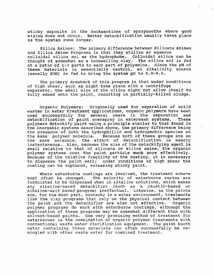
One of the most common waterwash booths found in small manufacturing is the D y n a p r e c i p i t o r b o o t h (manufactured by Binks). (Fig. 1) The principles behind this system are the use of a continuous curtain of moving water to scrub suspended paint solids particles out of a controlled airstream and the use of baffles, which force the air flow through directional
BINKS DYNAPRECIPITOR BOOTH (CRQSS SECTION)
changes, which further remove the solids. The particles removed are expected to settle in the collecting pan/water reservoir. The Dynaprecipitor is designed to operate with the tank water level at the bottom of the front flood sheet (water curtain). These booths are typically 500 to 1500 gallons in volume. There is also a version of this system with an extended front tank. This extension often results in booth circulationproblems, especially in regards to polymer treatment programs.
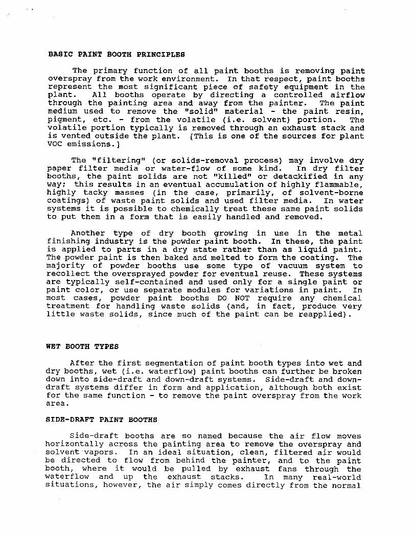
Binks also makes a booth called the Nopump system. (Fig. 2) This booth is designed to make use of an upwards high- velocity flow of air and water to scrub out the paint particles. This system has no water curtain: all the paint must be scrubbed directly from the air flow during its trip through the baffle system after
FNopUMP SPRAY BOOTH CROSS SECTION
ENTRAINMENT PLATE 7
WATERTANK- .
it moves past the entrainment plate. The lack of a recirculation system poses special challenges for maintaining proper product concentration and paint sludge dispersion. To efficiently operate with polymer systems in a Nopump booth, it may be necessary to add an additional tank mixer and/or continuous feed equipment for the detackifier to maintain a constant product level (due to the constant loss of detackifier through settling in I1deadtt areas of the tank).
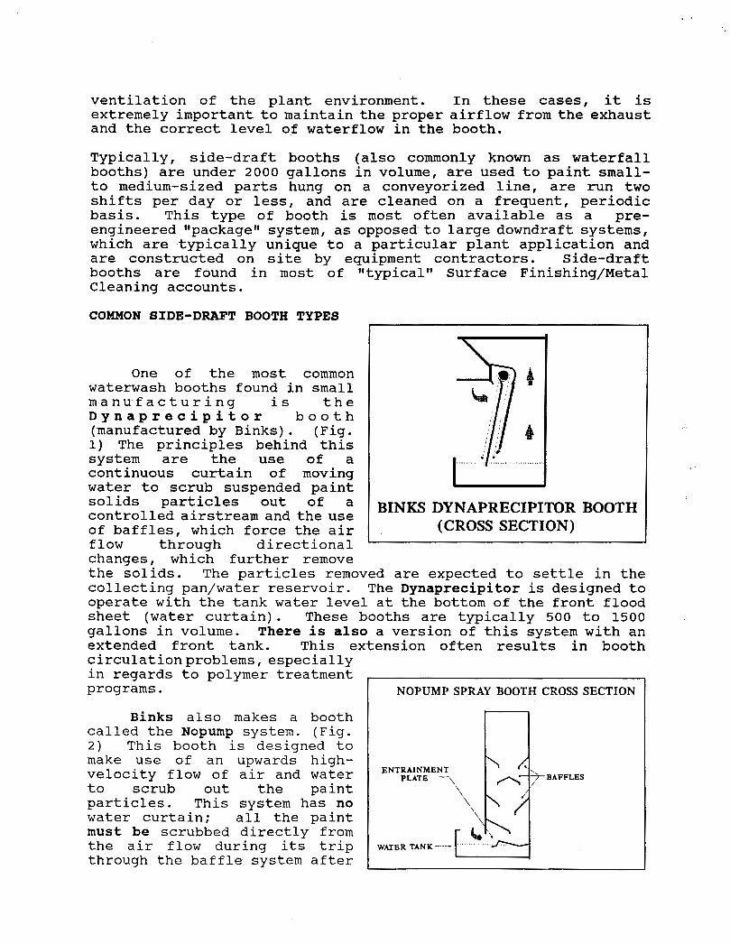
Another common model of sidedraft booth is the Turboclean booth (manufactured by Devilbiss). This type relies upon a standard continuous water curtain as well as an air-wash area consisting of a series of spray nozzles and baffles in the rear section. In addition, hot- visible in the diagram, is another feature unique to the Turboclean - the Venturi cone. This is a funnel-shaped device located in the front tank of the booth used to pull any floating materials from the surface of the tank to distribute them to the bottom. The mixing action of the venturi cone helps to circulate the surrounding area of the tank, resulting in good overall circulation of the tank.
DeVilbiss also markets a pumpless booth, called the Dynaclean. (Fig. 3) As can be
DEVILBISS DYNACLEAN BOOTH (PUMPLESS) -
.........
seen from the diagram, this booth, unlike the Binks model, does have a water curtain. The tank water is pulled up through the air wash chamber where the scrubbing takes place. It is then returned to the spill trough to recascade down the water curtain. This system may have slightly better tank mixing than the Binks, but nay still require the use of auxiliary circulation equipment to maintain the tank.
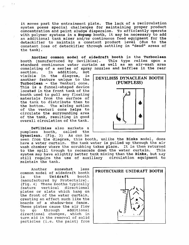
Another somewhat less common model of sidedraft booth is the Unidraft booth (manufactured by Protectaire) . (Fig. 4 ) These booths typically feature vertical directional plates or slats which hang on the front of the water curtain, creating an effect much like the boards of a shadow-box fence. These plates cause the air flow to go through additional directional changes, which in turn aid in the removal of solid particles (i.e. the paint) from
PROTECTAIRE UNIDRAFT BOOTH
the air. One common Occurrence with these slats is for paint solids to build up on scratches and nicks on the slat edges. Since this will eventually impede air-flow, it is important to keep these slats as clean as possible at all times.
In addition to the Unidraft, Protectaire also markets lfconventionalff systems, like Binks and DeVilbiss. Their standard water-wash booths have a curved waterfall wall/floodsheet and a set of nozzles behind the water curtain for additional solids removal.
custom-designed f o r particular applications and facilities by
DOWNDRAFT SYSTEMS
HADIN HYDROSPIN D O W N D R A ~ BOOTH
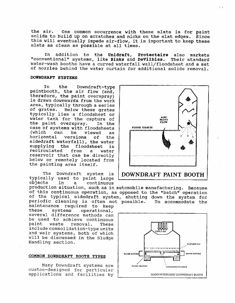
In the Downdraft-type paintbooth, the air flow (and, therefore, the paint overspray) is drawn downwards from the work area, typically through a series of grates. Below these grates typically lies a floodsheet or water tank for the capture of the paint overspray. In the case of systems with floodsheets (which can be viewed as horizontal versions of the sidedraft waterfall), the water supplying the floodsheet is recirculated from a water reservoir that can be directly below or remotely located from the painting area itself.
typically used to paint large I objects - in a continuous production situation, such as in automobile manufacturing. Because of this continuous operation, as opposed to the I1batchf1 operation of the typical sidedraft system, shutting down the system for Deriodic cleaninq is often not possible. To accommodate the maintenance required to keep these systems operational, several difference methods can be used to achieve continuous paint waste removal. These includeconsolidation-typeunits and weir systems, both of which will be discussed in the Sludge Handling section.
COMMON DOWNDRAFT BOOTH TYPES
SUWLY AIR m FLOODED PAN I..--- _.-_.- -.--.--.--.-
-fl I WATERREIURN
HYDROSPIN CYIJNlJER
/ Many Downdraft systems are I FLOOR GRATING
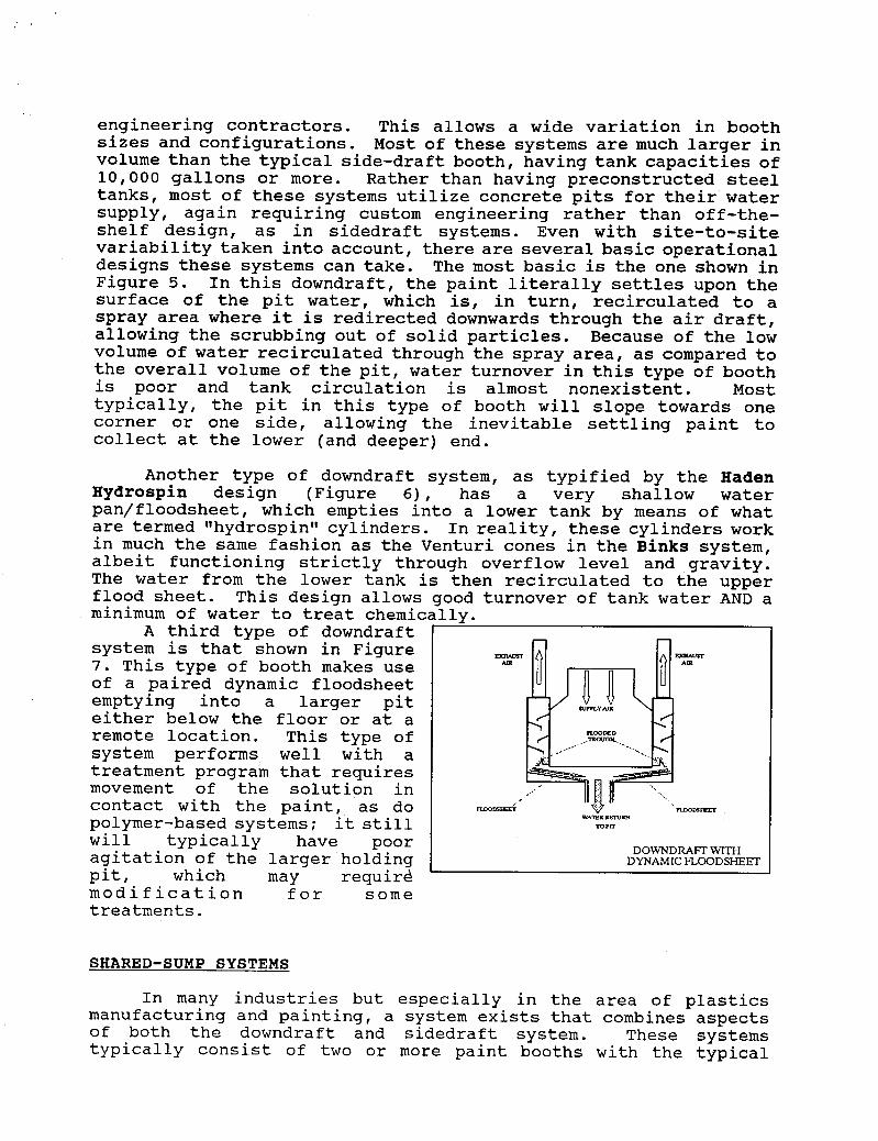
engineering contractors. This allows a wide variation in booth sizes and configurations. Most of these systems are much larger in volume than the typical side-draft booth, having tank capacities of 10,000 gallons or more. Rather than having preconstructed steel tanks, most of these systems utilize concrete pits for their water supply, again requiring custom engineering rather than off-the- shelf design, as in sidedraft systems. Even with site-to-site variability taken into account, there are several basic operational designs these systems can take. The most basic is the one shown in Figure 5. In this downdraft, the paint literally settles upon the surface of the pit water, which is, in turn, recirculated to a spray area where it is redirected downwards through the air draft, allowing the scrubbing out of solid particles. Because of the low volume of water recirculated through the spray area, as compared to the overall volume of the pit, water turnover in this type of booth
Most is poor and tank circulation is almost nonexistent. typically, the pit in this type of booth will slope towards one corner or one side, allowing the inevitable settling paint to collect at the lower (and deeper) end.
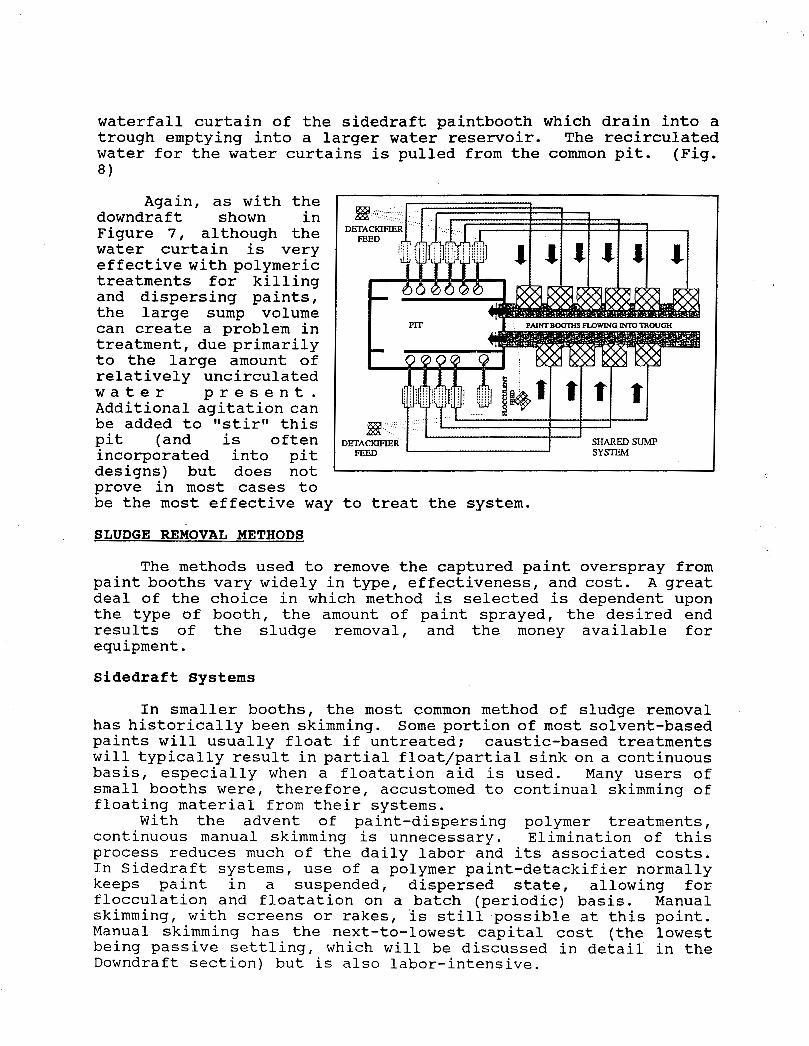
A third type of downdraft system is that shown in Figure 7. This type of booth makes use of a paired dynamic floodsheet emptying into a larger pit either below the floor or at a remote location. This type of system performs well with a treatment program that requires movement of the solution in contact with the paint, as do polymer-based systems; it still will typically have poor agitation of the larger holding
ExRum Bauvrr Am An
F u a m w ; WAlEK ElUm
ram
DOWNDRAFT WITH DYNAMIC FLOODSHEET
SHARED-SUMP SYSTEMS
In many industries but especially in the area of plastics manufacturing and painting, a system exists that combines aspects of both the downdraft and sidedraft system. These systems typically consist of two or more paint booths with the typical
waterfall curtain of the sidedraft paintbooth which drain into a trough emptying into a larger water reservoir. The recirculated water for the water curtains is pulled from the common pit. (Fig. 8 )
Again, as with the downdraft shown in Figure 7, although the water curtain is very effective with polymeric treatments for killing and dispersing paints, the large sump volume can create a problem in treatment, due primarily to the large amount of relatively uncirculated w a t e r p r e s e n t . Additional agitation can be added to Itstir" this pit (and is often incorporated into pit designs) but does not prove in most cases to
D
be the most effective way to treat the system.
SLUDGE REMOVAL METHODS
The methods used to remove the captured paint overspray from paint booths vary widely in type, effectiveness, and cost. A great deal of the choice in which method is selected is dependent upon the type of booth, the amount of paint sprayed, the desired end results of the sludge removal, and the money available for equipment.
Sidedraft Systems
In smaller booths, the most common method of sludge removal has historically been skimming. Some portion of most solvent-based paints will usually float if untreated: caustic-based treatments will typically result in partial float/partial sink on a continuous basis, especially when a floatation aid is used. Many users of small booths were, therefore, accustomed to continual skimming of floating material from their systems.
With the advent of paint-dispersing polymer treatments, continuous manual skimming is unnecessary. Elimination of this process reduces much of the daily labor and its associated costs. In Sidedraft systems, use of a polymer paint-detackifier normally keeps paint in a suspended, dispersed state, allowing for flocculation and floatation on a batch (periodic) basis. Manual skimming, with screens or rakes, is still possible at this point. Manual skimming has the next-to-lowest capital cost (the lowest being passive settling, which will be discussed in detail in the Downdraft section) but is also labor-intensive.
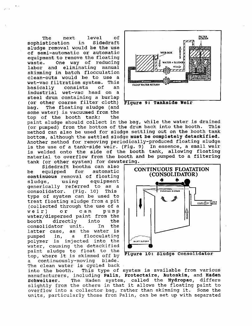
The next level of sophistication in Sidedraft sludge removal would be the use of semi-automatic or automatic equipment to remove the floating waste. One way of reducing labor and eliminating manual skimming in batch flocculation clean-outs would be to use a wet-vac filtration system. This basically consists of an industrial wet-vac head on a steel drum containing a burlap (or other coarse filter cloth) bag. The floating sludge (and some water) is vacuumed from the top of the booth tank; the
F I L E R SCREEN
igure 9: Tankside Weir
paint sludge should collect in the bag, while the water is drained (or pumped) from the bottom of the drum back into the booth. This method can also be used for sludge settling out on the booth tank bottom, although the settled sludge must be completely detackified. Another method for removing periodically-produced floating sludge is the use of a tank-side weir. (Fig. 9) In essence, a small weir is welded onto the side of the booth tank, allowing floating material to overflow from the booth and be pumped to a filtering tank (or other system) for dewaterins.
Sidedraft booths- can also be equipped for automatic continuous removal of floating sludge, using equipment generically referred to as a consolidator. (Fig. 10) This type of system can be used to treat floating sludge from a pit (collected through the use of a
water/dispersed paint from the booth directly into the consolidator unit. In the latter case, as the water is pumped in, a flocculating polymer is injected into the water, causing the detackified paint sludge to float to the top, where it is skimmed off by a continuously-moving blade. The clean water is cvcled back
w e i r ) o r c a n P u m p
CONTINUOUS FLOATATION (CONSOLIDATOR)
'igure 10: Sludge Consolidator
into the booth. Thcs type of system is available from various manufacturers, including Palin, Brotectaire, Autoskim, and Haden Schweitzer. The Haden system, called the Hydropac, differs slightly from the others in that 'it allows the floating paint to overflow into a collector bag, rather than skimming it. Some the units, particularly those from Palin, can be set up with separated
compartments, allowing skimming of different booths with the same equipment.
Paint sludge can also be removed continuously without flocculation/floating using filtration methods. The simplest filtration equipment consists of filter beds utilizing paper or cloth media. These systems allow the solid material to settle out on the filter media, with the water draining to some collection unit where it can be returned to the booth. Although this type of system has low labor and capital requirements, it is often very cumbersome, which can be a problem since space around a painting area is ususally at a premium. Gravity filtration systems are also slow and restricted as to throughput volume, which makes them suitable for only low levels of water or sludge to be processed. Vacuum filtration, such as that done using diatomaceous earth filters, is effective on completely-detackified materials, but can add to the overall volume of waste produced due to the contributions of the disposable media il
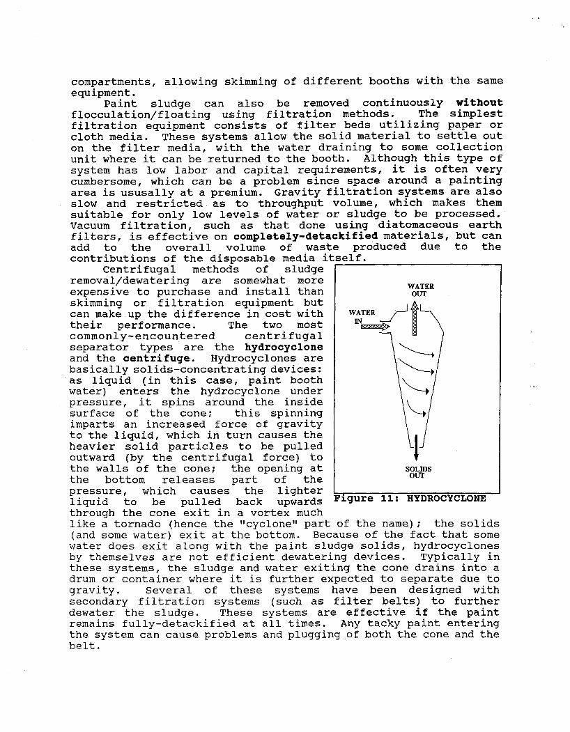
Centrifugal methods of sludge removal/dewatering are somewhat more expensive to purchase and install than skimming or filtration equipment but can make up the difference in cost with their performance. The two most commonly-encountered centrifugal separator types are the hydrocyclone and the centrifuge. Hydrocyclones are basically solids-concentrating devices: as liquid (in this case, paint booth water) enters the hydrocyclone under pressure, it spins around the inside surface of the cone: this spinning imparts an increased force of gravity to the liquid, which in turn causes the heavier solid particles to be pulled outward (by the centrifugal force) to the walls of the cone: the opening at the bottom releases part of the pressure, which causes the lighter liquid to be pulled back upwards throuqh the cone exit in a vortex much
;elf.
WATER OUT
SOLIDS OUT
igure 11: HYDROCYCLONE
like a tornado (hence the llcyclonetl part of the name); the solids (and some water) exit at the bottom. Because of the fact that some water does exit along with the paint sludge solids, hydrocyclones by themselves are not efficient dewatering devices. Typically in these systems, the sludge and water exiting the cone drains into a drum or container where it is further expected to separate due to gravity. Several of these systems have been designed with secondary filtration systems (such as filter belts) to further dewater the sludge. These systems are effective if the paint remains fully-detackified at all times. Any tacky paint entering the system can cause problems and plugging of both the cone and the belt.
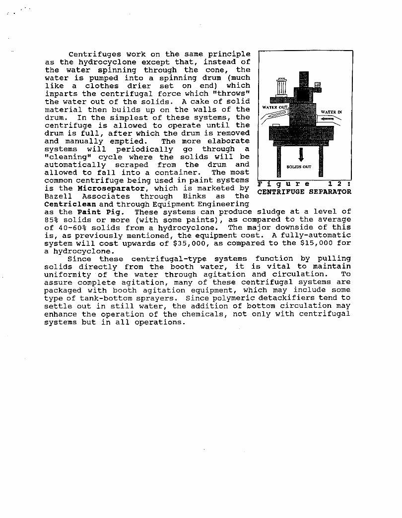
Centrifuges work on the same principle as the hydrocyclone except that, instead of the water spinning through the cone, the water is pumped into a spinning drum (much like a clothes drier set on end) which imparts the centrifugal force which llthrowslt the water out of the solids. A cake of solid material then builds up on the walls of the drum. In the simplest of these systems, the centrifuge is allowed to operate until the drum is full, after which the drum is removed and manually emptied. The more elaborate systems will periodically go through a "cleaningff cycle where the solids wilI be automatically scraped from the drum and allowed to fall into a container. The most common centrifuge being used in paint systems
SOLJDS OUT
' i g u r e 1 2 : is the Microseparator, which is marketed by Bazell Associates through Binks as the Centriclean and through Equipment Engineering as the Paint Pig. These systems can produce sludge at a level of 85% solids or more (with some paints), as compared to the average of 40-60% solids from a hydrocyclone. The major downside of this is, as previously mentioned, the equipment cost. A fully-automatic system will cost upwards of $35,000, as compared to the $15,000 for a hydrocyclone.
Since these centrifugal-type systems function by pulling solids directly from the booth water, it is vital to maintain uniformity of the water through agitation and circulation. To assure complete agitation, many of these centrifugal systems are packaged with booth agitation equipment, which may include some type of tank-bottom sprayers. Since polymeric detackifiers tend to settle out in still water, the addition of bottom circulation may enhance the operation of the chemicals, not only with centrifugal systems but in all operations.
CENT~IFUGE