waukee - united process...
TRANSCRIPT

Waukee Compressor
User Manual – revision 2

Waukee Compressor – Rev 2 Page 2
Copyright © 2013, United Process Controls Inc. All rights to copy, reproduce and transmit are reserved
Manual #: 014 Rev No: 2 Date: 26 Mar 2013
COPYRIGHT No part of this publication may be reproduced, transmitted, transcribed, stored in a retrieval system, or translated into any language or computer language, in any form or by any means, electronic, mechanical, magnetic, optical, chemical, manual, or otherwise, without prior written permission of United Process Controls Inc.
DISCLAIMER:
The Waukee Compressor is to be used by the industrial operator under his/her direction. Waukee Engineering is not responsible or liable for any product, process, damage or injury incurred while using the Waukee Compressor. United Process Controls Inc. makes no representations or warranties with respect to the contents hereof and specifically disclaim any implied warranties or merchantability or fitness for any particular purpose.
For assistance please contact: United Process Controls Inc.
TEL: +1-414-462-8200 • FAX: +1-414-462-7022
Toll free North America: +1-800-438-3347
www.group-upc.com

Waukee Compressor – Rev 2 Page 3
Copyright © 2013, United Process Controls Inc. All rights to copy, reproduce and transmit are reserved
WARNING
Thank you for purchasing equipment from Waukee Engineering a member of United Process Controls. We want your new equipment to operate safely. Anyone who uses this equipment should read this publication (and any other relevant publications) before installing or operating the equipment. To minimize the risk of potential safety problems, you should follow all applicable local and national codes that regulate the installation and operation of your equipment. These codes vary from area to area and usually change with time. It is your responsibility to determine which codes should be followed, and to verify that the equipment, installation, and operation are in compliance with the latest version of these codes. At a minimum, you should follow all applicable sections of the National Fire Code, National Electrical Code, and codes of the National Electrical Manufacture’s Association (NEMA). There may be local regulatory or government offices that can also help determine which codes and standards are necessary for safe installation and operation. Equipment damage or serious injury to personnel can result from failure to follow all applicable codes and standards. We do not guarantee the products described in this publication are suitable for your particular application, nor do we assume any responsibility for you product design, installation, or operation. If you have any questions concerning the installation or operation of this equipment, or if you need additional information, please call us at 414-462-8200
WARNING: Read this manual thoroughly before using Compressor.
CAUTION

Waukee Compressor – Rev 2 Page 4
Copyright © 2013, United Process Controls Inc. All rights to copy, reproduce and transmit are reserved
TABLE OF CONTENTS
WARNING .......................................................................................................................................................................................... 3
1. INTRODUCTION ........................................................................................................................................................................ 5
2. IMPORTANT SAFETY INFORMATION ......................................................................................................................................... 6
3. TURNDOWN ............................................................................................................................................................................. 6
4. DESCRIPTION ............................................................................................................................................................................ 7
5. SPECIFICATIONS........................................................................................................................................................................ 8
5.1 Compressor .................................................................................................................................................................................. 8
5.2 Serial Number .............................................................................................................................................................................. 9
6. INSTALLATION ........................................................................................................................................................................ 10
6.1 Mounting ................................................................................................................................................................................... 10
6.2 Wiring Guidelines ....................................................................................................................................................................... 10
6.3 Wiring ........................................................................................................................................................................................ 10
6.4 V-Belt ......................................................................................................................................................................................... 11
7. BYPASS RELIEF ........................................................................................................................................................................ 12
7.1 Internal built-in Unloader .......................................................................................................................................................... 12
7.2 External Relief Regulator ........................................................................................................................................................... 12
8. MAINTENANCE ....................................................................................................................................................................... 12
8.1 Recommended Scheduled Maintenance ................................................................................................................................... 13
8.2 Recommended Spare Parts: ....................................................................................................................................................... 13
8.3 Vane and Bearing Replacement (Refer to Appendix “D” – Parts List) .................................................................................. 14
8.4 Unloader Diaphragm Replacement: .......................................................................................................................................... 15
9. TROUBLESHOOTING ............................................................................................................................................................... 16
10. APPENDIX “A” - DRAWINGS .................................................................................................................................................... 17
11. APPENDIX “B” - CAPACITY TABLE ............................................................................................................................................ 18
12. APPENDIX “C” - PARTS LIST ..................................................................................................................................................... 19
Waukee Warranty Policy, Disclaimer and Limitation of Liability ...................................................................................................... 21

Waukee Compressor – Rev 2 Page 5
Copyright © 2013, United Process Controls Inc. All rights to copy, reproduce and transmit are reserved
1. INTRODUCTION
The Purpose of this Manual
Thank You for purchasing a Waukee Compressor. This manual shows you how to install and maintain Waukee’s Compressor. This manual contains important information and should be read and understood by all individuals who install, use or service this equipment.
Supplemental Manuals
The Waukee Carburetor manual contains technical information as well as precautions regarding use of Waukee’s Carburetor with a Waukee Compressor.
Technical Support
We strive to make our manuals the best in the industry. We rely on your feedback to let us know if we are reaching our goal. If you cannot find the solution to your particular application, or, if for any reason you need technical assistance, please call us at:
+1-414-462-8200 Toll free North America: +1-800-438-3347
Our technical support group will work with you to answer your questions. They are available Monday through Friday from 8:00 A.M. to 4:30 P.M. Central Standard Time. We also encourage you to visit our web site where you can find technical and non-technical information about our products and company.
www.group-upc.com
If you have a comment, question or suggestion about any of our products, services, or manuals, please e-mail or contact us by phone.
Conventions Used
When you see the “exclamation point” icon in the left-hand margin, the paragraph to its immediate right will be a warning. This information could prevent injury, loss of property, or even death in extreme cases. Any warning in this manual should be regarded as critical information that should be read in its entirety. The word WARNING or CAUTION in boldface will mark the beginning of the text.
CAUTION

Waukee Compressor – Rev 2 Page 6
Copyright © 2013, United Process Controls Inc. All rights to copy, reproduce and transmit are reserved
CAUTION
2. IMPORTANT SAFETY INFORMATION
Waukee Engineering Company, Inc. Compressors, Gas Boosters and Air/Gas Mixors™ are not warranted or specified to meet the building or gas handling codes of any specific jurisdiction. In particular, certain codes state that gas-handling equipment in certain applications must be “leak tight”. Waukee Engineering equipment does not meet the definition of “leak tight”. Similarly, Waukee Engineering equipment does not meet the requirements of codes, which require “hermetically sealed” compressors for certain applications. It is the responsibility of purchasers of Waukee Engineering equipment to determine the suitability of our equipment for a particular use and to determine the requirements of any codes, which apply, to the customer’s proposed application. Waukee Engineering cannot be responsible for any accidents, which occur from incorrectly specifying Waukee Engineering equipment. Waukee Engineering Compressors are designed solely for industrial applications installed in well-ventilated, non-classified locations only. The equipment should not be installed or used in residential, institutional, office or other non-industrial, commercial applications. Failure to properly specify, install and ventilate Waukee Engineering equipment can result in serious accidents causing injury and even death.
3. TURNDOWN
It is recommended that Waukee Compressors and Mixors be limited to a turn down range of 50% the total rated output. During short periods of time it is allowable to run the Compressor below this flow rate. However, if extended operation is expected below the flow rate of 50% of rated output the Compressor / Mixor should be fitted with an external bypass regulation system and either a heat exchanger or Waukee CPC (Compressor Pressure Controller). These devices reduce the amount of wear to the compressor vanes by eliminating heat build-up. Primarily, excessive heat build-up and improper lubrication diminish the life of a compressor vane.
WARNING: Running a Compressor below 50% of rated output for extended amounts
of time will dramatically reduce the life of the compressor vanes and result in poor
performance.

Waukee Compressor – Rev 2 Page 7
Copyright © 2013, United Process Controls Inc. All rights to copy, reproduce and transmit are reserved
4. DESCRIPTION
Waukee Compressors are designed to be easy to maintain and service so that down time is kept to a minimum. These units have a simple, compact design with minimal moving parts and are available in a wide range of sizes with capacities from 200 CFH to 12,000 CFH and outlet pressures up to 3 psig. Waukee Compressors contain a 6-vane rotor which is supported at both ends by factory sealed and lubricated ball bearings and operate at an acceptably low noise level (90 DbA at a distance of 2 feet from Compressor). Since Waukee compressors do not contain any gears, springs, or metal contacts there is less likelihood of failure. The low-friction vanes slide in and out of the rotor slots centrifugally. The Waukee closed-loop unloader maintains preset discharge pressure within commercially acceptable limits and saves time and money on installation by eliminating extra expense of an external relief valve and associated piping.
Note: The maximum allowable turndown of output volume for a standard Waukee Compressor is 50% of rated flow. If flow rates lower than 50% of ratings are anticipated, the compressor should be fitted with a Waukee CPC (Compressor Pressure Controller) Waukee offers a series of options for its compressors, which allow it to be built to your specific needs. These options include:
A pressure relief regulator for pressures below .5psig and above 2psig.
A CPC (Compressor Pressure Controller) to reduce costs of unused resources.
Automatic lubricator for phenolic vane compressors.
Available in 4 different configurations: (Refer to Specifications for descriptions)
Stand Alone Compressor - Includes the compressor with drive sheave only.
Booster - Includes compressor, motor, vertical or horizontal mounting base, drive sheaves and safety belt guard.
Mixor - Includes compressor, motor, vertical or horizontal mounting base, drive sheaves, belt guard, air filter, carburetor with gas-balancing regulator all mounted to a base and piped.
Flush Panel - Includes compressor, explosion proof motor, drive sheaves, belt guard, air filter, carburetor with gas balancing regulator mounted to a base and flush panel all piped from the factory.
3 different types of vanes available:
Carbon Vanes – Require no lubrication, short life span
Phenolic Vanes – Requires lubrication, good life span
Composite Vanes – Require No lubrication, longer life span then carbon vanes

Waukee Compressor – Rev 2 Page 8
Copyright © 2013, United Process Controls Inc. All rights to copy, reproduce and transmit are reserved
5. SPECIFICATIONS
5.1 Compressor
Min. Outlet Pressure: .5psig (3.4kPa) Min. Inlet Pressure: 0psig (0kPa) Max Outlet Pressure: 3psig (20.7kPa)* Max Inlet Pressure: 1psig (6.9kPa)*
Min Temperature: 32F (0C) ** Max Temperature: 150F (65C) **
ABC Series Compressors Inlet/Outlet Connections: ¾”NPT Motor Horse Power: 1/2HP, 3/4HP Max RPM: 950 Min RPM: 200 Max Output Volume: 600CFH (17M3H)
HJE Series Compressors Inlet/Outlet Connections: 1¼” NPT Motor Horse Power: 3/4HP, 1HP, 1.5HP, 2HP Max RPM: 1200 Min RPM: 250 Max Output Volume: 1,500CFH (42.5M3H)
FGN Series Compressors
Inlet/Outlet Connections: 2” NPT Motor Horse Power: 1.5HP, 2HP, 3HP Max RPM: 950 Min RPM: 300 Max Output Volume: 4,000CFH (113.3M3H)
RSUW Series Compressors
Inlet/Outlet Connections: 3” NPT Motor Horse Power: 3HP, 5HP, 7.5HP Max RPM: 950 Min RPM: 350 Max Output Volume: 8,000CFH (226.5M3H)
XYZ Series Compressors
Inlet/Outlet Connections: 3” NPT Motor Horse Power: 5HP, 7.5HP Max RPM: 950 Min RPM: 400 Max Output Volume: 12,000CH (339.8M3H)
* Consult with Waukee Engineering for higher pressures ** Consult with Waukee Engineering for different operating temperatures
Waukee Compressor – Rev 2 Page 9
Copyright © 2013, United Process Controls Inc. All rights to copy, reproduce and transmit are reserved
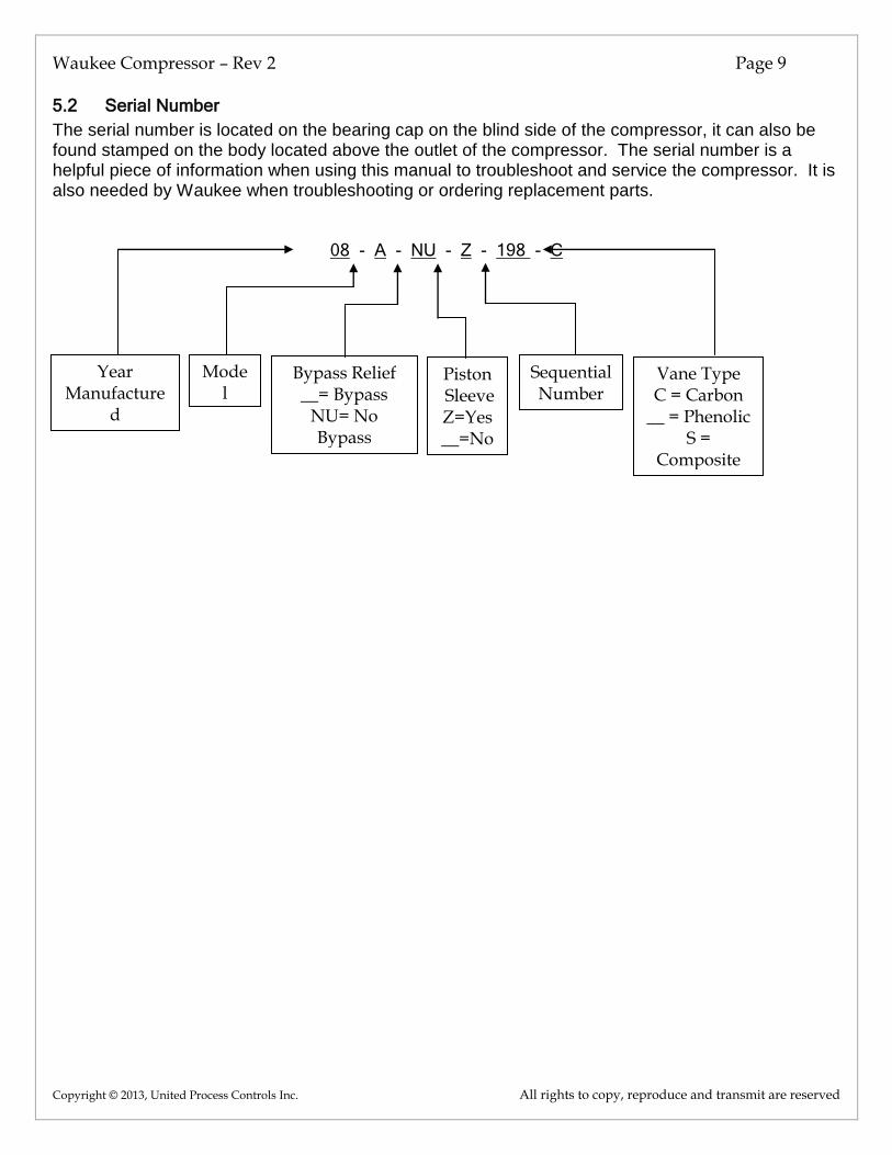
5.2 Serial Number
The serial number is located on the bearing cap on the blind side of the compressor, it can also be found stamped on the body located above the outlet of the compressor. The serial number is a helpful piece of information when using this manual to troubleshoot and service the compressor. It is also needed by Waukee when troubleshooting or ordering replacement parts.
08 - A - NU - Z - 198 - C
Year Manufacture
d
Model
Bypass Relief __= Bypass
NU= No Bypass
Piston Sleeve Z=Yes __=No
Sequential Number
Vane Type C = Carbon
__ = Phenolic S =
Composite
Waukee Compressor – Rev 2 Page 10
Copyright © 2013, United Process Controls Inc. All rights to copy, reproduce and transmit are reserved
CAUTION
6. INSTALLATION
6.1 Mounting
Remove the unit from its packaging. If the compressor is equipped with an integrated unloader, remove unloader cover and remove any packaging material that may be used to protect the unloader during shipment. Then position and securely mount the unit in the desired location, for hole pattern dimensions refer to Appendix “A” – Drawings.
6.2 Wiring Guidelines
Your company may have guidelines for wiring installation. If so, you should check those before you begin the installation. Here are some general things to consider:
Use the shortest wiring route whenever possible.
Route the wiring through an approved cable housing to minimize the risk of accidental damage. Check local and national codes to choose the correct method for your application.
CAUTION: To reduce the risk of electrical shock and also to prevent
damage to the Compressor. It is advised to turn off the supply power
before connecting or disconnecting any wires.
6.3 Wiring
Wire the motor to the proper voltage according to the instructions on the motor. Motors provided by Waukee can be wired for either standard 190/380VAC (Low Voltage) or 230/460VAC (High Voltage), 50/60Hz, 3 phase power. 1725-1750 RPM unless special voltages or other characteristics are specified in the order. Wire the motor through a motor starter. See Appendix B “Capacity Table”, regarding the ratings of the motor for your size Waukee Compressor. If your compressor is equipped with a Waukee Automatic Lubricator, refer to the manual for Waukee’s Automatic Lubricator for proper wiring.
WARNING: DO NOT install the V- belt until the rotation of the motor is verified. If
the motor spins the compressor in the wrong direction it will damage the vanes in
the compressor and will require rebuilding the compressor.
To verify the proper rotation of the motor with the V- belt removed, apply power to the motor and verify that it is spinning in the direction as indicated on the side of the compressor. If the motor is not spinning in the proper direction, reverse two of the wires on the motor and repeat the test until the motor is spinning in the correct direction.
CAUTION
Waukee Compressor – Rev 2 Page 11
Copyright © 2013, United Process Controls Inc. All rights to copy, reproduce and transmit are reserved
6.4 V-Belt
CAUTION: Before performing maintenance of tensioning on the belt, turn
equipment off and lock out the power source. Use belt guards on compressor
when running.
Proper tension is the key to long, efficient, trouble-free operation. When you install a new belt, use a v-belt tension gauge to establish correct tension. Then to maintain performance, check belt tension on a regular basis. The payoff is maximum belt life, reduced downtime, and uninterrupted equipment service.
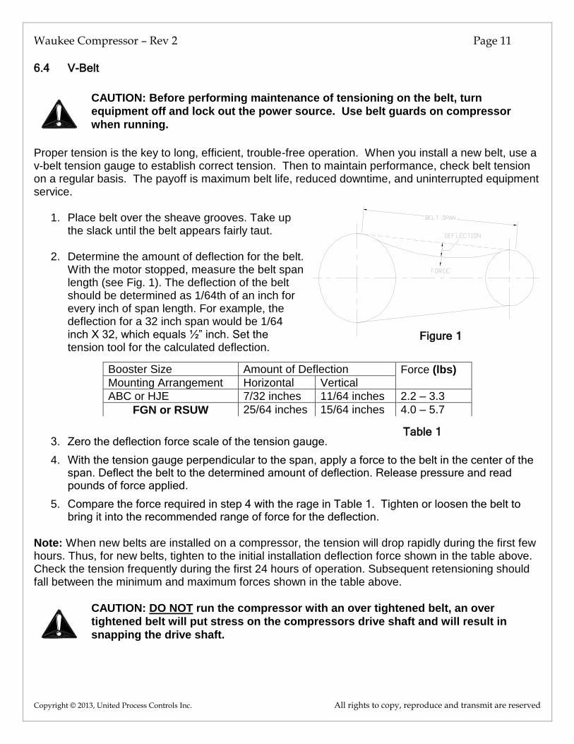
1. Place belt over the sheave grooves. Take up the slack until the belt appears fairly taut.
2. Determine the amount of deflection for the belt. With the motor stopped, measure the belt span length (see Fig. 1). The deflection of the belt should be determined as 1/64th of an inch for every inch of span length. For example, the deflection for a 32 inch span would be 1/64 inch X 32, which equals ½” inch. Set the tension tool for the calculated deflection.
3. Zero the deflection force scale of the tension gauge.
4. With the tension gauge perpendicular to the span, apply a force to the belt in the center of the span. Deflect the belt to the determined amount of deflection. Release pressure and read pounds of force applied.
5. Compare the force required in step 4 with the rage in Table 1. Tighten or loosen the belt to bring it into the recommended range of force for the deflection.
Note: When new belts are installed on a compressor, the tension will drop rapidly during the first few hours. Thus, for new belts, tighten to the initial installation deflection force shown in the table above. Check the tension frequently during the first 24 hours of operation. Subsequent retensioning should fall between the minimum and maximum forces shown in the table above.
CAUTION: DO NOT run the compressor with an over tightened belt, an over
tightened belt will put stress on the compressors drive shaft and will result in
snapping the drive shaft.
Booster Size Amount of Deflection Force (lbs) Mounting Arrangement Horizontal Vertical
ABC or HJE 7/32 inches 11/64 inches 2.2 – 3.3
FGN or RSUW 25/64 inches 15/64 inches 4.0 – 5.7
CAUTION
Figure 1
CAUTION
Table 1

Waukee Compressor – Rev 2 Page 12
Copyright © 2013, United Process Controls Inc. All rights to copy, reproduce and transmit are reserved
7. BYPASS RELIEF
Depending on your application Waukee Compressors are sold with two types of bypass relief. For pressures between .5psig (3.5kPa) – 2.5psig (17.2kPa) the compressor is equipped with an integrated built-in unloader. For pressures below .5psig (3.5kPa) or above 2.5psig (17.2kPa) the compressor is equipped with an external relief regulator. The bypass relief is set at the factory to the specifications provided when ordered.
7.1 Internal built-in Unloader
To change the output pressure of compressors equipped with the integrated unloader will require the removal of weight to decrease the pressure and addition of weight to increase the pressure. Additional weights are available from Waukee if
needed. Refer to Figure 2. NOTE: Compressors equipped with the built-in unloader are only capable of pressure ranges between .5psig (3.5kPa) – 2.5psig (17.2kPa) if outlet pressures above or below are needed, contact Waukee about changing the integrated unloader to an external relief regulator.
7.2 External Relief Regulator
To change the output pressure of compressors equipped with an external relief regulator will require adjustment of the spring. To increase the pressure screw the spring in, to decrease
the pressure screw the spring out. Note: depending on the outlet pressure required a different spring may be needed to achieve the desired outlet pressure. Refer to Tables 2 & 3 for spring color pressure ranges.
Type 289L Regulator
Spring
Color
Pressure Range
Dark Blue 7 to 18” wcg (1.7 to 4.5kPa)
Gray .5 to 2.25psig (3.4 to 15.5kPa)
Dark Green 1.75 to 7psig (12 to 48.3kPa)
Type 289H Regulator
Spring
Color
Pressure Range
Silver 12 to 40” wcg (3 to 10kPa)
Pink 1 to 4.5psig (6.9 to 31kPa)
Figure 2
Figure 4 Type 289L
Table 3
Table 2
Figure 3 Type 289H
Table 3

Waukee Compressor – Rev 2 Page 13
Copyright © 2013, United Process Controls Inc. All rights to copy, reproduce and transmit are reserved
CAUTION
8. MAINTENANCE
8.1 Recommended Scheduled Maintenance
CAUTION: Before performing any maintenance, turn equipment off and lock out the
power source. Use belt guards on compressor when running.
Once a week: 1. If unit is equipped with an Automatic Lubricator fill oil reservoir with Waukee compressor oil
and check to make sure it is operating properly. Refer to Automatic Lubricator Manual #3250
2. If equipped with an air filter, remove the filter and clean by blowing compressed air through
filter from the inside and replace if needed. DO NOT OIL FILTER CARTRIDGE.
Once a month: 1. Check tension of the belt. If belt is too loose or badly worn, tighten belt or replace.
2. If unit is equipped with an unloader check to see if the movement of the piston is restricted.
Clean piston if necessary, refer to diaphragm replacement for instructions on assembly of the unloader. (Dirty plant air may require this part to be cleaned monthly.)
Once a Year: 1. Shut down equipment and disassemble compressor to inspect the vanes and bearings. The
life of the bearings and vanes is dependent on the operating conditions and the usage. Replace vanes and bearings if they appear to be worn. To prevent emergency break downs, it is recommended that the vanes and bearings be replaced.
8.2 Recommended Spare Parts:
To reduce down time in the event of a compressor failure, Waukee recommends having the following spare parts on hand: Set of 6 Vanes, Gasket Kit, Unloader Diaphragm gasket kit, Waukee Compressor Oil and spare V-Belt. When ordering spare parts please have the serial number of the compressor the spare parts will be for.
NOTICE: Waukee’s rotor vanes are precision parts carefully manufactured to exact tolerances. When spare vanes are ordered, the vanes are manufactured to fit the serial number of the
compressor they are ordered for ONLY!!
WARNING: DO NOT use vanes ordered for a specific serial number
compressor in another compressor, the vanes may not fit properly and may
result in damage to the vanes and/or compressor.
CAUTION
Waukee Compressor – Rev 2 Page 14
Copyright © 2013, United Process Controls Inc. All rights to copy, reproduce and transmit are reserved
CAUTION
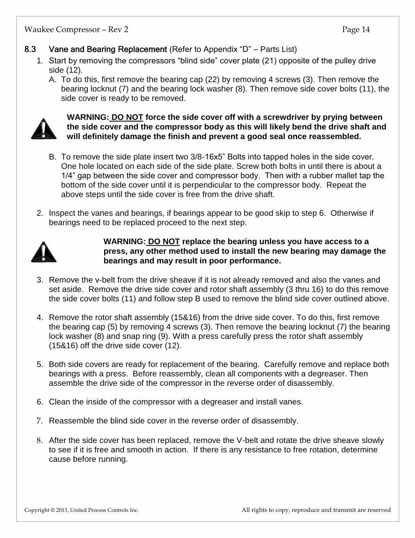
8.3 Vane and Bearing Replacement (Refer to Appendix “D” – Parts List)
1. Start by removing the compressors “blind side” cover plate (21) opposite of the pulley drive side (12). A. To do this, first remove the bearing cap (22) by removing 4 screws (3). Then remove the
bearing locknut (7) and the bearing lock washer (8). Then remove side cover bolts (11), the side cover is ready to be removed.
WARNING: DO NOT force the side cover off with a screwdriver by prying between
the side cover and the compressor body as this will likely bend the drive shaft and
will definitely damage the finish and prevent a good seal once reassembled.
B. To remove the side plate insert two 3/8-16x5” Bolts into tapped holes in the side cover.
One hole located on each side of the side plate. Screw both bolts in until there is about a 1/4” gap between the side cover and compressor body. Then with a rubber mallet tap the bottom of the side cover until it is perpendicular to the compressor body. Repeat the above steps until the side cover is free from the drive shaft.
2. Inspect the vanes and bearings, if bearings appear to be good skip to step 6. Otherwise if
bearings need to be replaced proceed to the next step.
WARNING: DO NOT replace the bearing unless you have access to a
press, any other method used to install the new bearing may damage the
bearings and may result in poor performance.
3. Remove the v-belt from the drive sheave if it is not already removed and also the vanes and
set aside. Remove the drive side cover and rotor shaft assembly (3 thru 16) to do this remove the side cover bolts (11) and follow step B used to remove the blind side cover outlined above.
4. Remove the rotor shaft assembly (15&16) from the drive side cover. To do this, first remove the bearing cap (5) by removing 4 screws (3). Then remove the bearing locknut (7) the bearing lock washer (8) and snap ring (9). With a press carefully press the rotor shaft assembly (15&16) off the drive side cover (12).
5. Both side covers are ready for replacement of the bearing. Carefully remove and replace both bearings with a press. Before reassembly, clean all components with a degreaser. Then assemble the drive side of the compressor in the reverse order of disassembly.
6. Clean the inside of the compressor with a degreaser and install vanes.
7. Reassemble the blind side cover in the reverse order of disassembly.
8. After the side cover has been replaced, remove the V-belt and rotate the drive sheave slowly to see if it is free and smooth in action. If there is any resistance to free rotation, determine cause before running.
CAUTION

Waukee Compressor – Rev 2 Page 15
Copyright © 2013, United Process Controls Inc. All rights to copy, reproduce and transmit are reserved
8.4 Unloader Diaphragm Replacement:
Removal of Unloader (Refer to fig. 5) 1. Loosen the unloader cover by removing the screws that hold it into
place. 2. Remove the unloader cap and weights. 3. Loosen the bolts on hold down ring and remove the ring. 4. Lift out, as a complete assembly the unloader diaphragm and piston
assembly. 5. Loosen screws that hold the unloader sleeve and remove sleeve.
(Note: older units do not have an unloader sleeve) 6. Remove the unloader piston screw and discard this and the
diaphragm assembly. 7. Clean the piston, orifice and the chamber. Make sure the bleed hole in
the orifice is open.
Assembly for Compressors without Piston Sleeve (Refer to fig. 5)
1. Lightly oil the piston and insert into compressor. 2. Place gasket on top of compressor. 3. Insert Diaphragm assembly into compressor. 4. Place gasket and then hold down plate on top of diaphragm. 5. Install the bolts but Do Not secure them into place yet. 6. Remove the wrinkles from the diaphragm and gently raise the piston
to take up the slack in the diaphragm and then secure bolts. Caution: Do not stretch the diaphragm too far so as not to elongate the diaphragm holes.
7. If there are no leaks the piston should sink slowly and freely. 8. Re-install the unloader weights and the cover. 9. Return to normal operation.
Assembly for Compressors with Piston Sleeve (Refer to fig. 5)
1. Insert O-ring onto piston sleeve. 2. Insert piston sleeve into compressor. 3. Secure piston sleeve into place with screws. 4. Lightly oil the piston and insert into compressor. 5. Place gasket on top of compressor. 6. Insert diaphragm assembly into compressor. 7. Place gasket and then hold down plate on top of diaphragm. 8. Install the bolts but Do Not secure then into place yet. 9. Remove the wrinkles from the diaphragm and gently raise
the piston to take up the slack in the diaphragm and then secure bolts. Caution: Do not stretch the diaphragm too far so as not to elongate the diaphragm holes.
10. If there are no leaks the piston should sink slowly and freely. 11. Re-install the unloader weights and the cover. 12. Return to normal operation.
Figure 5

Waukee Compressor – Rev 2 Page 16
Copyright © 2013, United Process Controls Inc. All rights to copy, reproduce and transmit are reserved
9. TROUBLESHOOTING
The compressor should be operated only at the speed indicated on the Waukee nameplate located on the blind side of the compressor. If the compressor fails to produce the full rated capacity at the pressure specified on the nameplate, check the following:
1. Check to see if any valves upstream or downstream of the Waukee compressors are not fully open and causing a restriction in flow. Open any valves that may be causing the restriction.
2. If your system consists of a fire check, check to see if it is operating correctly and that it is clean. Measure the pressure drop across the fire check. It should only be a few “wcg” (inches Water Column Gauge). Clean, repair or replace the fire check if needed.
3. If all of the above points have been checked and the outlet pressure of the compressor still does provide the required flow and pressure as specified on the nameplate. Then there is a possibility that the vanes in the compressor have become dirty and gummed up causing them to become stuck in the rotor. To relieve this condition on lubricated compressors only, remove the oil connection from the oiler to the compressor and pour in about 3 table spoons of alcohol. (Alcohol will evaporate in the pipes downstream and will not cause clogging of the fire check or burners.) Turn on compressor for a few minutes to drain excess alcohol. Connect
oiler and start back in operation. DO NOT USE ALCOHOL IN NON-LUBE COMPRESSORS!!!
4. If the problem still persists then the compressor may require new vanes, refer to the Maintenance section of the manual for procedures for replacing the vanes.
PROBLEM
RECOMMENDED ACTION
Failure to compress
gas to full rated
output
Look for obstruction in line to unit being served such as a closed valve or dirty fire check. Use troubleshooting tips above. Check the unloader, the piston should move freely up and down. If the piston does not move freely, disassemble as outlined under MAINTENANCE and clean piston and bore with a mild degreaser. Dirty and sticking compressor vanes. Flush with alcohol as outlined under above.
Noisy Compressor
Chipped or broken rotor vanes. Inspect and replace if necessary as described in MAINTENANCE. Dirty and gummed up rotor vanes in compressor. Flush with alcohol as
outlined In Troubleshooting above (Note: Disregard for Non-lubricated type compressors.) Dirty piston in unloader. Disassemble unloader as outlined under MAINTENANCE and clean piston and bore with a mild degreaser and reassemble. Compressor Outlet deadheaded. (Do not operate the compressor for prolonged periods of time deadheaded. Doing so will result in overheating causing premature failure of the vanes and bearings).

Waukee Compressor – Rev 2 Page 17
Copyright © 2013, United Process Controls Inc. All rights to copy, reproduce and transmit are reserved
10. APPENDIX “A” - DRAWINGS
On Demand

Waukee Compressor – Rev 2 Page 18
Copyright © 2013, United Process Controls Inc. All rights to copy, reproduce and transmit are reserved
11. APPENDIX “B” - CAPACITY TABLE
WAUKEE COMPRESSOR AND BOOSTER CAPACITY TABLE
Compressor Model
Output Volume CFH [m3/h]
Output Pressure psig [kPa]
RPM HP/ kW
A
200 [5.66]
1 [6.89] 575
1/2 .373
2 [13.79] 600 3 [20.68] 650
B
400 [11.33]
1 [6.89] 650 2 [13.79] 725 3 [20.68] 800
C
600 [16.98]
1 [6.89] 850
3/4 .560
2 [13.79] 900
3 [20.68] 950
D
750 [21.23] 1 [6.89] 575 2 [13.79] 600 3 [20.68] 650
H
1000 [28.31]
1 [6.89] 850 1 .746 2 [13.79] 900
3 [20.68] 950 J
1250 [35.39]
1 [6.89] 1000
1.5 1.119
2 [13.79] 1050 3 [20.68] 1100
E
1500 [42.47]
1 [6.89] 1000 2 [13.79] 1050
3 [20.68] 1100
F
2000 [56.63] 1 [6.89] 550
2 1.492
2 [13.79] 575 3 [20.68] 600
G
3000 [84.94]
1 [6.89] 700 2 [13.79] 750 3 [20.68] 800
3 2.238
N
4000 [113.26]
1 [6.89] 875 2 [13.79] 900 3 [20.68] 950
R
5000 [141.58]
1 [6.89] 650 2 [13.79] 650 3 [20.68] 700
S
6000 [169.89]
1 [6.89] 760 2 [13.79] 780 3 [20.68] 800
5
3.730
U
7000 [198.21]
1 [6.89] 880 2 [13.79] 900 3 [20.68] 940
W
8000 [226.53]
1 [6.89] 1040 2 [13.79] 1060 3 [20.68] 1090

Waukee Compressor – Rev 2 Page 19
Copyright © 2013, United Process Controls Inc. All rights to copy, reproduce and transmit are reserved
12. APPENDIX “C” - PARTS LIST
* Parts only supplied as a matched set, ** only on compressors without a Bypass Relief *** only on compressors with a Bypass Relief Regulator

Waukee Compressor – Rev 2 Page 20
Copyright © 2013, United Process Controls Inc. All rights to copy, reproduce and transmit are reserved
Model ABC DHJE FGN RSUW
Item # P/N Qty. P/N Qty. P/N Qty. P/N Qty. Description
1 1-861 1 1-861 1 1-1921 1 1-1928 1 Drive Sheave 2 1-859 1 1-859 1 1-859 1 1-1927 1 Drive Sheave Key
3 1-860 8 1-860 8 1-860 12 1-860 12 Bearing Cap Screws
4 1-620 2 1-620 2 1-620 2 1-1069 2 Gas Seals
5 3-750 1 3-750 1 2-450 1 2-420 1 Drive Bearing Cap
6 1-425 2 1-425 2 1-972 2 1-972 2 Bearing Cap Gasket
7 1-615 2 1-615 2 1-615 2 1-1925 2 Bearing Lock Nut
8 1-616 2 1-616 2 1-616 2 1-1924 2 Bearing Lock Washer
9 1-1040 1 1-1040 1 1-1040 1 1-1075 1 Drive Bearing Snap Ring
10 1-623 2 1-623 2 1-623 2 1-1923 2 Rotor Shaft Bearing
11 1-856 16 1-856 16 1-1919 16 1-1919 16 Side Cover Bolt
12 1-1915 1 1-1915 1 1-1916 1 1-1917 1 Drive Side Cover
13 1-700 1 1-700 1 1-700 1 1-971 1 Rotor Spacer
14 1-858 Var. 1-858 Var. 1-858 Var. 1-1074 Var. Rotor Spacer Shims*
15 3-583 1 3-583 1 3-397 1 3-384 1 Rotor Shaft*
16 2-757 1 2-764 1 3-396 1 3-383 1 Rotor*
17 1-724 6 1-727 6 1-990 6 1-970 6 Phenolic Vanes
18 1-1017 6 1-1018 6 1-1008 6 1-1019 6 Carbon Vanes
19 1-857 4 1-857 4 1-1918 4 1-1918 4 Side Cover Dowels
20 5-003 1 5-006 1 5-013 1 5-009 1 Compressor Body
21 3-754 1 3-754 1 4-027 1 4-025 1 Blind Side Cover
22 3-751 1 3-751 1 2-421 1 2-421 1 Blind Side Bearing Cap
23 1-422 1 1-422 1 1-422 1 1-422 1 Compressor Name Plate
24 1-485 1 1-485 1 1-485 1 1-485 1 Oil Name Plate
25 1-911 6 1-912 6 1-913 6 1-914 6 Composite Vanes
26 1-410 1 1-410 1 1-410 1 1-410 1 Unloader Orifice
27 1-725 1 1-725 1 2-449 1 2-449 1 Unloader Piston
28 1-864 1 1-864 1 1-1037 1 1-1037 1 Unloader Snap Ring
29 1-701 2 1-701 2 1-701 2 1-701 2 Diaphragm Pan
30 1-325 2 1-325 2 1-325 2 1-325 2 Diaphragm Pan Gasket
31 6-925 2 6-925 2 6-927 2 6-928 2 Side Cover O-ring
32 1-317 1 1-317 1 1-987 1 1-987 1 Unloader Diaphragm
33 1/4 1 1/4 1 1/4 1 1/4 1 Thrust Washer
34 1-863 1 1-863 1 1-863 1 1-863 1 Unloader Piston Screw
35 2-705 1 2-705 1 2-424 1 2-424 1 Unloader Hold Down Ring
36 1-862 4 1-862 4 1-1920 6 1-1920 6 Unloader Ring Bolt
37 1-983 Var. 1-983 Var. 1-1083 Var. 1-1083 Var. Unloader Lead Weights*
38 1-865 2 1-865 2 1-865 2 1-865 2 Unloader Cover Bolt
39 2-308 1 2-308 1 2-444 1 2-444 1 Std. Unloader Cover
40 2-409 1 2-409 1 2-1109 1 2-1109 1 Tall Unloader Cover
41 1-1901 1 1-1901 1 1-1902 1 1-1902 1 No Unloader Cover Plate**
42 289H 1 289H 1 289L 1 289L 1 Bypass Relief Regulator***
43 LB/ABC 1 LB/HJE 1 LB/FGN 1 LB/RSU 1 Automatic Lubricator
44 N/A 0 N/A 0 1-1922 2 1-1929 2 Input/output Flange Gasket
45 N/A 0 N/A 0 2-448 2 2-442 2 Input/output Flange
46 N/A 0 N/A 0 5/8-13 8 5/8-13 8 Input/output Flange Bolts
47 COIL-1 1 COIL-1 1 COIL-1 1 COIL-1 1 Pint Can Compressor Oil
48 1-1176 1 1-1176 1 1-1154 1 1-1154 1 Piston Sleeve O-Ring
54 3254 1 3254 1 3254 1 3254 1 Compressor Manual
55 1-2597 4 1-2597 4 1-1063 6 1-1063 6 Unloader Ring Lock washer
56 2-1510 1 2-1510 1 2-1513 1 2-1513 1 Unloader Sleeve
57 1-2513 3 1-2513 3 1-2513 3 1-2513 3 Unloader Sleeve Screw

Waukee Compressor – Rev 2 Page 21
Copyright © 2013, United Process Controls Inc. All rights to copy, reproduce and transmit are reserved
Waukee Warranty Policy, Disclaimer and Limitation of Liability
EXPRESS WARRANTY ON WAUKEE EQUIPMENT WAUKEE warrants its products for a period of one (1) year from date of shipment from WAUKEE to the original purchaser to be free from defects in material and workmanship under normal recommended use, service, inspection and maintenance. Normal recommended use, service inspection and maintenance mean:
1. Not to be used in excess of nor below the rated capacity, pressures and temperature ranges specified in the applicable quotation, purchase order, acknowledgment, marketing literature, nameplate(s), specification sheet or the Installation, Operation, Inspection and Maintenance Manual (THE MANUAL);
2. Using only clean liquids or gases (only liquids in liquid Flo-Meters and only gases in gas Flo-Meters);
air and fuel gases used in mixing equipment to be clean and free of solids all as further explained in THE MANUAL; and
3. Installation, operation, inspection and maintenance in compliance with THE MANUAL; and
4. The WAUKEE products being used only in:
a) Ambient environments lower than 132° Fahrenheit (54° Celsius) unless specifically designed and so
labeled by WAUKEE for higher temperatures; and
b) Non-corrosive environments; and
c) Completely protected from moisture, rain, snow or other outside environments; and
d) Not to be used below 32° Fahrenheit (0° Celsius) unless special precautions are taken for low temperature conditions as shown in THE MANUAL
5. Being used only for applications permitted by THE MANUAL or other WAUKEE literature or special
applications approved in a separate written authorization by WAUKEE
WARRANTY EXCEPTIONS This Warranty does not apply to damage caused by any or all of the following circumstances or conditions:
1. Freight damage;
2. Parts, accessories, materials or components not obtained from nor approved in writing by WAUKEE;
3. Any consequential or incidental damages including but not limited to loss of use, loss of profits, loss of sales, increased costs, arising from the use of any product, system or other goods or services manufactured, sold or provided by WAUKEE;
4. Misapplication, misuse and failure to follow THE MANUAL or other literature, instructions or bulletins
(including drawings) published or distributed prior to THE MANUAL The exclusive remedy under this Warranty or any other express warranty is the repair or replacement without charge for labor and materials of any WAUKEE parts found upon examination by WAUKEE to have been defective. Since certain WAUKEE equipment is heavy, bulky and not deliverable by U.S. mail or other parcel

Waukee Compressor – Rev 2 Page 22
Copyright © 2013, United Process Controls Inc. All rights to copy, reproduce and transmit are reserved
service, WAUKEE equipment may be returned only upon written consent of WAUKEE and then only to the location designated by WAUKEE. Generally such consent will be given only upon the condition that the customer assume and prepay all carrier charges and responsibility for damage in transit. Purchasers of WAUKEE products, equipment, goods or services waive subrogation on all items covered under their own or any other insurance.
DISCLAIMER THIS WARRANTY IS EXCLUSIVE. WAUKEE EXPRESSLY DISCLAIMS ANY AND ALL OTHER WARRANTIES WHETHER EXPRESS OR IMPLIED INCLUDING ANY IMPLIED WARRANTY OF MERCHANTABILITY OR FITNESS FOR A PARTICULAR PURPOSE OR ANY PURPOSE. No person, including any dealer, seller or other representative of WAUKEE is authorized to make, on behalf of WAUKEE, any representations beyond those contained in WAUKEE literature and documents or to assume for WAUKEE any obligations or duties not contained in this Warranty and Warranty Policy. WAUKEE reserves the right to make design and other changes, modifications or improvements to its products, services, literature or systems, without any obligation, to furnish or install same on any previously sold or delivered products or systems.
LIMITATION OF LIABILITY It is expressly agreed that the liability of WAUKEE is limited and WAUKEE does not function as an insurer. The purchaser and/or user agree that WAUKEE is not liable for loss, harm or damage due directly or indirectly to any occurrence or consequences there from. If WAUKEE should be found liable to anyone on any theory (except any express warranty where the remedy is set forth in Section 2 of this Warranty and Warranty Policy) for loss, harm or damage, the liability of WAUKEE shall be limited to the lesser of the actual loss, harm or damage or the purchase price of the involved WAUKEE equipment or service when sold (or when service performed) by WAUKEE to its customer. This liability is exclusive and regardless of cause or origin resulting directly or indirectly to any person or property from:
1. The performance or nonperformance of any obligations set forth in this Warranty and Warranty Policy:
2. 2 Any agreement including specifications between WAUKEE and the customer;
3. 3 Negligence, active, passive or otherwise of WAUKEE or any of its agents or employees;
4. Breach of any judicially imposed warranty or covenant of workmanship, durability or performance; and
5. Misrepresentation (under the Restatement, common law or otherwise) and/or strict liability involvement
6. Liability for fraud-in-the-inducement
INFORMATION NECESSARY TO OBTAIN TECHNICAL ASSISTANCE For WAUKEE to appropriately respond to a request for assistance or evaluation of customer or user operating difficulty please provide at a minimum the following information:
1. Serial number and type or model of meter, compressor or other equipment and all other data shown on the nameplate and on the specific component which appears to be involved in the difficulty;
2. The date and from whom you purchased your WAUKEE equipment and your purchase order number

Waukee Compressor – Rev 2 Page 23
Copyright © 2013, United Process Controls Inc. All rights to copy, reproduce and transmit are reserved
3. State your difficulty, being sure to mention at least the following:
4. Application
5. Input pressure where Flo-Meters or compressors are involved
6. Condition of filters, strainers or screens, upstream or downstream of the WAUKEE equipment
7. Gas or liquid temperatures and other ambient conditions at the time of the difficulty
8. Type of lubrication being used (if any) - give specifics
9. Any other relevant pressures including gauge readings both upstream and downstream of the
WAUKEE equipment.
10. All electrical information available.
11. Performance activity.
12. Any other pertinent information. If a sketch would help explain the difficulty, please include one.
WARRANTY FIELD SERVICE If warranty Field Service at the request of the purchaser or user is rendered and the difficulty is found not to be with WAUKEE's product, the purchaser shall pay the time and expense (at the prevailing rate at the time of the service) of WAUKEE's field representative(s). Charges for service, labor and other expenses that have been incurred by the purchaser, its customer or agent without written approval of WAUKEE will not be accepted. The OEM or other reseller is responsible for transmitting installation and operating instructions, THE MANUAL or other service literature supplied by WAUKEE with the equipment.

Waukee Compressor – Rev 2 Page 24
Copyright © 2013, United Process Controls Inc. All rights to copy, reproduce and transmit are reserved
Reach us at www.group-upc.com
United Process Controls brings together leading brands to the heat treating industry including Waukee Engineering, Furnace Control, Marathon Monitors and Process-Electronic. We provide prime control solutions through our worldwide sales and services network with easy-to-access local support.
UNITED PROCESS CONTROLS INC. WAUKEE PRODUCTS PLANT
5600 West Florist Avenue, Milwaukee, WI 53218, U.S.A.
Phone: +1-414-462-8200 Fax: +1-414-462-7022
E-mail: [email protected]
Figure 3 Type 289H