wave forces, displacements and stresses on offshore
TRANSCRIPT
American Journal of Engineering Research (AJER) 2019
American Journal of Engineering Research (AJER)
E-ISSN: 2320-0847 p-ISSN: 2320-0936
Volume-8, Issue-2, pp-271-282
www.ajer.org
Research Paper Open Access
w w w . a j e r . o r g
w w w . a j e r . o r g
Page 271
Wave Forces, Displacements and Stresses on Offshore Structures
(Using Africa Waters)
Olusegun Samuel Dare, Ibiba Emmanuel Douglas and Ezebuchi Akandu Marine Engineering Department, Rivers State University, Port Harcourt, Rivers State Nigeria.
Corresponding Author: Olusegun Samuel Dare
ABSTRACT : This research work is primarily aimed at developing a software(JAVA Program) since the cost
of acquiring or purchasing Naval Architecture and Offshore structure software today, runs into thousands of
Dollars and millions of Naira and to the fact that those companies that produce offshore structure equipment
relay on spectrum model analysis for North sea to manufacture there equipment without given due
consideration to the region where the equipment is to be use, Owing to this facts and many more, this research
work; wave forces, Displacement and Stresses on Offshore Structure using West Africa water spectrum using
calculations with JAVA programming language was carried out to meet the need of wave spectrum analysis
offshore structure(Jack up structure) design in both academics and industry with less cost by considering the
region that use the offshore equipment instead of basing the design with the region with highest wave height
(North sea), this is done by statistically analyze each region separately with the aim of calculating the wave
maximum height that act on offshore structure(Jack up structure) so long the wave profile of such region are
known, it further, the software are further use in calculating the wave force on entire offshore structure(Jack up
structure), which lead to calculating the wave force on each member that make up the offshore structure and
with each member force been calculated. The software was also used to determine each member stress using
finite element with each member stress far less than 90mpa which is a known maximum stress for an iron
material. As time goes interested researchers in this field can add to the development of this software until it
gets to a stage where it will be commercially approved
KEY WORDS: Offshore, Jack-ups, Inertia force, Drag force, Member force, Nodal displacement, Member
stress
---------------------------------------------------------------------------------------------------------------------------------------
Date of Submission: 15-02-2019 Date of acceptance: 28-02-2019
---------------------------------------------------------------------------------------------------------------------------------------
I. INTRODUCTION
The aim of offshore structural engineering is to produce structures which are safe, functional,
economical, and able to resist the forces included by man, wave and other environmental factor required over a
period of time. The analysis of offshore structures are complicated because various uncertainty sources like
uncertainty of dynamics strength of material used, dynamics strength of joint, wave load and other environment
load. Most offshore structure produced or installed at the offshore are design based on the acceptability of the
structure on the region with the maximum and minimum wave height. The believed is that if the offshore
structure can withstand those region with the maximum and minimum wave load, then it should be able to
withstand other region between the maximum and minimum wave load. These has made the offshore equipment
very expensive as all offshore structures are design to withstand the maximum wave load of the region with
maximum wave height without considering the region where the offshore structure is to be install. The structure
design of offshore require knowledge of the maximum wave loads, a set of design waves or wave spectra are
selected that either produce the largest wave load on a structure, the largest wave load is of a great concern for
fixed and floating offshore structure. The number of offshore platform in the world is increasing yearly , this
platform are mostly of fixed jacketed platform type located in 20meters to 200meters water depth, fixed offshore
structure are subjected to different environmental loads during their life time, these loads are imposed on the
structure through natural phenomena such as wave , current, wind, earthquake, and earth movement. But of the
various types of environmental loads, wave force load is the dominated loads and most likely the frequently
occur load. It is necessary to design an offshore structure such that it can respond to moderate environmental
American Journal of Engineering Research (AJER) 2019
w w w . a j e r . o r g
w w w . a j e r . o r g
Page 272
loads without damage, and it capable of resisting severe environmental loads without seriously endangering the
occupants.
The earliest Jack-ups platform is the united states patent application filed by Samuel Lewis in 1869 [1].
and it took 85 years later in 1954 that Delong Mcdermolt No.1 became the first unit to utilize the Jack-up
principle for offshore drilling. This was done by a pontoon with a number of tabular legs which could be moved
up and down through cut-out in the pontoon and are towed to location with their legs drawn up. Once in position
their legs could be lowered and the pontoon elevated off the water using the same principle as the modern Jack-
ups.In 1956 a former entrepreneur in earthmoving equipment R.G LeTourneau redesign and revolutionized the
design of the jack-ups by reducing the numbers of legs from four to three and presenting the jack-ups in
triangular form instead of the usual pontoon(rectangular form) [2].
Another innovative design change was the electrically driven rack and pinion jacking system which
allowed for continuous motion in any jacking operation. This replaced ‘gripper’ jacks where slippage often
occurred on the smooth leg surface [3]. Both revolutionary features are common on today jack-ups.
Also Jack-ups are now operating for extended periods at one location, often in the role of a production
unit (Bennett &Sharples, 1987). As in the case of the long-term use of jack-ups as in the Siri marginal field
development in the Danish sector of the North Sea. A purpose built jack-ups is being used in 60 meter water
depth as a production plat-form with an expected life of ten years [4]. A further example is the shear water
development, where jack-ups drilling is planned to continue for two and a half year at a 90 meter depth in the
North Sea.
Wave Force on Jack-Ups Offshore Structure
One basic problem in analyzing an offshore platform structure is the determination of force acting on it
from it environment [5] as a result of their experiments postulated an empirical formula for computation of wave
forces. Morrison’s equation are of two main forces mainly the drag force which is due to friction and form drag,
and the magnitude of the drag force depend on shape of the structure, roughness of the member, intensity of
turbulence on the flow and Reynolds number, and the inertia force which is due to water-particle acceleration.
Several wave theories such as linear wave theory, third and fifth order theories etc which are related to
water particle velocity and acceleration in Morrison’s equation has been develop, [6] and made comparisons
between linear wave theory and fifth order theories considering a wave of the same height and period, and both
came to the conclusion that the linear theory is quite adequate for calculation of the wave force.
The effect of current and wind on the offshore structure are study and reported by [7], then
recommended that the Tung’s formula be use to shown that the maximum wind load and current load acting on
the upper part of fixed offshore platforms amounts to about 5% to 15% of the maximum wave load.
Jack-Ups Displacement, Stress and Fatigue
Research on the fatigue of offshore structures has attracted much attention during recent decades (Nolte
& Hansford, 1976) developed closed form mathematical expressions for determining the fatigue damage of
structure due to ocean waves. These expressions incorporated relationship between the wave height and the
stress range, considering the stress range versus the number of cycles to failure and the probability distribution
for the occurrence of wave heights, [8] discussed the most important subjects related to fatigue of the offshore
steel structures, such as calculation of fatigue stresses and fatigue lives. [9]reviewed and summarized the
knowledge in the area of stress concentration factor, fatigue and fracture mechanics of the tabular joints, damage
assessment and reliability analysis of joint. [10]presented a modeling of jack-up response for fatigue calculation,
by analyzing a mathematical model to obtain the transfer function of the response for a typical jack-up plat-
form, they find out that the complex leg-soil interation can be adequately modeled using springs and assuming a
rigid foundation. [11] and [12] performed several studies about fatigue of stiffened steel tubular joints, such as
corrosion fatigue and fatigue behaviours. [13]discussed fatigue damage assessment and the influence of wave
directionality, investigated for a rotationally symmetric structure and presented quantitative result based on the
spectrum analysis theory. [14]presented a fatigue calculation of a tubular jacket structure located in south Chain
Sea, by investigating the transfer function of joint stresses, it was concluded that the first order mode provides a
primary contribution to the dynamic response and an appropriate selection of frequency and bandwidth has
remarkable effect on the structural response.
Finite Element Method
To analysis frame structures, presently there are two classical beam theory that is widely accepted and
used in structural analysis namely, the Euler-Bernoulli beam theory and Timoshenko beam theory. For the
Euler-Bernoulli beam, it is assumed that plane cross section perpendicular to the axis of the beam remain plane
and perpendicular to the axis after deformation, it neglects effect of the shear force, while the Timoshenko beam
theory the shear force effect is included, so the cross section is not a plane because it is warped after
American Journal of Engineering Research (AJER) 2019
w w w . a j e r . o r g
w w w . a j e r . o r g
Page 273
deformation [15]. In 1950 the classical linear theory for thin wall was first introduced by Vlasov and later
extended to torsional-flexural stability problem [16]. Generally solution based on classical theories are limited to
simple geometry and loading because solving governing differential equation is very difficult and can not found
solutions when geometry , boundary condition or loading of problem are complex.
(4 4 )
1 9
(2 6 )
1 7
(2 5 )
1 8
2 0
(5 2 )(3 3 )
(14)
(1 6 )
(5 1 ) (3 4 )
(1 5 )
(1 3 )
1 3 1 6
(9)
(11)
9 12
(7)(5)
5 8
(1)
(36)
2
4
3
(3)
1
(17) (35)
(18)
(2)
(4)
(27)
(45)
(28)(46)
6
7
(37)
(38)
(19)
(20 )
(6)(8)
(47)
(48) (29)
(30)
1 0
(10)(12)
(31)
(32)(49)
(50)
1 4
15
(21)
(22)
(39)
(40)
(23)
(24)
(24)
11
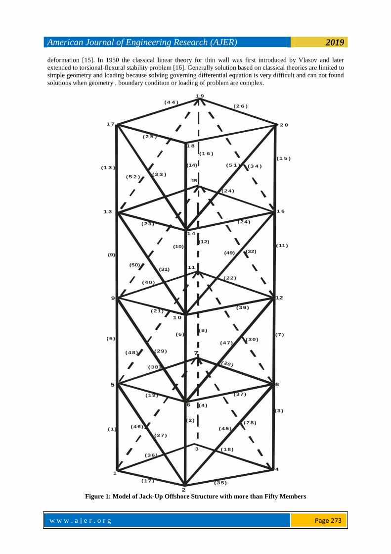
Figure 1: Model of Jack-Up Offshore Structure with more than Fifty Members
American Journal of Engineering Research (AJER) 2019
w w w . a j e r . o r g
w w w . a j e r . o r g
Page 274
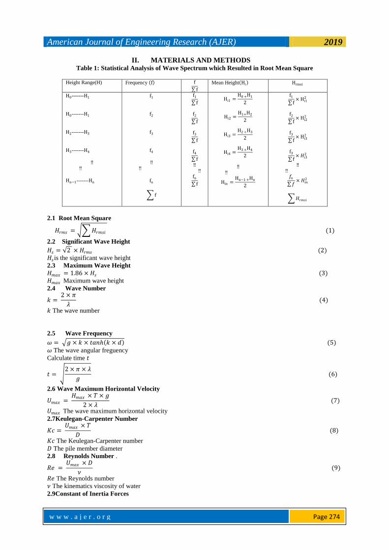
II. MATERIALS AND METHODS Table 1: Statistical Analysis of Wave Spectrum which Resulted in Root Mean Square
Height Range(H) Frequency f f
f
Mean Height Hi Hrmsi
H0-------H1
H0-------H1
H2-------H3
H3-------H4
‼ ‼
Hn−1-------Hn
f1
f2
f3
f4
‼ ‼
fn
f
f1
f
f2
f
f3
f
f4
f
‼ ‼
fn
f
Hi1 =H0 +H1
2
Hi2 =H1+H2
2
Hi3 =H2 +H3
2
Hi4 =H3 +H4
2
‼ ‼
Hin =Hn−1 +Hn
2
f1
f× Hi1
2
f2
f× Hi2
2
f3
f× Hi3
2
f3
f× 𝐻𝑖3
2
‼ ‼
𝑓𝑛 𝑓
× 𝐻𝑖𝑛2
𝐻𝑟𝑚𝑠𝑖
2.1 Root Mean Square
𝐻𝑟𝑚𝑠 = 𝐻𝑟𝑚𝑠𝑖 (1)
2.2 Significant Wave Height
𝐻𝑠 = 2 × 𝐻𝑟𝑚𝑠 (2)
𝐻𝑠 is the significant wave height
2.3 Maximum Wave Height
𝐻𝑚𝑎𝑥 = 1.86 × 𝐻𝑠 (3)
𝐻𝑚𝑎𝑥 Maximum wave height
2.4 Wave Number
𝑘 = 2 × 𝜋
𝜆 (4)
𝑘 The wave number
2.5 Wave Frequency
𝜔 = 𝑔 × 𝑘 × 𝑡𝑎𝑛 𝑘 × 𝑑 (5)
𝜔 The wave angular freguency
Calculate time 𝑡
𝑡 = 2 × 𝜋 × 𝜆
𝑔 (6)
2.6 Wave Maximum Horizontal Velocity
𝑈𝑚𝑎𝑥 = 𝐻𝑚𝑎𝑥 × 𝑇 × 𝑔
2 × 𝜆 (7)
𝑈𝑚𝑎𝑥 The wave maximum horizontal velocity
2.7Keulegan-Carpenter Number
𝐾𝑐 = 𝑈𝑚𝑎𝑥 × 𝑇
𝐷 (8)
𝐾𝑐 The Keulegan-Carpenter number
𝐷 The pile member diameter
2.8 Reynolds Number .
𝑅𝑒 = 𝑈𝑚𝑎𝑥 × 𝐷
𝜈 (9)
𝑅𝑒 The Reynolds number
𝜈 The kinematics viscosity of water
2.9Constant of Inertia Forces
American Journal of Engineering Research (AJER) 2019
w w w . a j e r . o r g
w w w . a j e r . o r g
Page 275
𝐴1
= 𝜋 × 𝐷
4 × 𝐻𝑚𝑎𝑥 (10)
𝐴1 The constant of inertia force
2.10 Constant of Drag Forces
𝐴2
= 2 × 𝑘 × 𝑑 + 𝑠𝑖𝑛 2 × 𝑘 × 𝑑
16 × 𝑠𝑖𝑛 𝑘 × 𝑑 2 (11)
𝐴2 The constant of drag force
2.11 Constant of Inertia Moment about the Seabed
𝐴3
= 𝜋 × 𝐷 × 1 + 𝑘 × 𝑑 × 𝑠𝑖𝑛 𝑘 × 𝑑 − 𝑐𝑜𝑠 𝑘 × 𝑑
4 × 𝐻𝑚𝑎𝑥 × 𝑠𝑖𝑛 𝑘 × 𝑑 (12)
𝐴3 The constant of inertia moment about the seabed
2.12 Constant of Drag Moment about the Seabed
𝐴4
= 2 × 𝑘2 × 𝑑2 + 2 × 𝑘 × 𝑑 × 𝑠𝑖𝑛 2 × 𝑘 × 𝑑 + 1 − 𝑐𝑜𝑠 2 × 𝑘 × 𝑑
64 × 𝑠𝑖𝑛 𝑘 × 𝑑 2 (13)
𝐴4 The constant of drag moment about the seabed
2.13 Inertia Wave Force
𝐹𝑚 =𝐷 × 𝜋 × 𝜌 × 𝐻𝑚𝑎𝑥
2 × 𝜆
𝑇2
× 𝐴1 × 𝐶𝑚 × 𝑠𝑖𝑛 𝜃 (14)
𝐹𝑚 The inertia wave force
𝜌 The sea water density
𝜃The wave phase angle in degrees
2.14 Drag Wave Force
𝐹𝑑 =𝐷 × 𝜋 × 𝜌 × 𝐻𝑚𝑎𝑥
2 × 𝜆
𝑇2
× 𝐴2 × 𝐶𝑑 × 𝑐𝑜𝑠 𝜃 × 𝑐𝑜𝑠 𝜃 (15)
𝐹𝑑 The drag wave force
2.15 Total Wave Force
F𝑇 = 𝐹𝑚 + 𝐹𝑑 = 𝐷 × 𝜋 × 𝜌 × 𝐻𝑚𝑎𝑥
2 × 𝜆
𝑇2
× 𝐴1 × 𝐶𝑚 × 𝑠𝑖𝑛 𝜃 + 𝐴2 × 𝐶𝑑 × 𝑐𝑜𝑠 𝜃 × 𝑐𝑜𝑠 𝜃 (16)
𝐹𝑇 The total wave force
2.16 Total Moment about the Seabed
𝑀 =𝐷 × 𝜋 × 𝜌 × 𝐻𝑚𝑎𝑥
2 × 𝜆2
𝑇2
× 𝐴3 × 𝐶𝑚 × 𝑠𝑖𝑛 𝜃 + 𝐴4 × 𝐶𝑑 × 𝑐𝑜𝑠 𝜃 × 𝑐𝑜𝑠 𝜃 (17)
2.17 Pile Members Forces
𝜃 = 𝑘 × 𝑥 − 𝑤 × 𝑡 (18)
𝑥 The minimum and maximum value x- direction length
The instantaneous wave height is the additional height
𝑧
= 𝐻𝑚𝑎𝑥
2× 𝑐𝑜𝑠 𝜃 (19)
𝑧 The instantaneous wave height
Constant of inertia pile force
𝐴11
= 𝑠𝑖𝑛 𝑘 × 𝑑 + 𝑧
2 × 𝑘 × 𝑠𝑖𝑛 𝑘 × 𝑑 (20)
𝐴11 The constant of inertia pile force
Constant of drag pile force
𝐴22 = 2 × 𝑘 × 𝑑 + 𝑧 + 𝑠𝑖𝑛 2 × 𝑑 × 𝑑 + 𝑧
32 × 𝑠𝑖𝑛 𝑘 × 𝑑 2 (21)
𝐴22 The constant of drag pile force
American Journal of Engineering Research (AJER) 2019
w w w . a j e r . o r g
w w w . a j e r . o r g
Page 276
Inertia pile member force
𝐹𝑚𝑝 = 𝐶𝑚 × 𝜌 ×𝜋 × 𝐷0
2
4× 𝐻𝑚𝑎𝑥 × 𝜔2 × 𝐴11 × 𝑠𝑖𝑛 𝜃 (22)
𝐹𝑚𝑝 The Inertia pile member force
Drag pile member force
𝐹𝑑𝑝 = 𝐶𝑑 × 𝜌 × 𝐷0 × 𝜔2 × 𝐻𝑚𝑎𝑥
2
𝑘𝐴22 × 𝑐𝑜𝑠 𝜃 × 𝑐𝑜𝑠 𝜃 (23)
𝐹𝑑𝑝 The Drag pile member force
Total pile member force
𝐹𝑇𝑝 = 𝐹𝑚𝑝 + 𝐹𝑑p (24)
𝐹𝑇𝑝 The Total pile member force
So at each of depth and x value specify on the input, the total pile force on the member would be calculated.
2.18 Horizontal y Bracing Members Forces Calculate velocity constant
𝐶 = 𝐶𝑑 × 𝜌 ×𝐷0
2 (25)
𝐶 The pile velocity constant
Calculate acceleration constant
𝐾𝑎 = 𝐶𝑚 × 𝜌 ×𝜋 × 𝐷0
4 (26)
𝐾𝑎 The pile acceleration constant
For 𝑥 = 0 𝑎𝑛𝑑 𝑥 = 𝑋𝑚𝑎𝑥
If 𝑑𝑖 < 𝑑
Phase angle of water wave on horizontal member
𝜃𝐻 = 𝑘 × 𝑥 − 𝑤 × 𝑡 (27)
𝜃𝐻 The Phase angle of water wave on horizontal member
Instantaneous wave height on horizontal members
𝑧𝐻 = 𝐻𝑚𝑎𝑥
2× 𝑐𝑜𝑠 𝜃𝐻 (28)
𝑧𝐻 The Instantaneous wave height on horizontal members
Velocity in x-direction
𝑉𝑥 = 𝜋 × 𝐻𝑚𝑎𝑥
𝑇×𝑐𝑜𝑠 𝑘 × 𝑑𝑖 + 𝑧𝐻
𝑠𝑖𝑛 𝑘 × 𝑑𝑖 × 𝑐𝑜𝑠 𝜃𝐻 (29)
𝑉𝑥 The velocity in x-direction
𝑑𝑖 The sea water depth based on section under consideration
Velocity in z-direction
𝑉𝑧 = 𝜋 × 𝐻𝑚𝑎𝑥
𝑇×𝑠𝑖𝑛 𝑘 × 𝑑𝑖 + 𝑧𝐻
𝑠𝑖𝑛 𝑘 × 𝑑𝑖 × 𝑠𝑖𝑛 𝜃𝐻 (30)
𝑉𝑧 The velocity in z-direction
Acceleration in x-direction
𝑎𝑥 = 2 × 𝜋2 × 𝐻𝑚𝑎𝑥
𝑇2×𝑐𝑜𝑠 𝑘 × 𝑑𝑖 + 𝑧𝐻
𝑠𝑖𝑛 𝑘 × 𝑑𝑖 × 𝑠𝑖𝑛 𝜃𝐻 (31)
𝑎𝑥 The acceleration in x-direction
Now, let solve for normal velocity in respect to each axis using below matrix equation
𝑉𝑛𝑥𝑉𝑛𝑦𝑉𝑛𝑧
=
1 − 𝐶𝑥2 −𝐶𝑥 × 𝐶𝑦 −𝐶𝑥 × 𝐶𝑧
−𝐶𝑥 × 𝐶𝑦 1 − 𝐶𝑦2 −𝐶𝑦 × 𝐶𝑧
−𝐶𝑥 × 𝐶𝑧 −𝐶𝑦 × 𝐶𝑧 1 − 𝐶𝑧2
×
𝑉𝑥𝑉𝑦𝑉𝑧
[17] (32)
Co-ordinate in x-direction 𝐶𝑥 = 0
Co-ordinate in y-direction 𝐶𝑦 = 1
Co-ordinate in z-direction 𝐶𝑧 = 0
𝑉𝑛𝑥 The normal velocity in x-direction

American Journal of Engineering Research (AJER) 2019
w w w . a j e r . o r g
w w w . a j e r . o r g
Page 277
𝑉𝑛𝑦 The normal velocity in y-direction
𝑉𝑛𝑧 The normal velocity in z-direction
From equation 3.35 values of 𝑉𝑛𝑥 ,𝑉𝑛𝑦 , 𝑎𝑛𝑑 𝑉𝑛𝑧 are gotten
Velocity magnitude
𝑉𝑛
= 𝑉𝑥2 + 𝑉𝑧
2 (33)
𝑉𝑛 The velocity magnitude
Now, let solve for normal acceleration in respect to each axis using below matrix equation, but since there is no
velocity on the y-axis there is corresponding no acceleration on the y-axis.
So, 𝑎𝑦 = 0
𝑎𝑛𝑥𝑎𝑛𝑦𝑎𝑛𝑧
=
1 − 𝐶𝑥2 −𝐶𝑥 × 𝐶𝑦 −𝐶𝑥 × 𝐶𝑧
−𝐶𝑥 × 𝐶𝑦 1 − 𝐶𝑦2 −𝐶𝑦 × 𝐶𝑧
−𝐶x × 𝐶𝑧 −𝐶𝑦 × 𝐶𝑧 1 − 𝐶𝑧2
×
𝑎𝑥𝑎𝑦𝑎𝑧 (34)
𝑎𝑛𝑥 The normal acceleration in x-direction
𝑎𝑛𝑦 The normal acceleration in y-direction
𝑎𝑛𝑧 The normal acceleration in z-direction
From above equation values of 𝑎𝑛𝑥 , 𝑎𝑛𝑦 , 𝑎𝑛𝑑 𝑎𝑛𝑧 are gotten
Total force per unit length on horizontal member bracing below waterline section
𝐹𝑖 = 𝐶 × 𝑉𝑛 × 𝑉𝑛 + 𝐾𝑎 × 𝑎𝑥 𝑁
𝑚 (35)
𝐹𝑖Total force per unit length on horizontal member bracing below waterline section
Total force on horizontal member bracing below waterline section
𝐹𝐻 = 𝐹𝑖 × 𝑌𝑚𝑎𝑥 𝑁 (36)
𝐹𝐻Total force on horizontal member bracing below waterline section
2.19 Displacement at each nodal point on the Jack-up
𝐹𝑥𝑛𝐹𝑦𝑛𝐹𝑧𝑛𝐹𝑥𝑛𝐹𝑦𝑛𝐹𝑧𝑛
=𝐸 × 𝐴
𝐿×
𝐶𝑥
2
𝐶𝑥 × 𝐶𝑦𝐶𝑥 × 𝐶𝑧−𝐶𝑥
2
−𝐶𝑥 × 𝐶𝑦−𝐶𝑥 × 𝐶𝑧
𝐶𝑥 × 𝐶𝑦
𝐶𝑦2
𝐶𝑦 × 𝐶𝑧−𝐶𝑥 × 𝐶𝑦
−𝐶𝑦2
−𝐶𝑦 × 𝐶𝑧
𝐶𝑥 × 𝐶𝑧𝐶𝑦 × 𝐶𝑧
𝐶𝑧2
−𝐶𝑥 × 𝐶𝑧−𝐶𝑦 × 𝐶𝑧
−𝐶𝑧2
−𝐶𝑥2
−𝐶𝑥 × 𝐶𝑦−𝐶𝑥 × 𝐶𝑧
𝐶𝑥2
𝐶𝑥 × 𝐶𝑦𝐶𝑥 × 𝐶𝑧
−𝐶x × Cy
−Cy2
−Cy × Cz
Cx × Cy
Cy2
Cy × Cz
−Cx × Cz
−Cy × Cz
−Cz2
Cx × Cz
Cy × Cz
Cz2
×
xn yn zn
xn yn zn
(37)
2.20Stress on each Member on the Jack-up Offshore Structure
The stress on each member can be calculated using the general formula for stress calculation
σm =E
L× Cx Cy Cz −Cx −Cy −Cz
×
x ny nz nx ny nz n
(38)
σm Stress of each member
The solution should use the scalar multiplication approach to resolve as shown below for each member stress
σm =E
L× Cx × x n + Cy × y n + Cz × z n + −Cx × x n + −Cy × y n + Cz × z n 39
American Journal of Engineering Research (AJER) 2019
w w w . a j e r . o r g
w w w . a j e r . o r g
Page 278
III. RESULT AND DISCUSSIONS
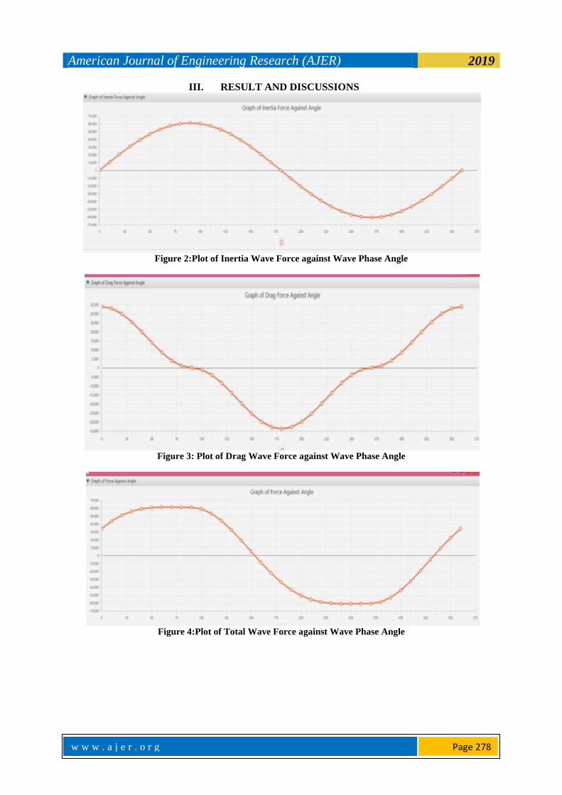
Figure 2:Plot of Inertia Wave Force against Wave Phase Angle
Figure 3: Plot of Drag Wave Force against Wave Phase Angle
Figure 4:Plot of Total Wave Force against Wave Phase Angle
American Journal of Engineering Research (AJER) 2019
w w w . a j e r . o r g
w w w . a j e r . o r g
Page 279
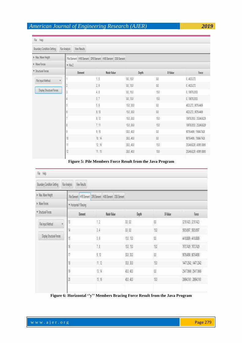
Figure 5: Pile Members Force Result from the Java Program
Figure 6: Horizontal ‘’y’’ Members Bracing Force Result from the Java Program

American Journal of Engineering Research (AJER) 2019
w w w . a j e r . o r g
w w w . a j e r . o r g
Page 280
Figure 7: Pile Members Stress and Displacement from the Java Program
Figure 8: Horizontal ‘’y’’ Bracing Members Stress and Displacement from the Java Program
Figure 2 is graphs of inertia wave force against wave phase angle, while Figure 6 is the java program
plot of the inertia wave force against wave phase angle, the graph start from the origin that is from zero to the

American Journal of Engineering Research (AJER) 2019
w w w . a j e r . o r g
w w w . a j e r . o r g
Page 281
maximum positive value of the inertia wave force at 90°, then move to zero again at 180° before it fall to
maximum negative value of the inertia wave force at 270° and finally back to zero at 360°, this is line because
the wave profile use for the inertia wave force contain sin θ which when plot move from zero to positive
maximum then to zero before it move to negative maximum then back to zero. Figure 3 is the java program plot
of the drag wave force against wave phase angle, it was seen that the graph start from the maximum positive
value of the drag wave force at 0°, then move to zero at 90° before it fall to maximum negative value of the drag
wave force at 180°, the move to zero at 270°, before it finally rise to maximum positive value of the drag wave
force at 360°,this is line because the wave profile use for the drag wave force contain cos θ which when plot
start from positive maximum to zero then it move to negative maximum then back to zero before it final rise to
the positive maximum again. Figure 4 is the java program plot of the total wave force against wave phase angle,
it was seen that the graph start from the origin with the value of the total wave force equal that of the drag wave
force at 0°to the maximum positive value of the total wave force at 90°, then move to zero at 180° before it fall
to maximum negative value of the total wave force at 270° and finally back to the positive value equal that of
drag wave force at 360°, this is in line because the wave profile use for the total wave force contain sin θand
cos θwhich when plot move from positive value to positive maximum value then to zero before it move to
negative maximum value then back to positive value.
In other to get each member force, stress and the displacement at each nodal point of the structure an
excel file input is created for pile members and other classes with the first column showing each member length
with the exception of the diagonal front bracing members and the diagonal side bracing members that the length
cannot be known except during calculation and the value of the length is replace by zero in both case while the
second column show each member outer diameter follow by the third column which show each member inner
diameter, then the fourth column which show each member angle with respect to x-axis co-ordinate while the
fifth column show each member angle with respect to y-axis co-ordinate then follow by the sixth column which
show each member angle in respect to z-axis co-ordinate also the seventh column show the first nodal point
value number as name on the structure while the eight column show the second nodal point value number as
name on the structure then the ninth column show the first water depth relative to the first node point of each
members while the tenth column show the second water depth relative to the second node point of each
members, then the eleventh column show the first value of x magnitude in relative to the first node point of each
members while the twelfth column show the second value of x magnitude in relative to the second node point of
each members.
By successful importing all the excel files created above, then each of members force is calculated by
the java program and the result shown is classes, Figure 5 show pile members force from the java program with
the force result on the fifth column, Figure 6 show horizontal y bracing members force from the java program
with the force result on the fifth column. The stress on each member and the displacement is calculated as show
in Figure 7 and Figure 8 from the java program, the displacement is based on the nodal value of each member
and the degree of freedom that is each member has six displacement since it has two node value and at each of
the node value has three degree of freedom, the degree of freedom simple imply direction which is x, y, and z in
this case.
IV. CONCLUSIONS From this research work I can conclude that the wave force result curves on the entire structure that is
figure1, figure 2 and figure 3 produced by the software are in line with what is obtainable in practice for a
regular wave, also since the force on each member from the software (java program) has the same results as
Deo, M.C. text when the same structure was considered, it can be said that the software (java program)
developed are in agreement with world standard practice when wave force on jack up members is been
considered and regular wave is been adopted, lastly since all the member stress gotten from the software (java
program) is far less than that of the global known stress limit for an iron material which is 90Mpa, it can be said
that even with factor of safety the software (java program) developed is within agreement for practical purpose,
while discussing the reason for java preferable over other programming language, mathematical model for jack
up structure were given and the software was developed and ran to give impressive results.
ACKNOWLEDGEMENT The Author would want to appreciate the assistance of the staff of the software laboratory of the Marine
Engineering Department of Rivers State University.
American Journal of Engineering Research (AJER) 2019
w w w . a j e r . o r g
w w w . a j e r . o r g
Page 282
REFERENCES [1]. Veldman, .H & Lager, G. (1997). Offshore foundation for offshore studies Deift, Netherland. [2]. Stiff, J. J., Sharples, B.P.M and Bowie, R.D. (1997). ‘’Jack-up classification past, present and future’’, proc6thinternational
conference on jack-up platform design, construction and operation, City university, London.
[3]. Bennett, W.T. &Sharples, B.P.M. (1987). Jack-up legs to stand on mobileOffshore structures, Elsevier, London, page 1-32 [4]. Baerheim, M., Manschot, D. &Nortvedt, T. (1997). Proc of 6th international Conference jack-up platform design, construction and
operation, City University London.
[5]. Morrison, J.R., O’Brien, M.P., Johnson, J.W. &Schaaf, S.A. (1950). Force exerted by surface waves on piles,petroleum transactions, AIME Volume 189, Page 149-157.
[6]. Verley, R.L.P. (1982). Simple model of vortex induced forces in waves and Oscillating currents.
[7]. Sarpkaya, T. &Issacson, M. (1981). Mechanics of wave induced forces on offshoreStructure, Van Nostrand Reinhold. [8]. Almar-Naess, A. (1985). Fatigue handbook: offshore steel structures, Trondheim
[9]. Dover, W.D. &MadhavaRao, A.G. (1996). Fatigue in offshore structures Volume 1.Balkema, Rotterdam/Brookfield.
[10]. Etube, L.S., Brennan, F.F. & Dover, W.D. (1999). Modeling of jack-upResponse for fatigue under simulated service conditions. Marine Structures, Page 327-348.
[11]. Ramachandra, M. D.S., Madhava, R. A.G. &Santhakumar, A.R. (1994). Corrosion fatigue of stiffened offshore steel tubular joints
journal of StructuralEngineering, page 1991-2080. [12]. Gandhi, .P, Raghava&Ramachandra Murthy, D.S. (2000). Fatigue behaviour of internallyring-stiffened welded steel tubular joints,
Journal of Structural Engineering, page 809-815.
[13]. Vugts, J.H. (2005). ‘’Damage assessments and the influence of wave directionality’’, Applied ocean research, page 173-185. [14]. Shunfeng, G Yong He &Weiliang Jin, (2007). Fatigue life reliability Analysis of dynamic response spectrum for offshore platform,
Structures Journal of Zhejiang University.page 12-17. [15]. Ditlevsen, O. (1979) Narrow reliability bounds for structural system, journals of Structural mechanic page 42-61.
[16]. Zienkiewicz, O.C. & Taylor, R.L. (2000). Finite element method solid mechanics, Vol. 2 Butter worth-Heinemann, oxford.
[17]. Deo, M.C. (2013), Wave and Structure Civil Engineering Indian Institute ofTechnology Bombay Powai Mumbai.
Olusegun Samuel Dare" Wave Forces, Displacements and Stresses on Offshore Structures (Using
Africa Waters)" American Journal of Engineering Research (AJER), vol.8, no.02, 2019, pp.271-
282