wave monitors - north inventnorthinvent.com/content/uploads/2014/09/wave-um-rev1.1-10-2014.pdf ·...
TRANSCRIPT

Specifications subject to changes without prior notice.The contents of
this page are property of North Invent Norway AS. All rights herein are
reserved to North lnvent Norway AS. This document cannot be
reproduced without the written permission of the company.
Wave Monitors
NORTH INVENT Sørhauggata 128, NO-5527 Haugesund, Norway Phone: + 47 48 84 02 00 [email protected] www.northinvent.com
Oktober 2014
USER'S MANUAL
Wave Monitors
Specifications subject to changes without prior notice.The contents of
this page are property of North Invent Norway AS. All rights herein are
reserved to North lnvent Norway AS. This document cannot be
reproduced without the written permission of the company.
NORTH INVENT Sørhauggata 128, NO-5527 Haugesund, Norway Phone: + 47 48 84 02 00 [email protected] www.northinvent.com
2
Table of Contents
1. Foreword ...................................................................................................................................................................... 3
1.0 Terms and abbreviations.....................................................................................................................3
1.1 Monitor description ........................................................................................................................... 3
1.2 Product identification………………………………………………….………………………..…………..5
1.3 Main schematic overview .................................................................................................................. 6
1.4 Packaging and delivery ...................................................................................................................... 7
1.5 Mechanical Dimensions .................................................................................................................... 7
1.6 Electrical installation ........................................................................................................................ 8
2. Operating Instructions ........................................................................................................................................... 10
2.1 Controls and indicators .................................................................................................................... 10
2.2 Start-up .......................................................................................................................................... 10
2.3 Source Input Messages .................................................................................................................... 11
2.4 On Screen Display (OSD) ................................................................................................................ 11
2.4.1 OSD division into folders, menus, sub-menus ................................................................................ 12
2.4.2 OSD items ......................................................................................................................................... 12
2.4.3 OSD items stages .............................................................................................................................. 13
2.4.4 Entering and adjusting the OSD ........................................................................................................ 13
2.4.5 OSD content ...................................................................................................................................... 14
Tools………………………………………………………………………………………………………......15
Functions ........................................................................................................................................................ 17
Picture ............................................................................................................................................................. 19
RGB mode wizard .......................................................................................................................................... 20
Info ................................................................................................................................................................. 21
2.5 Mode Table .................................................................................................................................... 22
2.6 Remote control ............................................................................................................................... 23
3. Technical specifications ........................................................................................................................................ 28
3.1 Summary ........................................................................................................................................ 28
3.2 Firmware Revision table .................................................................................................................. 29
3.3 Troubleshooting .............................................................................................................................. 29
3.4 Cleaning ......................................................................................................................................... 30
3.5 Update ........................................................................................................................................... 30
4. Maintenance and service ....................................................................................................................................... 30

Wave Monitors
Specifications subject to changes without prior notice.The contents of
this page are property of North Invent Norway AS. All rights herein are
reserved to North lnvent Norway AS. This document cannot be
reproduced without the written permission of the company.
NORTH INVENT Sørhauggata 128, NO-5527 Haugesund, Norway Phone: + 47 48 84 02 00 [email protected] www.northinvent.com
3
1. Foreword Thanks for purchasing a North Invent Wave Monitor. Our series of rugged TFT LCD Display Monitors are conceived and built with the greatest care and state of the art electronic and software features. North Invent focuses its full expertise in offering dedicated display solutions, matching with your highest requirements and use. Before starting operating the Monitor, we would like to suggest that you carefully read through the present document, as our aim with this User’s Manuel is to give you the best experience in using our Monitors. May you have any suggestions for improvements, or any feedbacks about this manual, the Monitor and/or its features, feel free to contact us. We will be pleased to oblige.
This User’s Manual is for use only with our Wave Monitors. To assess which series of Monitor you are in possession of, please check the Serial Number plate at the back of the screen. The mention shall bear WAxxx (see below). May you have a different series of Monitor, please contact us, so to have the proper manual sent to your attention.
1.0 Terms and abbreviations
DVI Digital Visual Interface DVI-A - Analog DVI-I -Integrated HMI Human- Machine Interface LCD Liquid Crystal Display LED Light-Emitting Diode OSD On-Screen Display RGB Red-Green-Blue TFT Thin Film Transistor VGA Video Graphics Array
1.1 Monitor description
The Wave monitors are a series of rugged TFT LCD Display Monitors available in 19’’, 21,5’’, 24" and 27" display sizes. All of our Monitors can be console mounted or equipped with stand and sunshade.
Each Wave Monitor is designated as below:
WA 190 01 MON 01 xxxx
WA 215 01 MON 01 xxxx
WA 240 01 MON 01 xxxx
WA 270 01 MON 01 xxxx
Wave Monitors
Specifications subject to changes without prior notice.The contents of
this page are property of North Invent Norway AS. All rights herein are
reserved to North lnvent Norway AS. This document cannot be
reproduced without the written permission of the company.
NORTH INVENT Sørhauggata 128, NO-5527 Haugesund, Norway Phone: + 47 48 84 02 00 [email protected] www.northinvent.com
4
Where “WA” stands for Wave, “190/215/240/270” for the display’s Size, “01” in third coulomb for the hardware Revision, “MON“ for Monitor, “01” in fifth coulomb for standard version of Wave and “xxxx” for identification of minor variants (flash logo, OEM labels etc.).
Each Monitor is constituted by the following set of components:
- Front glass with the User Interface Panel - Display Frame and all necessary electronic components - Rear cover and Terminal plate - 1 x Power AC Cable / 1 x DC plug / 1 x VGA Cable
(optional)
- DVI cable - RS232 cable - Sunshade
Each Monitor presents the following materials and features:
- The Front, Display Frame, Cover and Sunshade are made of Marine Grade Aluminium allowing to reduce weight while eliminating corrosion problems.
- The electronic set of components includes a specifically designed Power Supply, a high quality Display Controller, a Backlight LED driver and a custom-made Interface Board.
- All our Monitors use identical Power Supply and User Panel. The Power Supply can be supplied with 90-264 VAC and/or 18-36 VDC, and even be used as a part of an UPS. As an extra feature you have a 12 VDC 30W output.
- All our Monitors come with VGA, DVI, S-Video and Composite video inputs, and a RS232 input for remote control purposes.
- Pixel pitch on all displays varies from 0,248 to 0,311 mm both in x and y direction depending on the display size (see data sheet). Pixel pitch equals 1,07 m viewing distance with a viewing angle of 1 minute of arc as required in IEC 62.288 section 7.5.1 for the 27" monitor, 1,02 m for the 19" monitor, 0,96 m for the 24" monitor and 0,86 m for the 21" monitor. Nominal viewing distance in a normal environment is 1,0 m.

Wave Monitors
Specifications subject to changes without prior notice.The contents of
this page are property of North Invent Norway AS. All rights herein are
reserved to North lnvent Norway AS. This document cannot be
reproduced without the written permission of the company.
NORTH INVENT Sørhauggata 128, NO-5527 Haugesund, Norway Phone: + 47 48 84 02 00 [email protected] www.northinvent.com
5
Each Monitor complies with the following international Standards and Requirements:
- All our Monitors has been tested by the Danish testing body “DELTA” (Danish Electronics, Light & Acoustics, DK-2970 Hørsholm) and found to comply with the requirements of the International Association of Classification Societies (IACS) as well as the selected requirements of IEC 60945, IEC 60533, IEC 60529 and MIL-STD-810F.
- The 19", 24" and 27" Wave monitors are also tested according to IEC 62288, IEC 62388 and IEC 61174 and thereby ECDIS approved
- All our Monitors are approved in compliance with the international standard IEC 60945 : 2002 (Clause 4.4 Equipment category b, protected from the weather (formerly class B)), Maritime navigation and radiocommunication equipment and systems - General requirements - Methods of testing and required test results.
- The compass safe distance indication is placed on the rear label (see figure 1.) and is valid for the Monitor
only.
1.2 Product identification
On the backside on top a label with productidentification is placed . Here monitor number and S/N are printet. See example on picture below.
Wave Monitors
Specifications subject to changes without prior notice.The contents of
this page are property of North Invent Norway AS. All rights herein are
reserved to North lnvent Norway AS. This document cannot be
reproduced without the written permission of the company.
NORTH INVENT Sørhauggata 128, NO-5527 Haugesund, Norway Phone: + 47 48 84 02 00 [email protected] www.northinvent.com
6
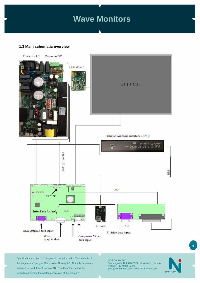
1.3 Main schematic overview
Wave Monitors
Specifications subject to changes without prior notice.The contents of
this page are property of North Invent Norway AS. All rights herein are
reserved to North lnvent Norway AS. This document cannot be
reproduced without the written permission of the company.
NORTH INVENT Sørhauggata 128, NO-5527 Haugesund, Norway Phone: + 47 48 84 02 00 [email protected] www.northinvent.com
7
1.4 Packaging and delivery
Please check the delivered goods immediately on receipt with respect to damages caused by transportation and inform the delivering freight carrier immediately, on site, about any visible transport damages. Additionally, inform us immediately in writing, at the latest within 5 work days, about any visible transport damages. At reception, the delivery includes the following items:
- Wave Monitor - Wave User’s Manual - VGA cable - AC power cable - DC power plug - DVI cable (optional) - RS232 cable (optional) - Sunshade (optional) - Sunshade mounting screws and screw covers (optional)
1.5 Mechanical Dimensions
For panel cut out drawings and mechanical dimensions of monitors see data sheets.

Wave Monitors
Specifications subject to changes without prior notice.The contents of
this page are property of North Invent Norway AS. All rights herein are
reserved to North lnvent Norway AS. This document cannot be
reproduced without the written permission of the company.
NORTH INVENT Sørhauggata 128, NO-5527 Haugesund, Norway Phone: + 47 48 84 02 00 [email protected] www.northinvent.com
8
1.6 Electrical installation
- All electrical connections are to be found on the lower back side of the Monitor. All necessary electrical indications are to be found on the Terminal Plate at the bottom of the Monitor’s backside.
Figure 1. Terminal Plate for a Wave Monitor.
Power supply - The Monitor can be supplied with 90-264 VAC and/or 18-36 VDC.
- The Monitor is connected to AC voltage by means of the standard AC power cable included in the delivery.
The AC current to the Monitor must be limited by a 3A fuse or similar. - The Monitor is connected to DC voltage by means of the DC power plug included in the delivery and wires
suitable for up to 8 A. The Monitor will not be damaged by reversed polarity, may it occur.
VGA cable (Analog RGB) - The VGA cable is included in the delivery.
- Remember to fasten the VGA cable’s fixing screws for adequate connection.
DVI cable (Digital RGB) - The DVI cable is not included in a standard delivery but is available as an option. - The DVI cable is to be connected to the DVI-I terminal. Be sure to use a high quality DVI cable with correct
termination of shield. - Remember to fasten the DVI cable’s fixing screws for adequate connection.
Video cables - Video signals can be obtained by connecting the Monitor to the S-VHS (S-Video) and CVBS (composite video)
terminals. The video cables must be of high quality in order to avoid signal’s interference.
RS232 cable - The Monitor is equipped with a standard 9-pin D-SUB female connector for RS232 remote control. - Further information about this interface and the remote control is to be found in the Remote Control section.
Wave Monitors
Specifications subject to changes without prior notice.The contents of
this page are property of North Invent Norway AS. All rights herein are
reserved to North lnvent Norway AS. This document cannot be
reproduced without the written permission of the company.
NORTH INVENT Sørhauggata 128, NO-5527 Haugesund, Norway Phone: + 47 48 84 02 00 [email protected] www.northinvent.com
9
Compass safe-distance - Every component of type approved equipment is tested in order to determine the minimum safe distances at
which it should be installed from both the steering and the standard magnetic compasses, so not to significantly affect the accuracy of these compasses. The safe compass distances are mentioned on every Monitor or in the accompanying handbook. A safe distance takes into account both the constant effect on a magnetic compass, of the presence of magnetic material but also any variable effect due, for instance, to electrical circuits or the opening/closing of drawers or panels. Thus, provided that a Monitor is not placed in a position nearer to the centre of the bowl of a magnetic compass than the recommended safe distance, the Monitor may be installed or removed without any need for adjustment of that compass.
- WA190-01.MON.01 0.95 m - WA215-01.MON.01 1,00 m - WA240-01.MON.01 1,00 m - WA270-01.MON.01 1,15 m - The safe distance is also indicated on the terminal plate of every Monitor as shown on Figure 1.

Wave Monitors
Specifications subject to changes without prior notice.The contents of
this page are property of North Invent Norway AS. All rights herein are
reserved to North lnvent Norway AS. This document cannot be
reproduced without the written permission of the company.
NORTH INVENT Sørhauggata 128, NO-5527 Haugesund, Norway Phone: + 47 48 84 02 00 [email protected] www.northinvent.com
10
2. Operating Instructions The following instructions assume that the Monitor has been correctly installed and that the commissioning work has been finalised.
2.1 Controls and indicators
- Controls and Indicators are placed on the User Panel in the lower right side of the Monitor. - Normal functioning of the Control knobs and Indicators are explained in the following table:
Control / Indicator Function
POWER Press once to switch the Monitor ON. Press for 5 sec to switch the Monitor OFF.
AC Indicates that the Monitor is supplied with 90-264 VAC.
DC Indicates that the Monitor is supplied with 18-36 VDC
LOCK Press once to activate the OSD in unlocked state. Press LOCK and MENU for 5 sec to unlock and activate the OSD in locked state.
MENU Press once to activate the OSD in unlocked state. Press once to deactivate the OSD again. Press once to change from sub to main menu.
SET Press to indicate/change the video input source (OSD not active). Press once to go to the selected sub menu (OSD active). Press once to set or unset the selected sub menu (OSD active).
+ Press and hold to increase the indicator brightness (OSD not active). Press once to select the next menu (OSD active). Press or hold to increase values (OSD active).
− Press or hold to decrease the indicator brightness (OSD not active). Press once to select the previous menu (OSD is active). Press or hold to decrease values (OSD active).
Figure 2. Front Panel with controls and indicators.
2.2 Start-up
- Ensure that power and a valid video signal are supplied to the Monitor. Standard video signals are listed in the
Mode Table section below.
Wave Monitors
Specifications subject to changes without prior notice.The contents of
this page are property of North Invent Norway AS. All rights herein are
reserved to North lnvent Norway AS. This document cannot be
reproduced without the written permission of the company.
NORTH INVENT Sørhauggata 128, NO-5527 Haugesund, Norway Phone: + 47 48 84 02 00 [email protected] www.northinvent.com
11
- Press the Power control once – the Power, LOCK and relevant AC/DC indicators will light up. The control and
indicator backlight can be adjusted using the +/− controls. When Locked (e.g. ECDIS mode) the indicator and the control panel backlight will follow dimming of the display backlight. In ECDIS mode the backlight, control and indicator are preset to Day, Dusk and Night (controlled via RS232).
- The Monitor will search for a video signal on the last selected input source. If the Monitor states “No Input
Signal – Going to Sleep”, the correct source can be selected using the OSD (see below). The default source is the standard VGA input.
- The screen brightness can now be adjusted using the +/− controls on the Front Panel and the picture
positioning and size can be adjusted using the OSD (see below).
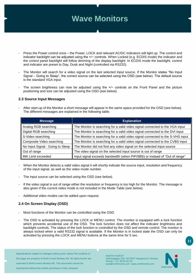
2.3 Source Input Messages
- After start-up of the Monitor a short message will appear in the same space provided for the OSD (see below).
The different messages are explained in the following table.
Message Explanation
Analog RGB searching The Monitor is searching for a valid video signal connected to the VGA input
Digital RGB searching The Monitor is searching for a valid video signal connected to the DVI input
S-Video searching The Monitor is searching for a valid video signal connected to the S-VHS input
Composite Video searching The Monitor is searching for a valid video signal connected to the CVBS input
No Input Signal - Going to Sleep The Monitor did not find any video signal on the selected input source
Out of range The video signal on the selected input source is out of range
BW Limit exceeded Input signal exceeds bandwidth (when PIP/SBS) or instead of “Out of range”
- When the Monitor detects a valid video signal it will shortly indicate the source input, resolution and frequency
of the input signal, as well as the video mode number. - The input source can be selected using the OSD (see below). - If the video signal is out of range either the resolution or frequency is too high for the Monitor. The message is
also given if the current video mode is not included in the Mode Table (see below). - Additional video modes can be added upon request.
2.4 On Screen Display (OSD)
- Most functions of the Monitor can be controlled using the OSD. - The OSD is activated by pressing the LOCK or MENU control. The monitor is equipped with a lock function
which prevents accidental use of the OSD. The lock function does not affect the indicator brightness and backlight controls. The status of the lock function is controlled by the OSD and remote control. The monitor is always locked when a valid RS232 signal is available. If the Monitor is in locked state the OSD can only be activated by pressing the LOCK and MENU buttons at the same time for 5 sec.
Wave Monitors
Specifications subject to changes without prior notice.The contents of
this page are property of North Invent Norway AS. All rights herein are
reserved to North lnvent Norway AS. This document cannot be
reproduced without the written permission of the company.
NORTH INVENT Sørhauggata 128, NO-5527 Haugesund, Norway Phone: + 47 48 84 02 00 [email protected] www.northinvent.com
12
- The screen backlight (brightness) can be adjusted using the +/− controls on the front panel but it can also be
adjusted using the OSD and remote control. Normal operation shall be backlight 100%. - The next and previous menu can be selected using + / − controls. - The sub menus are selected using the SET control and values can be increased/decreased using + / −
controls. The SET control is also used to set the value and leave the sub menu. - Press the MENU control once to return to the main menu and once again to leave the OSD. - The OSD will be deactivated the selected period after the last control has been pressed (OSD timeout).
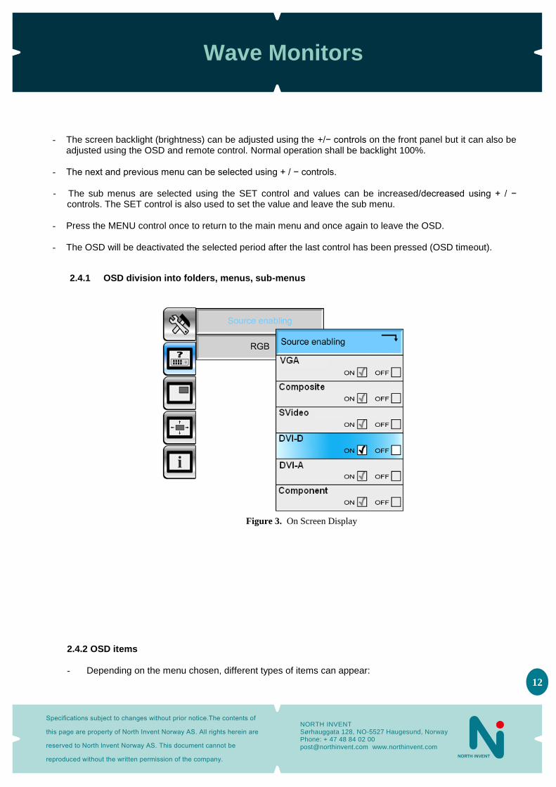
2.4.1 OSD division into folders, menus, sub-menus
Figure 3. On Screen Display
2.4.2 OSD items
- Depending on the menu chosen, different types of items can appear:
Wave Monitors
Specifications subject to changes without prior notice.The contents of
this page are property of North Invent Norway AS. All rights herein are
reserved to North lnvent Norway AS. This document cannot be
reproduced without the written permission of the company.
NORTH INVENT Sørhauggata 128, NO-5527 Haugesund, Norway Phone: + 47 48 84 02 00 [email protected] www.northinvent.com
13
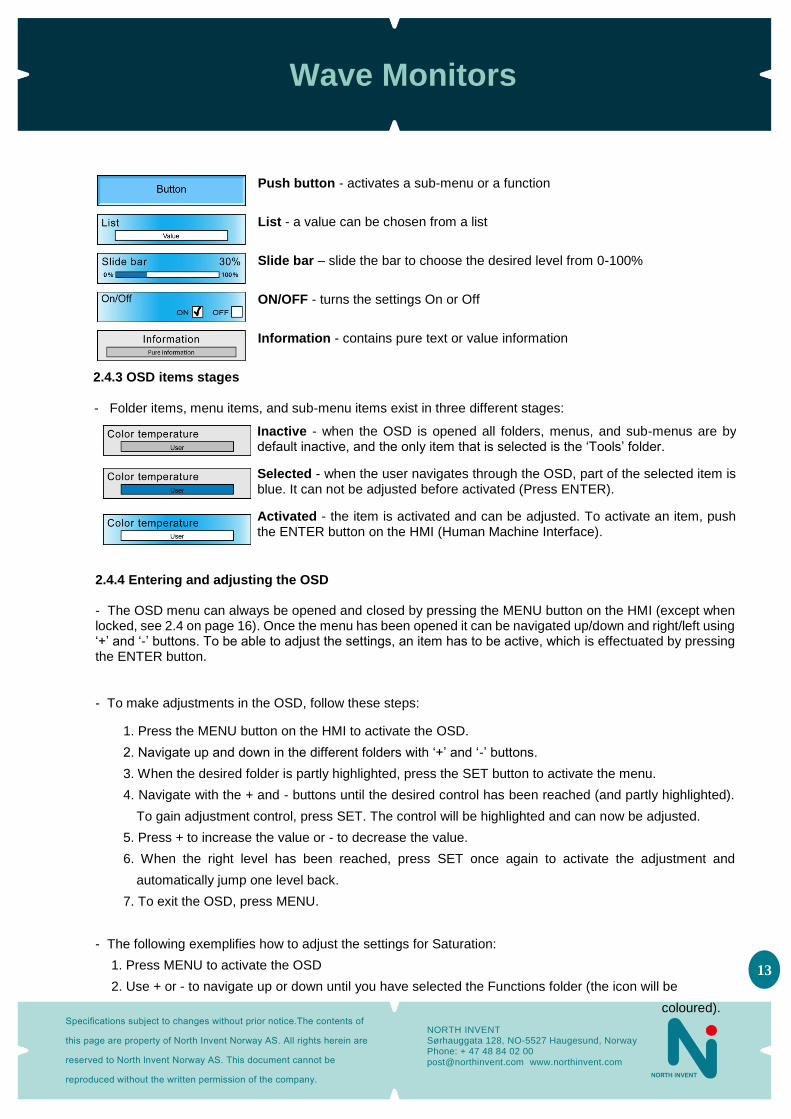
Push button - activates a sub-menu or a function
List - a value can be chosen from a list
Slide bar – slide the bar to choose the desired level from 0-100%
ON/OFF - turns the settings On or Off
Information - contains pure text or value information
2.4.3 OSD items stages
- Folder items, menu items, and sub-menu items exist in three different stages:
Inactive - when the OSD is opened all folders, menus, and sub-menus are by default inactive, and the only item that is selected is the ‘Tools’ folder.
Selected - when the user navigates through the OSD, part of the selected item is blue. It can not be adjusted before activated (Press ENTER).
Activated - the item is activated and can be adjusted. To activate an item, push the ENTER button on the HMI (Human Machine Interface).
2.4.4 Entering and adjusting the OSD
- The OSD menu can always be opened and closed by pressing the MENU button on the HMI (except when locked, see 2.4 on page 16). Once the menu has been opened it can be navigated up/down and right/left using ‘+’ and ‘-’ buttons. To be able to adjust the settings, an item has to be active, which is effectuated by pressing the ENTER button.
- To make adjustments in the OSD, follow these steps:
1. Press the MENU button on the HMI to activate the OSD.
2. Navigate up and down in the different folders with ‘+’ and ‘-’ buttons.
3. When the desired folder is partly highlighted, press the SET button to activate the menu.
4. Navigate with the + and - buttons until the desired control has been reached (and partly highlighted).
To gain adjustment control, press SET. The control will be highlighted and can now be adjusted.
5. Press + to increase the value or - to decrease the value.
6. When the right level has been reached, press SET once again to activate the adjustment and
automatically jump one level back.
7. To exit the OSD, press MENU.
- The following exemplifies how to adjust the settings for Saturation:
1. Press MENU to activate the OSD
2. Use + or - to navigate up or down until you have selected the Functions folder (the icon will be
coloured).

Wave Monitors
Specifications subject to changes without prior notice.The contents of
this page are property of North Invent Norway AS. All rights herein are
reserved to North lnvent Norway AS. This document cannot be
reproduced without the written permission of the company.
NORTH INVENT Sørhauggata 128, NO-5527 Haugesund, Norway Phone: + 47 48 84 02 00 [email protected] www.northinvent.com
14
3. Press SET to activate the folder (the folder will turn blue, and automatically the first menu item in the sub-
menu will be selected - in this case the ‘Source enabling’ button)
4. Use ‘+’ to navigate to DVI-A (or other Source input) and press ‘SET’ to activate
5. Navigate down with the + button until you have selected the menu item ‘Saturation’
6. Press SET to activate the menu item.
7. Use + or - to set the desired value for the saturation
8. Press SET to validate the change - the OSD automatically jumps one level back
2.4.5 OSD content
- The OSD is designed with 6 different folders: Tools, Functions, Source, Picture, RGB mode wizard, and Info, each of which has their own menu. Several of the menu items furthermore have sub-menus to be navigated through. In the following pages, the different settings will be described:
Wave Monitors
Specifications subject to changes without prior notice.The contents of
this page are property of North Invent Norway AS. All rights herein are
reserved to North lnvent Norway AS. This document cannot be
reproduced without the written permission of the company.
NORTH INVENT Sørhauggata 128, NO-5527 Haugesund, Norway Phone: + 47 48 84 02 00 [email protected] www.northinvent.com
15
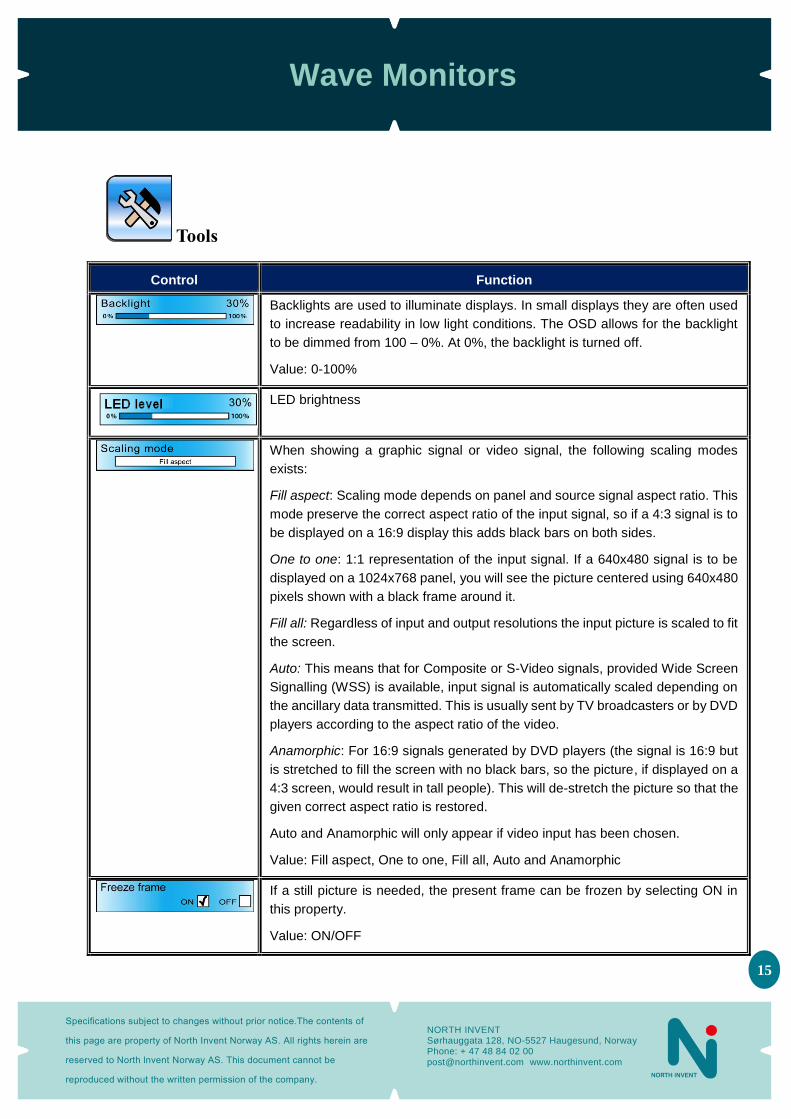
Tools
Control Function
Backlights are used to illuminate displays. In small displays they are often used
to increase readability in low light conditions. The OSD allows for the backlight
to be dimmed from 100 – 0%. At 0%, the backlight is turned off.
Value: 0-100%
LED brightness
When showing a graphic signal or video signal, the following scaling modes
exists:
Fill aspect: Scaling mode depends on panel and source signal aspect ratio. This
mode preserve the correct aspect ratio of the input signal, so if a 4:3 signal is to
be displayed on a 16:9 display this adds black bars on both sides.
One to one: 1:1 representation of the input signal. If a 640x480 signal is to be
displayed on a 1024x768 panel, you will see the picture centered using 640x480
pixels shown with a black frame around it.
Fill all: Regardless of input and output resolutions the input picture is scaled to fit
the screen.
Auto: This means that for Composite or S-Video signals, provided Wide Screen
Signalling (WSS) is available, input signal is automatically scaled depending on
the ancillary data transmitted. This is usually sent by TV broadcasters or by DVD
players according to the aspect ratio of the video.
Anamorphic: For 16:9 signals generated by DVD players (the signal is 16:9 but
is stretched to fill the screen with no black bars, so the picture, if displayed on a
4:3 screen, would result in tall people). This will de-stretch the picture so that the
given correct aspect ratio is restored.
Auto and Anamorphic will only appear if video input has been chosen.
Value: Fill aspect, One to one, Fill all, Auto and Anamorphic
If a still picture is needed, the present frame can be frozen by selecting ON in
this property.
Value: ON/OFF
Wave Monitors
Specifications subject to changes without prior notice.The contents of
this page are property of North Invent Norway AS. All rights herein are
reserved to North lnvent Norway AS. This document cannot be
reproduced without the written permission of the company.
NORTH INVENT Sørhauggata 128, NO-5527 Haugesund, Norway Phone: + 47 48 84 02 00 [email protected] www.northinvent.com
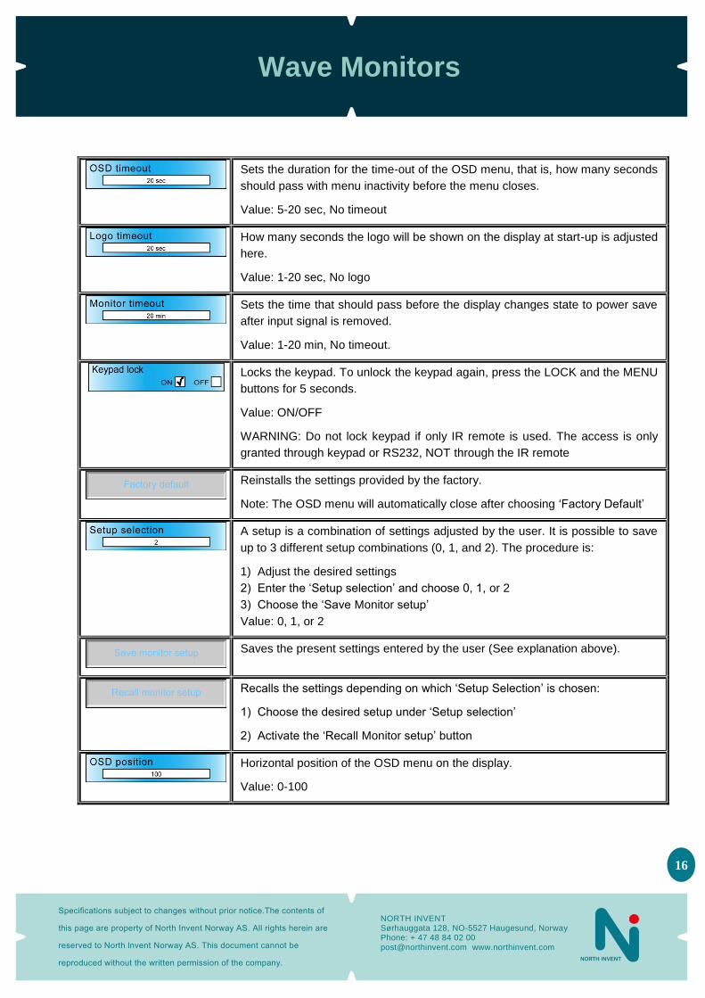
16
Sets the duration for the time-out of the OSD menu, that is, how many seconds
should pass with menu inactivity before the menu closes.
Value: 5-20 sec, No timeout
How many seconds the logo will be shown on the display at start-up is adjusted
here.
Value: 1-20 sec, No logo
Sets the time that should pass before the display changes state to power save
after input signal is removed.
Value: 1-20 min, No timeout.
Locks the keypad. To unlock the keypad again, press the LOCK and the MENU
buttons for 5 seconds.
Value: ON/OFF
WARNING: Do not lock keypad if only IR remote is used. The access is only
granted through keypad or RS232, NOT through the IR remote
Reinstalls the settings provided by the factory.
Note: The OSD menu will automatically close after choosing ‘Factory Default’
A setup is a combination of settings adjusted by the user. It is possible to save
up to 3 different setup combinations (0, 1, and 2). The procedure is:
1) Adjust the desired settings
2) Enter the ‘Setup selection’ and choose 0, 1, or 2
3) Choose the ‘Save Monitor setup’
Value: 0, 1, or 2
Saves the present settings entered by the user (See explanation above).
Recalls the settings depending on which ‘Setup Selection’ is chosen:
1) Choose the desired setup under ‘Setup selection’
2) Activate the ‘Recall Monitor setup’ button
Horizontal position of the OSD menu on the display.
Value: 0-100
Wave Monitors
Specifications subject to changes without prior notice.The contents of
this page are property of North Invent Norway AS. All rights herein are
reserved to North lnvent Norway AS. This document cannot be
reproduced without the written permission of the company.
NORTH INVENT Sørhauggata 128, NO-5527 Haugesund, Norway Phone: + 47 48 84 02 00 [email protected] www.northinvent.com
17
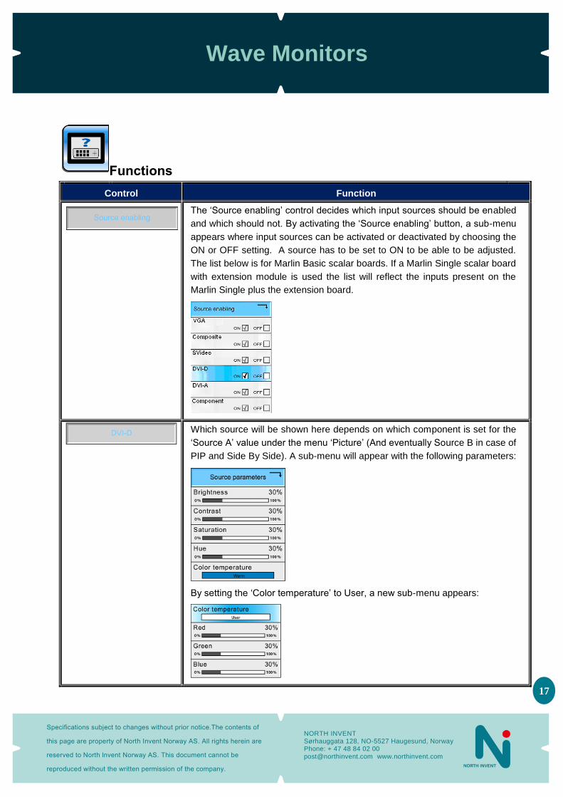
Functions
Control Function
The ‘Source enabling’ control decides which input sources should be enabled
and which should not. By activating the ‘Source enabling’ button, a sub-menu
appears where input sources can be activated or deactivated by choosing the
ON or OFF setting. A source has to be set to ON to be able to be adjusted.
The list below is for Marlin Basic scalar boards. If a Marlin Single scalar board
with extension module is used the list will reflect the inputs present on the
Marlin Single plus the extension board.
Which source will be shown here depends on which component is set for the
‘Source A’ value under the menu ‘Picture’ (And eventually Source B in case of
PIP and Side By Side). A sub-menu will appear with the following parameters:
By setting the ‘Color temperature’ to User, a new sub-menu appears:
Wave Monitors
Specifications subject to changes without prior notice.The contents of
this page are property of North Invent Norway AS. All rights herein are
reserved to North lnvent Norway AS. This document cannot be
reproduced without the written permission of the company.
NORTH INVENT Sørhauggata 128, NO-5527 Haugesund, Norway Phone: + 47 48 84 02 00 [email protected] www.northinvent.com
18
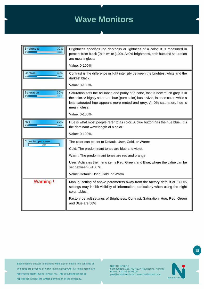
Brightness specifies the darkness or lightness of a color. It is measured in
percent from black (0) to white (100). At 0% brightness, both hue and saturation
are meaningless.
Value: 0-100%
Contrast is the difference in light intensity between the brightest white and the
darkest black.
Value: 0-100%
Saturation sets the brilliance and purity of a color, that is how much grey is in
the color. A highly saturated hue (pure color) has a vivid, intense color, while a
less saturated hue appears more muted and grey. At 0% saturation, hue is
meaningless.
Value: 0-100%
Hue is what most people refer to as color. A blue button has the hue blue. It is
the dominant wavelength of a color.
Value: 0-100%
The color can be set to Default, User, Cold, or Warm:
Cold: The predominant tones are blue and violet.
Warm: The predominant tones are red and orange.
User: Activates the menu items Red, Green, and Blue, where the value can be
set between 0-100 %.
Value: Default, User, Cold, or Warm
Warning ! Manual setting of above parameters away from the factory default or ECDIS
settings may inhibit visibility of information, particularly when using the night
color tables.
Factory default settings of Brightness, Contrast, Saturation, Hue, Red, Green
and Blue are 50%
Wave Monitors
Specifications subject to changes without prior notice.The contents of
this page are property of North Invent Norway AS. All rights herein are
reserved to North lnvent Norway AS. This document cannot be
reproduced without the written permission of the company.
NORTH INVENT Sørhauggata 128, NO-5527 Haugesund, Norway Phone: + 47 48 84 02 00 [email protected] www.northinvent.com
19
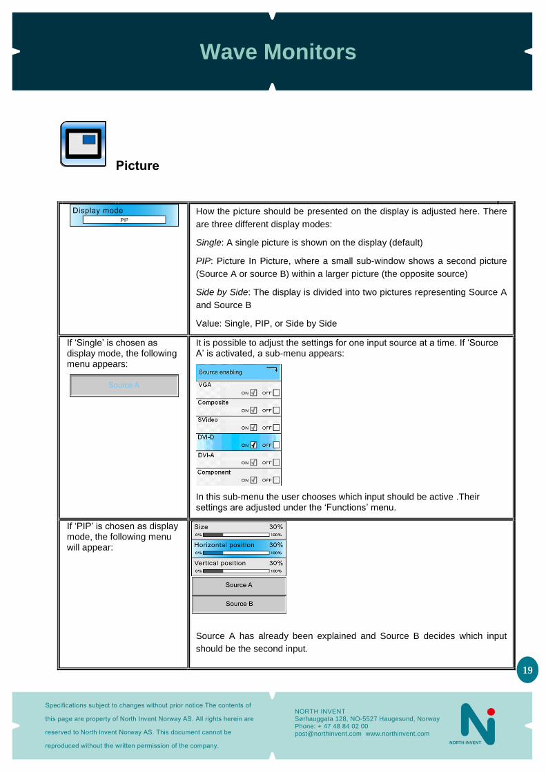
Picture
How the picture should be presented on the display is adjusted here. There
are three different display modes:
Single: A single picture is shown on the display (default)
PIP: Picture In Picture, where a small sub-window shows a second picture
(Source A or source B) within a larger picture (the opposite source)
Side by Side: The display is divided into two pictures representing Source A
and Source B
Value: Single, PIP, or Side by Side
If ‘Single’ is chosen as display mode, the following menu appears:
It is possible to adjust the settings for one input source at a time. If ‘Source A’ is activated, a sub-menu appears:
In this sub-menu the user chooses which input should be active .Their settings are adjusted under the ‘Functions’ menu.
If ‘PIP’ is chosen as display mode, the following menu will appear:
Source A has already been explained and Source B decides which input
should be the second input.
Wave Monitors
Specifications subject to changes without prior notice.The contents of
this page are property of North Invent Norway AS. All rights herein are
reserved to North lnvent Norway AS. This document cannot be
reproduced without the written permission of the company.
NORTH INVENT Sørhauggata 128, NO-5527 Haugesund, Norway Phone: + 47 48 84 02 00 [email protected] www.northinvent.com
20
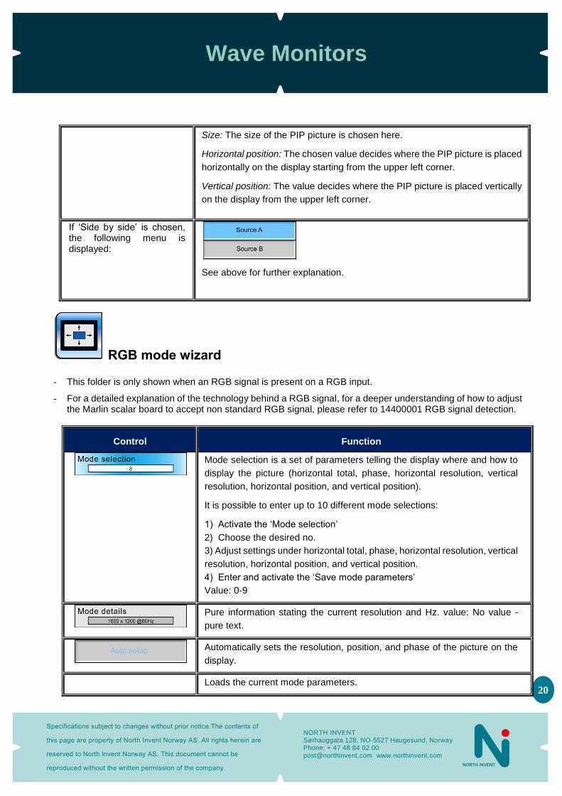
Size: The size of the PIP picture is chosen here.
Horizontal position: The chosen value decides where the PIP picture is placed
horizontally on the display starting from the upper left corner.
Vertical position: The value decides where the PIP picture is placed vertically
on the display from the upper left corner.
If ‘Side by side’ is chosen, the following menu is displayed:
See above for further explanation.
RGB mode wizard - This folder is only shown when an RGB signal is present on a RGB input.
- For a detailed explanation of the technology behind a RGB signal, for a deeper understanding of how to adjust the Marlin scalar board to accept non standard RGB signal, please refer to 14400001 RGB signal detection.
Control Function
Mode selection is a set of parameters telling the display where and how to
display the picture (horizontal total, phase, horizontal resolution, vertical
resolution, horizontal position, and vertical position).
It is possible to enter up to 10 different mode selections:
1) Activate the ‘Mode selection’
2) Choose the desired no.
3) Adjust settings under horizontal total, phase, horizontal resolution, vertical
resolution, horizontal position, and vertical position.
4) Enter and activate the ‘Save mode parameters’
Value: 0-9
Pure information stating the current resolution and Hz. value: No value -
pure text.
Automatically sets the resolution, position, and phase of the picture on the
display.
Loads the current mode parameters.
Wave Monitors
Specifications subject to changes without prior notice.The contents of
this page are property of North Invent Norway AS. All rights herein are
reserved to North lnvent Norway AS. This document cannot be
reproduced without the written permission of the company.
NORTH INVENT Sørhauggata 128, NO-5527 Haugesund, Norway Phone: + 47 48 84 02 00 [email protected] www.northinvent.com
21
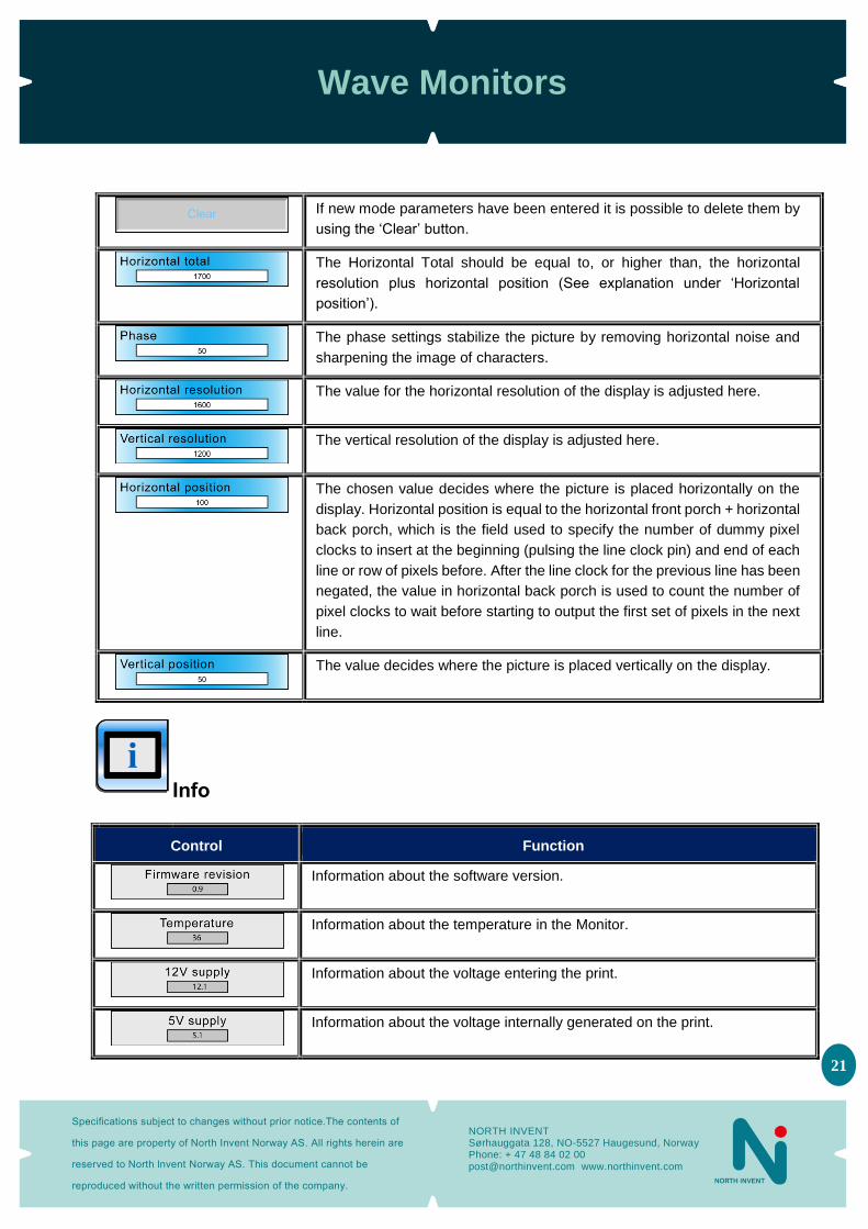
If new mode parameters have been entered it is possible to delete them by
using the ‘Clear’ button.
The Horizontal Total should be equal to, or higher than, the horizontal
resolution plus horizontal position (See explanation under ‘Horizontal
position’).
The phase settings stabilize the picture by removing horizontal noise and
sharpening the image of characters.
The value for the horizontal resolution of the display is adjusted here.
The vertical resolution of the display is adjusted here.
The chosen value decides where the picture is placed horizontally on the
display. Horizontal position is equal to the horizontal front porch + horizontal
back porch, which is the field used to specify the number of dummy pixel
clocks to insert at the beginning (pulsing the line clock pin) and end of each
line or row of pixels before. After the line clock for the previous line has been
negated, the value in horizontal back porch is used to count the number of
pixel clocks to wait before starting to output the first set of pixels in the next
line.
The value decides where the picture is placed vertically on the display.
Info
Control Function
Information about the software version.
Information about the temperature in the Monitor.
Information about the voltage entering the print.
Information about the voltage internally generated on the print.
Wave Monitors
Specifications subject to changes without prior notice.The contents of
this page are property of North Invent Norway AS. All rights herein are
reserved to North lnvent Norway AS. This document cannot be
reproduced without the written permission of the company.
NORTH INVENT Sørhauggata 128, NO-5527 Haugesund, Norway Phone: + 47 48 84 02 00 [email protected] www.northinvent.com
22
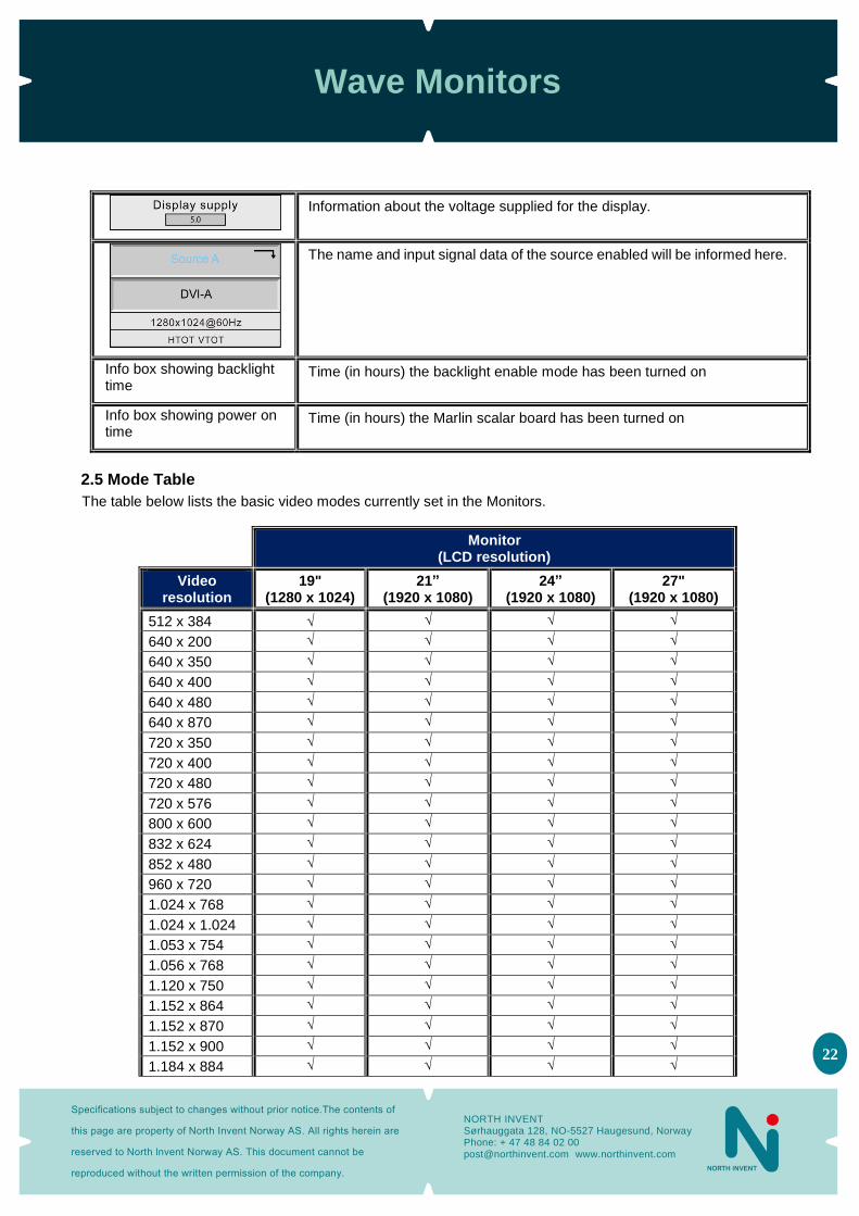
Information about the voltage supplied for the display.
The name and input signal data of the source enabled will be informed here.
Info box showing backlight time
Time (in hours) the backlight enable mode has been turned on
Info box showing power on time
Time (in hours) the Marlin scalar board has been turned on
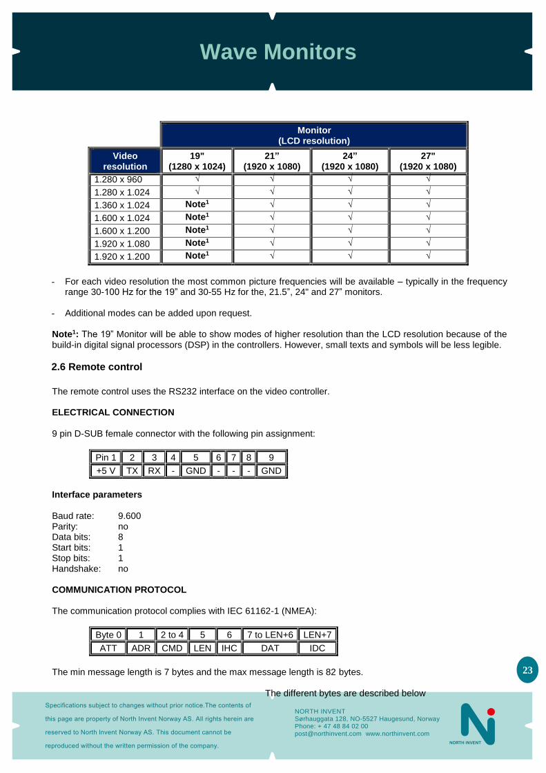
2.5 Mode Table
The table below lists the basic video modes currently set in the Monitors.
Monitor
(LCD resolution)
Video resolution
19" (1280 x 1024)
21” (1920 x 1080)
24” (1920 x 1080)
27" (1920 x 1080)
512 x 384 √ √ √ √
640 x 200 √ √ √ √
640 x 350 √ √ √ √
640 x 400 √ √ √ √
640 x 480 √ √ √ √
640 x 870 √ √ √ √
720 x 350 √ √ √ √
720 x 400 √ √ √ √
720 x 480 √ √ √ √
720 x 576 √ √ √ √
800 x 600 √ √ √ √
832 x 624 √ √ √ √
852 x 480 √ √ √ √
960 x 720 √ √ √ √
1.024 x 768 √ √ √ √
1.024 x 1.024 √ √ √ √
1.053 x 754 √ √ √ √
1.056 x 768 √ √ √ √
1.120 x 750 √ √ √ √
1.152 x 864 √ √ √ √
1.152 x 870 √ √ √ √
1.152 x 900 √ √ √ √
1.184 x 884 √ √ √ √
Wave Monitors
Specifications subject to changes without prior notice.The contents of
this page are property of North Invent Norway AS. All rights herein are
reserved to North lnvent Norway AS. This document cannot be
reproduced without the written permission of the company.
NORTH INVENT Sørhauggata 128, NO-5527 Haugesund, Norway Phone: + 47 48 84 02 00 [email protected] www.northinvent.com
23
Monitor
(LCD resolution)
Video resolution
19" (1280 x 1024)
21” (1920 x 1080)
24” (1920 x 1080)
27" (1920 x 1080)
1.280 x 960 √ √ √ √
1.280 x 1.024 √ √ √ √
1.360 x 1.024 Note1 √ √ √
1.600 x 1.024 Note1 √ √ √
1.600 x 1.200 Note1 √ √ √
1.920 x 1.080 Note1 √ √ √
1.920 x 1.200 Note1 √ √ √
- For each video resolution the most common picture frequencies will be available – typically in the frequency
range 30-100 Hz for the 19” and 30-55 Hz for the, 21.5”, 24" and 27” monitors.
- Additional modes can be added upon request. Note1: The 19” Monitor will be able to show modes of higher resolution than the LCD resolution because of the build-in digital signal processors (DSP) in the controllers. However, small texts and symbols will be less legible.
2.6 Remote control
The remote control uses the RS232 interface on the video controller. ELECTRICAL CONNECTION 9 pin D-SUB female connector with the following pin assignment:
Pin 1 2 3 4 5 6 7 8 9
+5 V TX RX - GND - - - GND
Interface parameters Baud rate: 9.600 Parity: no Data bits: 8 Start bits: 1 Stop bits: 1 Handshake: no COMMUNICATION PROTOCOL The communication protocol complies with IEC 61162-1 (NMEA):
Byte 0 1 2 to 4 5 6 7 to LEN+6 LEN+7
ATT ADR CMD LEN IHC DAT IDC
The min message length is 7 bytes and the max message length is 82 bytes.
The different bytes are described below

Wave Monitors
Specifications subject to changes without prior notice.The contents of
this page are property of North Invent Norway AS. All rights herein are
reserved to North lnvent Norway AS. This document cannot be
reproduced without the written permission of the company.
NORTH INVENT Sørhauggata 128, NO-5527 Haugesund, Norway Phone: + 47 48 84 02 00 [email protected] www.northinvent.com
24
Attention (ATT) byte This byte identifies the message start:
ATT Description
0x07 0x06 0x15
Command Acknowledge (OK) Acknowledge (error)
Address (ADR) byte
ADR Description
0xFF 0x00 0x01 - 0x0F
All controllers (0-15) Controller 0 Controller 1 etc. Controller 15
Command (CMD) bytes
CMD0 CMD1 CMD2 ASCII Description
0x42 0x4D 0x56 0x4D 0x54
0x52 0x41 0x45 0x43 0x59
0x54 0x4E 0x52 0x43 0x50
BRT MAN VER MCC TYP
Brightness Manufacturer Version (Monitor) Controller Type
Data length (LEN) byte Length of DAT in bytes (0-74 bytes) Inverse Header Checksum (IHC) byte It is a simple 8 bit checksum of the header data (bytes 0 to 5) where a bit-wise inversion has been performed. The checksum must be initialised to 0. The 8 bit sum (without carry) of bytes 0-6 must be 0xFF. IHC = 0xFF – (ATT+ADD+CMD0+COM1+COM2+LEN), where only 8 bits are used. If a message checksum fails the controller will reply with the attention byte 0x15 and no data bytes. Data (DAT) bytes The data bytes will only be send if data length (LEN) is greater than 0. The data bytes are designated DAT0, DAT1, DAT2, etc.
Wave Monitors
Specifications subject to changes without prior notice.The contents of
this page are property of North Invent Norway AS. All rights herein are
reserved to North lnvent Norway AS. This document cannot be
reproduced without the written permission of the company.
NORTH INVENT Sørhauggata 128, NO-5527 Haugesund, Norway Phone: + 47 48 84 02 00 [email protected] www.northinvent.com
25
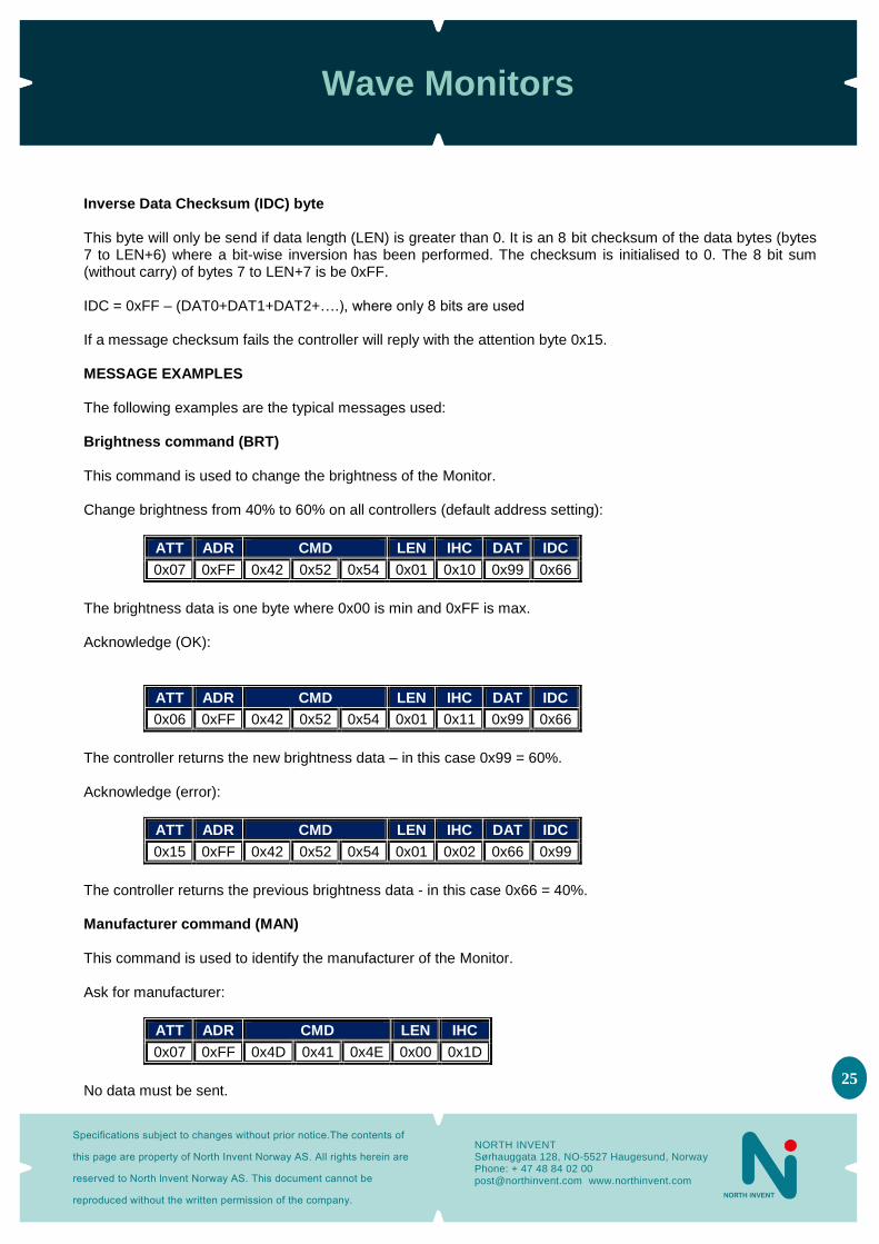
Inverse Data Checksum (IDC) byte This byte will only be send if data length (LEN) is greater than 0. It is an 8 bit checksum of the data bytes (bytes 7 to LEN+6) where a bit-wise inversion has been performed. The checksum is initialised to 0. The 8 bit sum (without carry) of bytes 7 to LEN+7 is be 0xFF. IDC = 0xFF – (DAT0+DAT1+DAT2+….), where only 8 bits are used If a message checksum fails the controller will reply with the attention byte 0x15. MESSAGE EXAMPLES The following examples are the typical messages used: Brightness command (BRT) This command is used to change the brightness of the Monitor. Change brightness from 40% to 60% on all controllers (default address setting):
ATT ADR CMD LEN IHC DAT IDC
0x07 0xFF 0x42 0x52 0x54 0x01 0x10 0x99 0x66
The brightness data is one byte where 0x00 is min and 0xFF is max. Acknowledge (OK):
ATT ADR CMD LEN IHC DAT IDC
0x06 0xFF 0x42 0x52 0x54 0x01 0x11 0x99 0x66
The controller returns the new brightness data – in this case 0x99 = 60%. Acknowledge (error):
ATT ADR CMD LEN IHC DAT IDC
0x15 0xFF 0x42 0x52 0x54 0x01 0x02 0x66 0x99
The controller returns the previous brightness data - in this case 0x66 = 40%. Manufacturer command (MAN) This command is used to identify the manufacturer of the Monitor. Ask for manufacturer:
ATT ADR CMD LEN IHC
0x07 0xFF 0x4D 0x41 0x4E 0x00 0x1D
No data must be sent.

Wave Monitors
Specifications subject to changes without prior notice.The contents of
this page are property of North Invent Norway AS. All rights herein are
reserved to North lnvent Norway AS. This document cannot be
reproduced without the written permission of the company.
NORTH INVENT Sørhauggata 128, NO-5527 Haugesund, Norway Phone: + 47 48 84 02 00 [email protected] www.northinvent.com
26
Acknowledge (OK):
ATT ADR CMD LEN IHC DAT IDC
0x06 0xFF 0x4D 0x41 0x4E 0x03 0x1B 0x4E 0x49 0x68
The controller returns the ASCII string value for the manufacturer – in this case NI (North Invent). Version command (VER) This command is used to identify the controller model and protocol version. Ask for model/version:
ATT ADR CMD LEN IHC
0x07 0xFF 0x56 0x45 0x52 0x00 0x0C
No data must be sent. Acknowledge (OK):
ATT ADR CMD LEN IHC DAT IDC
0x06 0xFF 0x56 0x45 0x52 0x03 0x0A 0x73 0x01 0x00 0x8B
The controller returns the controller model (DAT0) and protocol version (DAT1.DAT2) – in this case controller model 115 and protocol version 1.0. Controller command (MCC) This command is used for remote control of the display controller menu functions, e.g. the contrast settings. Ask for 50% contrast:
ATT ADR CMD LEN IHC DAT IDC
0x07 0xFF 0x4D 0x43 0x43 0x04 0x22 0x82 0x41 0x38 0x30 0xD4
The menu function is included in the data bytes:
DAT0 0x82 = contrast command
DAT1 0x41 = “a” = all colours
DAT2 0x38 = “8” = first digit of contrast value 0x80 = 50% of 0xFF
DAT3 0x30 = “0” = second digit of contrast value (se above)
Acknowledge (OK):
ATT ADR CMD LEN IHC DAT IDC
0x06 0xFF 0x4D 0x43 0x43 0x06 0x21 0x82 0x41 0x38 0x30 0x38 0x30 0x6C
The data field is extended with the new contrast values (DAT4 and DAT5).
Wave Monitors
Specifications subject to changes without prior notice.The contents of
this page are property of North Invent Norway AS. All rights herein are
reserved to North lnvent Norway AS. This document cannot be
reproduced without the written permission of the company.
NORTH INVENT Sørhauggata 128, NO-5527 Haugesund, Norway Phone: + 47 48 84 02 00 [email protected] www.northinvent.com
27
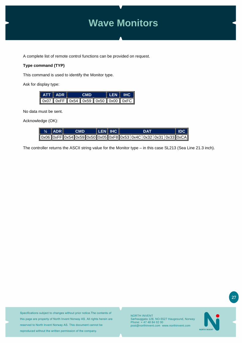
A complete list of remote control functions can be provided on request. Type command (TYP) This command is used to identify the Monitor type. Ask for display type:
ATT ADR CMD LEN IHC
0x07 0xFF 0x54 0x59 0x50 0x00 0xFC
No data must be sent. Acknowledge (OK):
½ ADR CMD LEN IHC DAT IDC
0x06 0xFF 0x54 0x59 0x50 0x05 0xF8 0x53 0x4C 0x32 0x31 0x33 0xCA
The controller returns the ASCII string value for the Monitor type – in this case SL213 (Sea Line 21.3 inch).

Wave Monitors
Specifications subject to changes without prior notice.The contents of
this page are property of North Invent Norway AS. All rights herein are
reserved to North lnvent Norway AS. This document cannot be
reproduced without the written permission of the company.
NORTH INVENT Sørhauggata 128, NO-5527 Haugesund, Norway Phone: + 47 48 84 02 00 [email protected] www.northinvent.com
28
3. Technical specifications
3.1 Summary
LVDS display 19” 21,5” 24” 27”
Max. resolution 1.280 x 1.024 1.920 x 1.080 1.920 x 1.080 1.920 x 1.080
Active area 376,32 x 301,06
mm 476,64 x 268,11
mm 531,36 x 289,89
mm 597,6 x 336,2 mm
Pixel pitch 0.294 x 0.294 mm 0.248 x 0.248 mm 0.277 x 0.277 mm 0.311 x 0.311 mm
Synchronisation Frequency
15-100 kHz(H), 30-100 Hz(V) up to 1.280x1.024 15-100 kHz(H), 30-55 Hz(V) up to 1.920x1.200
Contrast ratio 2000:1 5000:1 5000:1 3000:1
Brightness 300 cd/m² 300 cd/m² 300 cd/m² 300 cd/m²
Response time 20 ms 16 ms 25 ms 12 ms
Colours 16.7 Millions depending on graphics card
View angle ±89º ±89º ±89º ±89º
Backlight life Typ. 50,000 hours
Power supply Voltage
90-264 VAC, 18-36 VDC
Power Consumption 45W (AC) 45W (DC)
40W (AC) 40W (DC)
40W (AC) 40W (DC)
45W (AC) 45W (DC)
OSD Controls: Power, Brightness, Menu, Set, +, - & Lock with dimmable backlight Indicators: Input power AC & DC with LED
Input connectors DVI-I Female, D-SUB 15pin female, AC power IEC Inlet & DC screw terminal
Control Input RS232 D-SUB 9 pin female
Monitor Compatibility Plug & Play
Dimming range 0-100% (Dimming ratio 1000:1)
Operation Temperature -5°C/+55°C – +23°F /+131°F (IEC 60945)
Storage Temperature -25°C/+70°C - -13°F/+158°F
Glass Type Conturan© (Standard) Hardened, Laminated, anti-glare coated, all flush mounted
Colour of bezel Front and back: RAL 9005 structure.
Dimension & Weight (for consol mounting)
414x342x73,4 mm WxHxD
513,6x342x73,2mm WxHxD
574x341x73,2 mm WxHxD
632x375x73,4 mm WxHxD
Dimension & Weight (with hinge ex. HMI) Weight
414x377x73,4 mm WxHxD 7,9 Kg
513,6x377x73,2mm WxHxD 9,0 Kg
574x376x73,2 mm WxHxD 9,9 Kg
632x410 x73,4 mm WxHxD 10,7 Kg
Enclosure protection IP42 IP42 IP42 IP42
Standards & Approvals
IEC 60945, IEC 61174(ECDIS), IEC 60936(RADAR), IEC 62288, IEC 62388, IEC60529(IP), MIL-STD-810F, IACS E10 (ABS,BV,CCS,DNV,GL,KR, LR,NK,RINA,RS) approved by BSH.
Note: WA215 limited tests and approvals

Wave Monitors
Specifications subject to changes without prior notice.The contents of
this page are property of North Invent Norway AS. All rights herein are
reserved to North lnvent Norway AS. This document cannot be
reproduced without the written permission of the company.
NORTH INVENT Sørhauggata 128, NO-5527 Haugesund, Norway Phone: + 47 48 84 02 00 [email protected] www.northinvent.com
29
3.2 Firmware Revision table
Monitor Rev. Software Rev.
Description Date Signed by
01
3.3 Troubleshooting
- There are several possible solutions to the same problem – please try the first one on the list and then move
on to the next if the problem persists.
PROBLEM POSSIBLE SOLUTION
No AC or DC indication and no picture on the screen
Press the POWER control shortly, then press and hold the + control for a while
No AC or DC indication and no picture on the screen
Check the AC and/or DC power cable and make sure that voltage is present at the terminals
No picture on the screen but AC and/or DC indication is on
Press the + pad for full (brightness
No picture on the screen but AC and/or DC indication is on
Press the MENU control (or press and hold the LOCK control for 5 sec) and select the correct video source with the OSD
No picture on the screen but AC and/or DC indication is on
Check that a valid video signal is present on the selected source – use e.g. another Monitor
The picture do not fit the screen size Adjust the picture positions and frequency with the OSD
The picture cannot be adjusted to fit the screen size
Check if the video solution and frequency are included in the Mode Table above
The backlight cannot be adjusted from totally darkness to full brightness using the KNOB control
Adjust the backlight to 50 % with the OSD.
The backlight cannot be adjusted from totally darkness to full brightness using the remote control
Set the KNOB control in its calibrated setting (little mark above the KNOB)
Part of or whole picture is blurred Adjust the picture phase with the OSD
Wave Monitors
Specifications subject to changes without prior notice.The contents of
this page are property of North Invent Norway AS. All rights herein are
reserved to North lnvent Norway AS. This document cannot be
reproduced without the written permission of the company.
NORTH INVENT Sørhauggata 128, NO-5527 Haugesund, Norway Phone: + 47 48 84 02 00 [email protected] www.northinvent.com
30
3.4 Cleaning
- Dust and dirt which typically accumulates on the front of the Monitor, can easily be removed using a soft cloth
moistened with hot water. - A solvent can also be used but never use any kind of abrasive compound. - Oil and grease can be removed using pure alcohol. - The front glass can be cleaned with any solvent suitable for glass.
3.5 Update
- The technical documentation is subject to change. For an updated version please visit our website
www.northinvent.com.
4. Maintenance and service - Wave monitors are conceived so to be almost maintenance free. - If the Monitor malfunctions, please check if the problem can be solved with troubleshooting (3.3). - If the problem persists, please contact North Invent for service instructions.
Allow app. 1 hour stabilization time before measuring luminance and colors.
|
Wave
-UM
-Rev
1.1
-10
.2014