waveform multiplexing for 5g: a concept and 3d...
TRANSCRIPT

Waveform Multiplexing for 5G:A Concept and 3D Evaluation
Yeon-Geun Lim∗, Taehun Jung∗, Kwang Soon Kim†, and Chan-Byoung Chae∗∗School of Integrated Technology, †School of Electrical and Electronic Engineering, Yonsei University, Korea
Email: {yglim, taehun.jung, ks.kim, cbchae}@yonsei.ac.kr
Abstract—Fifth generation (5G) communication systems in-clude enhanced mobile broadband, massive machine-type com-munication, and ultra-reliable low-latency communication. Tosupport various 5G applications, researchers have consideredmultiple scalable subcarrier spacing and transmission time inter-val (TTI). In this paper, we introduce a concept of waveform mul-tiplexing for frequency multiplexing of numerologies. Waveformmultiplexing consists of different waveforms on subbands withscalable subcarrier spacing and TTI operating on one frequencyband. The Waveform multiplexing also possesses dynamic cyclicprefix and minimum guard band, which are the key featuresfor the high spectral efficiency. We verify the performance andthe potential of the waveform multiplexing using 3-dimensional(3D) ray-tracing based system-level evaluation in a realisticenvironment and a 3D channel.
Keywords—Multiplexing of numerologies, GFDM, filtered-OFDM, 3D channel model, 3D ray-tracing, system-level simulation,and 5G.
I. INTRODUCTION
In the recent years, researchers have discussed the potentialapplications of 5th generation (5G) communication. These areserviced along with other requirements for high capacity forenhanced mobile broadband (eMBB), massive machine-typecommunication (mMTC) connectivity, and ultra-reliable low-latency communication (URLLC) [1]. In the eMBB case, mas-sive multiple-input multiple-output (MIMO), full duplex, non-orthogonal multiple access (NOMA), mm-Wave, and small celltechniques have been extensively studied to enhance spectrumefficiency (bps/Hz), spectrum extension (Hz/cell), and networkdensity (cell/area). MIMO techniques have been evolved fromsingle user MIMO to multiuser MIMO [2]. The authors in[3] investigated performance of massive MIMO system witha lot of antennas at the BS and the large number of theserviced users. A full duplex system doubles its spectrum, andit was already prototyped in real time [4]. NOMA supportsusers simultaneously on the same resource in either a powerdomain or a code domain [5], [6]. Hybrid beamforming andelectromagnetic-lens antenna techniques have targeted mm-Wave and MIMO [7].
More recently, in trying to meet the various requirementsfor 5G applications, researchers have considered multiple scal-able subcarrier spacing and transmission time interval (TTI).The 3rd Generation Partnership Project (3GPP) has discussedsupporting, with various frequency bands, multiple sets ofsubcarrier spacing and of TTI. The development of techniquesto create high-capacity smart phones, an integrated deviceof applications requiring high data rates, has dominated the
mobile market of 4th generation (4G) long-term evolution(LTE) as a killer application. This is expected to continue in5G. It is quite possible that one of the 5G killer applicationscould be an integrated device or a central controller of variousapplications with other requirements, which could be operatedon one frequency band. To support such a device, 3GPPhas also discussed frequency multiplexing of numerologies.Meanwhile, it has not been determined which waveform willbe used and how this system is designed efficiently, yet.
3GPP agreed that new waveform of 5G will be basedon orthogonal frequency division multiplexing (OFDM) withfiltering or windowing. For example, the authors in [8], [9]proposed filtered OFDM (f-OFDM), which is integrated sys-tem of multiple independent OFDM systems with variousnumerologies based on subband-based splitting and filtering.The out-of-band emissions (OOBE) of each subband can besuppressed by a properly designed baseband finite impulseresponse (FIR) filter. Because of the suppression of OOBE,guard band usages can be reduced. On each subband, theoptimized numerology can be applied to fulfill requirementsof a certain type of the services so the various applicationscould be jointly provided with backward compatibilities.
However, there are still some potential new waveformcandidates that could support various applications includingnonorthogonal waveforms beyond the initial 5G system. Thesefulfill low OOBE and have robustness to asynchronous sys-tems. The authors proposed generalized frequency divisionmultiplexing (GFDM) [10], which divides time-frequency re-sources into blocks that consist of subsymbols and subcarriers.Adopting a circular pulse shaping filter, GFDM does notpresent filter tails, providing an advantage to low-latencyapplications. By choosing a well-localized pulse shaping fil-ter, OOBE can successfully be reduced. In the meantime,researchers have studied how to enable filter bank multicarrier(FBMC) to use quadrature amplitude modulation (QAM) andMIMO techniques in 5G [11]. The performance analysis ofeach waveform has been concentrated on link-level simulationmeasuring block error rate, OOBE, and overhead due to filterlength/cyclic prefix (CP).
To evaluate a system-level performance, researchers have,so far, compared techniques based on analysis in a 2-dimensional (2D) environment. In a conventional outdoormodel for system-level simulations, base stations (BSs), oneeach for three sectors, are placed at regular points following ahexagonal layout with a wrap-around configuration [12]. Inpractice, BSs and users are located in 3-dimensional (3D)space. As cell sizes have been shrinking with high network
978–1–5386–3873–6/17/$31.00 c© 2017 IEEE

Fig. 1. A block diagram of the proposed waveform multiplexing transmitter.
density, it could be important, when evaluating a 5G system,to measure the signal propagation at the elevation angles.The authors in [13] implemented a testbed of a 3D hybridbeamforming algorithm and measured its gain in a small cell.They showed the system-level performance of their algorithmusing a 3D ray-tracing tool based on measured data.
In this paper, we present a potential of a system that con-sists of different waveforms on each numerology. We name thisconcept waveform multiplexing. The waveform multiplexingcan be more efficiently operated than frequency multiplexingof numerology based on a single waveform. To evaluate howwell our waveform multiplexing performs, we must jointlycombine the link-level results into system-level simulations.We then propose a 3D channel model to evaluate system-level performances more practically by utilizing a realisticdigital map. The 3D system-level simulations confirm thatthe waveform multiplexing system outperforms an LTE-basedmulti-band OFDM system. According to both the OOBE andthe time overhead of the waveform candidates, the perfor-mances of the proposed waveform multiplexing vary in certainenvironments.
II. WAVEFORM MULTIPLEXING
A. A Concept of Waveform Multiplexing
As mentioned in Section I, 3GPP has discussed the fre-quency multiplexing of numerologies with the minimum guardband between numerologies. In this paper, we present a wave-form multiplexing technique as a system of the multiplexingof numerologies operating efficiently. We define waveformmultiplexing as a subband system having the following char-acteristics:
• Multiplexing of Waveforms on Subbands with Scal-able Subcarrier Spacing: One system supports various appli-cations such as eMBB, mMTC, and URLLC, on one frequencyband. Each subband consists of different waveforms withvarious subcarrier spacing. Unlike the f-OFDM system in [8],each subband can utilize different waveforms. This makes onesystem support multiple sets of symbol duration and TTI, andutilize appropriate waveform set.
• Dynamic CP: Thanks to the low OOBE of 5G waveformcandidates, the proposed waveform multiplexing can optimize amultiband system by employing different CP lengths. Conven-tional OFDM systems have strictly employed a fixed CP lengthso as to avoid destroying their orthogonality. The dynamic CP
technique has become essential as the cell size shirks and thedelay spread of each band varies.
• Minimum Guard Band between Subbands: Sinceguard band between the subbands can be minimized because ofthe low OOBE, 5G new waveform candidates promise higherspectrum usage than OFDM. In general, zero guard band hasbeen considered at the 3GPP meeting.
• Special Cases: The proposed concepts can cover severalspecial cases as a single waveform multiplexing. In [8], theOFDM system with scalable subcarrier spacing goes throughthe subband filter, and then they are mixed into an entire f-OFDM system. The authors in [14] managed to aggregate,with a single radio in the unlicensed bands, multiple subbands,which use different protocols at uplink or downlink. Thesecan also be viewed as a single waveform multiplexing of f-OFDM/OFDM.
B. Proposed Waveform Multiplexing Transceiver
In this section, we explain a generalized version of thewaveform multiplexing systems. For simplicity, we employtwo CP based waveform candidates.1 One is f-OFDM whichprovides much lower OOBE performance, so it can signifi-cantly reduce inter-subband interference. The other is GFDMwhich divides time-frequency resources into blocks that consistof subsymbols. Only a single CP is required for an entireGFDM symbol, which improves the spectral efficiency ofthe system. Detailed system parameters are given in Table I.Figure 1 illustrates a block diagram of the proposed waveformmultiplexing.2 In the ith subband transmitter, nsc,i × Mi m-QAM symbols are mapped to the Mi desired time grids andthe nsc,i desired frequency grids where m is the modulationorder. Each subband uses an appropriate subcarrier filter withNi size. If f-OFDM is used on the ith subband, the subcarrierfilter is a rectangular pulse easily implemented by an inversefast Fourier transform (FFT) filter where Mi = 1 and Nibecomes FFT size. If GFDM is used on the ith subband, eachsample passes through a corresponding subcarrier filter. Theseare time- and frequency-shifted versions of a prototype filter.A CP with ncp,i length, is added to the waveform symbol ofthe ith subband. Next, it passes through a subband filter, whichis a bandpass FIR filter in the f-OFDM case or a coefficient 1in the OFDM and GFDM case with time domain convolution.Finally, the baseband waveform signals are arranged accordingto the center frequencies of their subbands. The procedures atthe receiver are processed inversely. The GFDM receiver usesa post processing block such as zero-forcing to mitigate inter-carrier interference after subcarrier filtering, while OFDM/f-OFDM does not use this.
In fact, it is necessary to adjust the parameters of thewaveforms the proposed waveform multiplexing. This is be-cause the sampling rate per subband is the same. The numbersof subcarriers and subsymbols are depending on and limitedby a given subcarrier spacing with the fixed sampling rate.Moreover, the main concern with designing a GFDM system
1We do not employ FBMC since it do not use CP and has high complexityin the waveform multiplexing system.
2The proposed waveform multiplexing is one of waveform multiplexingsystems, i.e., any design satisfying the requirements explained in Section II-Acould be called as waveform multiplexing.
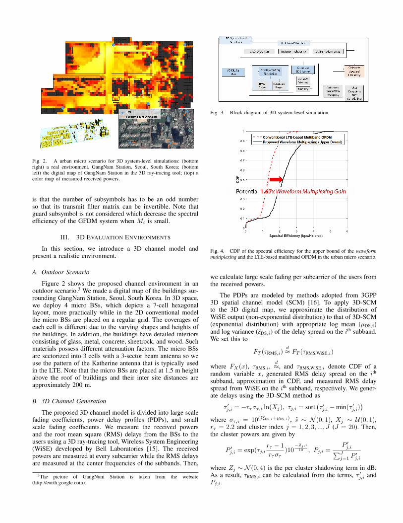
Fig. 2. A urban micro scenario for 3D system-level simulations: (bottomright) a real environment, GangNam Station, Seoul, South Korea; (bottomleft) the digital map of GangNam Station in the 3D ray-tracing tool; (top) acolor map of measured received powers.
is that the number of subsymbols has to be an odd numberso that its transmit filter matrix can be invertible. Note thatguard subsymbol is not considered which decrease the spectralefficiency of the GFDM system when Mi is small.
III. 3D EVALUATION ENVIRONMENTS
In this section, we introduce a 3D channel model andpresent a realistic environment.
A. Outdoor Scenario
Figure 2 shows the proposed channel environment in anoutdoor scenario.3 We made a digital map of the buildings sur-rounding GangNam Station, Seoul, South Korea. In 3D space,we deploy 4 micro BSs, which depicts a 7-cell hexagonallayout, more practically while in the 2D conventional modelthe micro BSs are placed on a regular grid. The coverages ofeach cell is different due to the varying shapes and heights ofthe buildings. In addition, the buildings have detailed interiorsconsisting of glass, metal, concrete, sheetrock, and wood. Suchmaterials possess different attenuation factors. The micro BSsare sectorized into 3 cells with a 3-sector beam antenna so weuse the pattern of the Katherine antenna that is typically usedin the LTE. Note that the micro BSs are placed at 1.5 m heightabove the roof of buildings and their inter site distances areapproximately 200 m.
B. 3D Channel Generation
The proposed 3D channel model is divided into large scalefading coefficients, power delay profiles (PDPs), and smallscale fading coefficients. We measure the received powersand the root mean square (RMS) delays from the BSs to theusers using a 3D ray-tracing tool, Wireless System Engineering(WiSE) developed by Bell Laboratories [15]. The receivedpowers are measured at every subcarrier while the RMS delaysare measured at the center frequencies of the subbands. Then,
3The picture of GangNam Station is taken from the website(http://earth.google.com).
Fig. 3. Block diagram of 3D system-level simulation.
Fig. 4. CDF of the spectral efficiency for the upper bound of the waveformmultiplexing and the LTE-based multiband OFDM in the urban micro scenario.
we calculate large scale fading per subcarrier of the users fromthe received powers.
The PDPs are modeled by methods adopted from 3GPP3D spatial channel model (SCM) [16]. To apply 3D-SCMto the 3D digital map, we approximate the distribution ofWiSE output (non-exponential distribution) to that of 3D-SCM(exponential distribution) with appropriate log mean (µDS,i)and log variance (ξDS,i) of the delay spread on the ith subband.We set this to
FT (τRMS,i)d≈ FT (τRMS,WiSE,i)
where FX(x), τRMS,i,d≈, and τRMS,WiSE,i denote CDF of a
random variable x, generated RMS delay spread on the ith
subband, approximation in CDF, and measured RMS delayspread from WiSE on the ith subband, respectively. We gener-ate delays using the 3D-SCM method as
τ ′j,i = −rτστ,i ln(Xj), τj,i = sort(τ ′j,i −min(τ ′j,i)
)where στ,i = 10(s̃ξDS,i+µDS,i), s̃ ∼ N (0, 1), Xj ∼ U(0, 1),rτ = 2.2 and cluster index j = 1, 2, 3, ..., J (J = 20). Then,the cluster powers are given by
P ′j,i = exp(τj,i
rτ − 1
rτστ)10
−Zj,i
10 , Pj,i =P ′j,i∑J
j=1 P′j,i
where Zj ∼ N (0, 4) is the per cluster shadowing term in dB.As a result, τRMS,i can be calculated from the terms, τ ′j,i andPj,i.

Fig. 5. Performance comparisons of waveform multiplexing sets: (a) CDF of the spectral efficiency for waveform multiplexing; (b) CDF of the spectral efficiencyassuming no intercell interference; (c) CDF of the spectral efficiency of the edge subcarriers.
TABLE I. SYSTEM PARAMETERS
Sampling Rate per Subband (MHz) 34.56System Bandwidth (MHz) 51.84Center Frequency (GHz) 5
Transmit Power of the Micro BS (dBm) 49 [16]Maximum Height of the Users 32.5 (on the 9th floor) [16]
Noise Floor (dBm/Hz) -174Backoff Calibration (dB) 5
Subband Index 1st 2nd 3rd
Subcarrier Spacing (kHz) 67.5 16.875 130Number of Subcarriers (Ki) 512 2048 256
Number of Allocated Subcarriers (nSC,i) 256 1024 128Subband Bandwidth (MHz) (∆i) 17.28 17.28 17.28
Center Frequency of Subband (GHz) (Fi) 4.98272 5.00000 5.01728CP length (nCP,i) 71 76 73
Subband filter Order (Li)/Number of Subsymbols (Mi)OFDM Set 0/1 0/1 0/1
f-OFDM Set 256/1 1024/1 128/1GFDM Set 0/3 0/1 0/7
WM-1 0/3 1024/1 0/7WM-2 256/1 1024/1 0/7
Lastly, we assume small-scale fading coefficients are com-plex Gaussian random variables with zero mean and unitvariance. Note that the proposed 3D channel model is realistic,since large scaling fading, OOBE propagations per subcarrierand PDPs are derived from the realistic environment andoutputs of the 3D ray-tracing tool.
IV. PERFORMANCE EVALUATION
In this paper, we present the waveform multiplexing ofthree subbands. In considering a downlink system, we assumeperfect channel estimation, frequency localization and timesynchronization to evaluate the best performance. We organizea total of 5 sets, made up of 3 single waveform multiplexingsets and 2 waveform multiplexing sets. As the single waveformmultiplexing set, we arrange (i) OFDM, (ii) f-OFDM, and (iii)GFDM with filter modifications, all of which have 3 subbandswith different subcarrier spacings. We also arrange a waveformset, (iv) {GFDM, f-OFDM, GFDM} with a subband set, {the1st subband, the 2nd subband, the 3rd subband}, which isdenoted as a waveform multiplexing set-1 (WM-1). We arrangeanother set, denoted as waveform multiplexing set-2 (WM-2)as follows, (v) {f-OFDM, f-OFDM, GFDM}.
A. Simulation Procedure
We investigate the data rate performance of the proposedwaveform multiplexing sets. We assume that the BSs and theusers are connected with point-to-point communication in afull buffer traffic scenario. The mobility of the users couldhave no effect on system performance (spectral efficiency) dueto perfect channel estimation, so we assume the mobilities ofall users to be zero. The users are uniformly distributed onthe ground and on every floor of the buildings, which arerandomly scheduled by the associated BS that provides thestrongest SNR. The users who require a long symbol durationsuch as LTE applications are supported on the 2nd subband,while the users requiring a short symbol duration, for exampleURLLC, and the in-between applications are serviced on the3rd and the 1st subbands, respectively. We also assume thatguard bandwidth is 0 Hz. The other system overhead aregiven by the overhead of the reference, common channels,synchronization, and physical broadcast channel = 4, 17, 0.29,and 0.28 percent, which are based on the LTE overhead.
In the f-OFDM system, we assume the transmitter useFIR bandpass filters of soft-truncated-sinc-function with theraised-cosine window and with 2.5 guard tones defined in[17]. In the GFDM system, the transmitter uses root-raised-cosine prototype filters with 0.1 of rolloff factor and thereceiver uses a zero-forcing filter. We assume that one slot foreach subband– the basic unit of the subframe at downlink–consists of 8 OFDM/f-OFDM symbols, similar to the LTEsystem. Similarly, one slot of GFDM for the 1st, the 2nd, andthe 3rd subbands consists of 9, 8, and 7 subsymbols (3, 8,and 1 symbols), respectively. From the slot organization, werecognize that each waveform has a different CP overhead.
Figure 3 illustrates the procedure for the 3D system-levelsimulations. We first generates the 3D channels as noted inSection III. The dynamic CP lengths are determined fromthe maximum delay spread for each subband. At the link-level simulator, we measure the probability of bit error ofthe waveforms under the generated 3D channels. We alsoevaluate the OOBE performance of the waveforms on eachsubband. Finally, we calculate spectral efficiency by combiningmeasurements such as SINR, the probability of bit error,OOBE, and so on.

B. Waveform Multiplexing Gain
Prior to the system-level simulation, we verify how muchthe proposed waveform multiplexing gains we can achievecompared to the conventional system. We assume the wave-form multiplexing has zero guard band, the optimal CP lengthper subband, and zero OOBE so that it can be consideredas the upper bound of every waveform multiplexing set. Wealso assume that the conventional system employs LTE-basedmultiband OFDM with 10 percent guard band, the LTE CPlength and −35 dB OOBE (not measured data). Figure 4illustrates the potential gain of the waveform multiplexing inthe urban micro environment. We confirm that the proposedwaveform multiplexing has 1.67 times larger gain than theconventional system at the median cumulative density function(CDF).
C. System-level Simulation Result
Figure 5 shows that the system-level performance com-parisons of the waveform multiplexing sets. In the urbanmicro environment, the performance of the sets of GFDM,WM-1, and WM-2 are close to the upper bound of theproposed waveform multiplexing as shown in Fig. 5(a). Thisis because that the CP overhead significantly affects on thespectral efficiency and the symbol transmit power, while theinfluence of the interference from the OOBE is less thanthat from the intercell (interference limited environments).In contrast, Fig. 5(b) shows that f-OFDM exhibits the bestperformance assuming no intercell interference (noise limitedenvironment) due to the lower OOBE. WM-1 and WM-2could, nonetheless, still serve as good options, consideringhow impractical too many high-order QAM techniques are.Figure 5(c) illustrates that WM-1 and WM-2 outperform theothers at the edge subcarriers (2 subcarriers per subband nearthe adjacent subband) in the interference limited environment.Note that the waveform multiplexing with multiple waveformscould have a better spectrum usage than the single waveformmultiplexing schemes by choosing a efficient waveform foreach subband. From the evaluation results, we confirm thatthe systems consisting of different waveforms have betterperformance than the systems based on a single waveform.
V. CONCLUSION
This paper has presented a potential of a system thatconsists of different waveforms on each numerology, whichis a waveform subband system operated on one frequencyband. We have named this concept waveform multiplexing.To support various applications for 5G, the waveform multi-plexing possesses three characteristics including multiplexingof waveforms on subbands with scalable subcarrier spacing,dynamic CP, and minimum guard band. Based on the 3D ray-tracing evaluation under the realistic environment, GangNamStation, and the proposed 3D channel, we have evaluated thesystem-level performances of the proposed waveform mul-tiplexing. The performances vary in a certain environmentaccording to both the OOBE and the time overhead of thewaveform candidates. From the results, we have confirmedthat the waveform multiplexing, which consists of differentwaveforms on subbands, have strong potential in the systemof frequency multiplexing of numerologies. In future work,we will investigate agile spectrum-sharing by utilizing the
proposed waveform multiplexing and uplink waveform mul-tiplexing. Considering more subband filtering and windowingtechniques will also be our future work.
ACKNOWLEDGMENT
This research was supported by the MSIP (Ministry ofScience, ICT and Future Planning), Korea, under the “IT Con-silience Creative Program” (IITP-2017-0-01015) supervisedby the IITP (Institute for Information & CommunicationsTechnology Promotion) and ICT R&D program of MSIP/IITP(2015-0-00300).
REFERENCES
[1] G. Wunder, P. Jung, M. Kasparick, T. Wild, F. Schaich, Y. Chen, S. T.Brink, I. Gaspar, N. Michailow, A. Festag, L. Mendes, N. Cassiau,D. Ktenas, M. Dryjanski, S. Pietrzyk, B. Eged, P. Vago, and F. Wied-mann, “5GNOW: non-orthogonal, asynchronous waveforms for futuremobile applications,” IEEE Commun. Mag., vol. 52, no. 2, pp. 97–105,Feb. 2014.
[2] D. Gesbert, M. Kountouris, R. W. Heath, Jr., C.-B. Chae, and T. Salzer,“Shifting the MIMO paradigm: From single user to multiuser commu-nications,” IEEE Sig. Proc. Mag., vol. 24, no. 5, pp. 36–46, Oct. 2007.
[3] Y.-G. Lim, C.-B. Chae, and G. Caire, “Performance analysis of mas-sive MIMO for cell-boundary users,” IEEE Trans. Wireless Commun.,vol. 14, no. 12, pp. 6827–6842, Dec. 2015.
[4] M. Chung, M. Sim, J. Kim, D.-K. Kim, and C.-B. Chae, “Prototypingreal-time full duplex radios,” IEEE Commun. Mag., vol. 53, no. 9, pp.56–64, Sep. 2015.
[5] Y. Saito, Y. Kishiyama, A. Benjebbour, T. Nakamura, A. Li, andK. Higuchi, “Non-orthogonal multiple access (NOMA) for cellularfuture radio access,” in Proc. IEEE VTC Spring, June 2013, pp. 1–5.
[6] H. Kim, Y.-G. Lim, C.-B. Chae, and D. Hong, “Multiple access for 5Gnew radio: Categorization, evaluation, and challenges,” arXiv preprintarXiv: 1703.09042, Mar. 2017.
[7] T. Kwon, Y.-G. Lim, B. Min, and C.-B. Chae, “RF lens-embeddedmassive MIMO systems: Fabrication issues and codebook design,” IEEETrans. Microw. Theory Tech., vol. 64, no. 7, pp. 2256–2271, July 2016.
[8] X. Zhang, M. Jia, L. Chen, J. Ma, and J. Qiu, “Filtered-OFDM - enablerfor flexible waveform in the 5th generation cellular networks,” in Proc.IEEE Globecom, Dec. 2015, pp. 1–6.
[9] J. Abdoli, M. Jia, and J. Ma, “Filtered OFDM: A new waveform forfuture wireless systems,” in Proc. IEEE Int. Workshop on SPAWC, June2015, pp. 66–70.
[10] N. Michailow, M. Matth, I. S. Gaspar, A. N. Caldevilla, L. L. Mendes,A. Festag, and G. Fettweis, “Generalized frequency division multi-plexing for 5th generation cellular networks,” IEEE Trans. Commun.,vol. 62, no. 9, pp. 3045–3061, Sept. 2014.
[11] B. Farhang-Boroujeny, “OFDM versus filter bank multicarrier,” IEEESig. Proc. Mag., vol. 28, no. 3, pp. 92–112, May 2011.
[12] ITU-R Rep. M.2135-1, Guidelines for evaluation of radio interfacetechnologies for IMT-Advanced, Dec. 2009.
[13] J. Jang, M. Chung, H. Hwang, Y.-G. Lim, H. Yoon, T. Oh, B. Min,Y. Lee, K. Kim, C.-B. Chae, and D.-K. Kim, “Smart small cellwith hybrid beamforming for 5G: Theoretical feasibility and prototyperesults,” IEEE Wireless Commun. Mag., vol. 23, no. 6, pp. 124–131,Dec. 2016.
[14] S. Hong, J. Mehlman, and S. Katti, “Picasso: flexible RF and spectrumslicing,” in Proc. ACM SIGCOM, Oct. 2012, pp. 37–48.
[15] R. Valenzuela, D. Chizhik, and J. Ling, “Measured and predictedcorrelation between local average power and small scale fading inindoor wireless communication channels,” in Proc. IEEE VTC Spring,vol. 3, May 1988, pp. 2104–2108.
[16] 3GPP TR 38.873 V12.2.0, Study on 3D channel model for LTE, June2015.
[17] 3GPP R1-165425, “f-OFDM scheme and filter design,” Huawei, HiSil-icon, May 2016.