wc-8c vertical coolant circulator - esabna.com equipment/mechanized plasma... · wc-8c vertical...
TRANSCRIPT
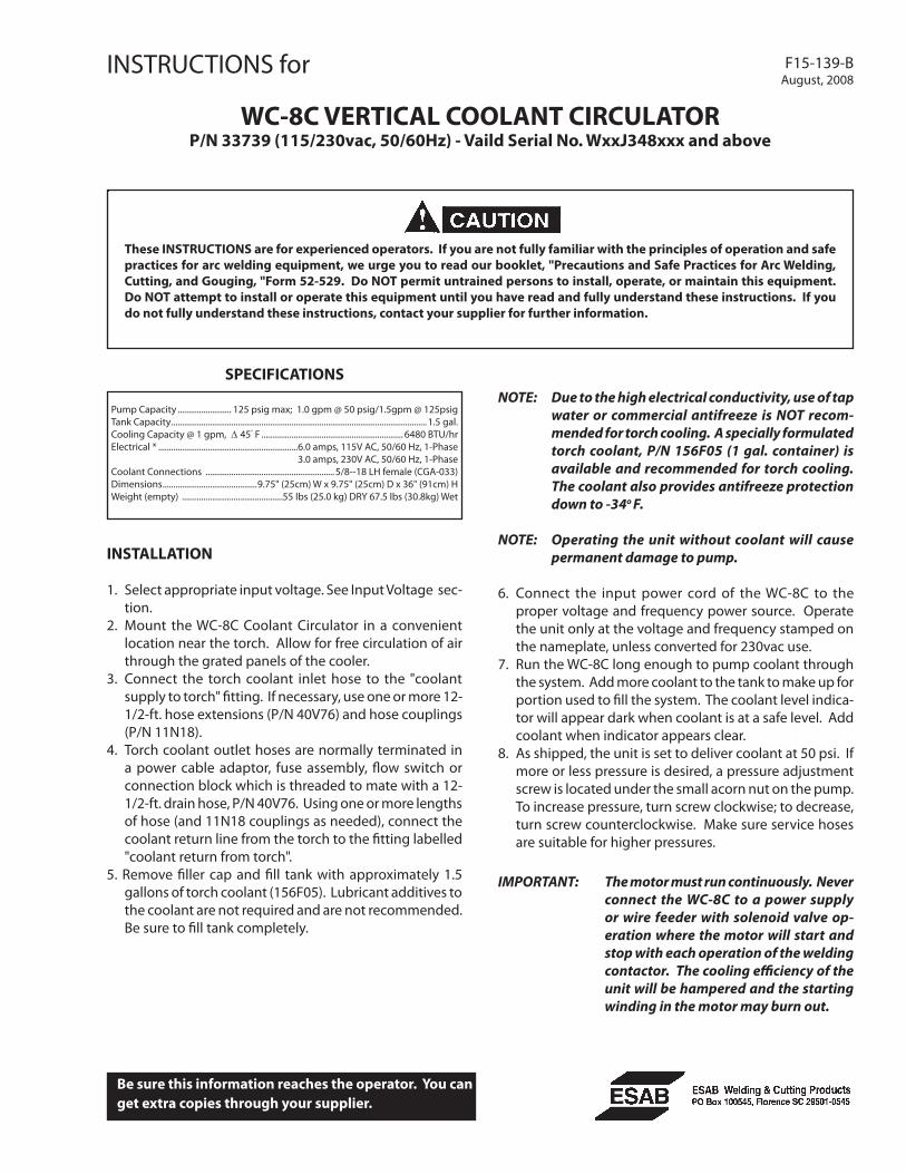
INSTRUCTIONS for F15-139-BAugust, 2008
WC-8C VERTICAL COOLANT CIRCULATORP/N 33739 (115/230vac, 50/60Hz) - Vaild Serial No. WxxJ348xxx and above
INSTALLATION
1. Select appropriate input voltage. See Input Voltage sec-tion.
2. Mount the WC-8C Coolant Circulator in a convenient location near the torch. Allow for free circulation of air through the grated panels of the cooler.
3. Connect the torch coolant inlet hose to the "coolant supply to torch" fitting. If necessary, use one or more 12-1/2-ft. hose extensions (P/N 40V76) and hose couplings (P/N 11N18).
4. Torch coolant outlet hoses are normally terminated in a power cable adaptor, fuse assembly, flow switch or connection block which is threaded to mate with a 12-1/2-ft. drain hose, P/N 40V76. Using one or more lengths of hose (and 11N18 couplings as needed), connect the coolant return line from the torch to the fitting labelled "coolant return from torch".
5. Remove filler cap and fill tank with approximately 1.5 gallons of torch coolant (156F05). Lubricant additives to the coolant are not required and are not recommended. Be sure to fill tank completely.
.
Be sure this information reaches the operator. You can get extra copies through your supplier.
These INSTRUCTIONS are for experienced operators. If you are not fully familiar with the principles of operation and safe practices for arc welding equipment, we urge you to read our booklet, "Precautions and Safe Practices for Arc Welding, Cutting, and Gouging, "Form 52-529. Do NOT permit untrained persons to install, operate, or maintain this equipment. Do NOT attempt to install or operate this equipment until you have read and fully understand these instructions. If you do not fully understand these instructions, contact your supplier for further information.
SPECIFICATIONS
Pump Capacity ......................... 125 psig max; 1.0 gpm @ 50 psig/1.5gpm @ 125psigTank Capacity .......................................................................................................................1.5 gal.Cooling Capacity @ 1 gpm, ∆ 45° F .................................................................. 6480 BTU/hrElectrical * .................................................................6.0 amps, 115V AC, 50/60 Hz, 1-Phase 3.0 amps, 230V AC, 50/60 Hz, 1-PhaseCoolant Connections ............................................................5/8--18 LH female (CGA-033)Dimensions ............................................9.75" (25cm) W x 9.75" (25cm) D x 36" (91cm) HWeight (empty) ...............................................55 lbs (25.0 kg) DRY 67.5 lbs (30.8kg) Wet
NOTE: Due to the high electrical conductivity, use of tap water or commercial antifreeze is NOT recom-mended for torch cooling. A specially formulated torch coolant, P/N 156F05 (1 gal. container) is available and recommended for torch cooling. The coolant also provides antifreeze protection down to -34o F.
NOTE: Operating the unit without coolant will cause permanent damage to pump.
6. Connect the input power cord of the WC-8C to the proper voltage and frequency power source. Operate the unit only at the voltage and frequency stamped on the nameplate, unless converted for 230vac use.
7. Run the WC-8C long enough to pump coolant through the system. Add more coolant to the tank to make up for portion used to fill the system. The coolant level indica-tor will appear dark when coolant is at a safe level. Add coolant when indicator appears clear.
8. As shipped, the unit is set to deliver coolant at 50 psi. If more or less pressure is desired, a pressure adjustment screw is located under the small acorn nut on the pump. To increase pressure, turn screw clockwise; to decrease, turn screw counterclockwise. Make sure service hoses are suitable for higher pressures.
IMPORTANT: The motor must run continuously. Never connect the WC-8C to a power supply or wire feeder with solenoid valve op-eration where the motor will start and stop with each operation of the welding contactor. The cooling efficiency of the unit will be hampered and the starting winding in the motor may burn out.

2
MAINTENANCE
ELECTRIC SHOCK CAN KILL. Precautionary measures should be taken to provide maximum protection against electrical shock. Be sure that all primary power to the machine has been externally disconnected. Open wall disconnect switch or circuit breaker before attempting inspection or work inside the circulator. Install all covers after completing service. Do not operate unit without covers. If this equipment does not operate properly, stop work immediately and investigate the cause of the malfunction. Maintenance work must be performed by an experienced person, and electrical work by a trained electrician. Do not permit untrained persons to inspect, clean, or repair this equipment. Use only recommended replacement parts.
If this equipment does not operate properly, stop work immediately and investigate the cause of the malfunction. Maintenance work must be performed by an experienced person, and electrical work by a trained electrician. Do not permit untrained persons to inspect, clean, or repair this equipment. Use only recommended replacement parts.
1. Maintain coolant level by observing the indicator win-dow. When dark, coolant is at a safe level; when clear, add more coolant.
2. Periodically remove the large 15/16" acorn nut from the pump and check the filter screen (19972) for sediment. Clean the filter or replace if necessary.
3. Periodically empty and flush the reservoir.4. To insure optimum performance of the circulator, remove dust from the radiator by means of compressed
air.5. The motor is equipped with a thermal overload protec-
tion. If motor stops, switch power off and wait at least 5 minutes. Then switch power on. If motor runs, the motor was shut off by the thermal overload protection. If it does not run, then check motor for damage.
6. Oil both motor bearings (yellow oil plug) once a year for heavy usage with SAE 20 oil.
TROUBLESHOOTING
1. Pump Below Capacity - Can be caused by restricted inlet, wrong direction of rotation, low motor R.P.M., and the relief valve improperly adjusted.
2. Pump Noisy - Can be caused by restricted inlet, dis- charge pressure over 125 P.S.I., loose acorn nut or damaged acorn nut gasket, air getting into lines, loose couplings, misalignment between pump and motor, and loose mounting bolts or clamping ring.
3. Leakage - Is caused by failing mechanical shaft seal or rubber O-rings. Arrange to have pump rebuilt.
4. Pump Turns Hard - Can be caused by misalignment be-tween pump and motor or by lime and mineral deposits in the pump. Deposits in pump would necessitate a pump rebuild, arrange to have pump rebuilt.
5. Motor No Turning - Check to see if circuit breaker tripped. Motor may be overheated. Allow to cool with power removed from unit for at least 5 minutes.
6. Do not disassemble pump! Any attempt at field repair will void the warranty.
As shipped, the unit is assembled for 115 vac. 50/60 Hz use. To use with 208-230 vac, 50/60 Hz input, the motor electri-cal connections and inlet plug must be changed. See Data Plate located on the motor for electrical connections.
Connection notes for Coolant Circulators equipped with Emerson pump motor
model # CO55JXGFR-3591 only.
115V Factory shipped 208-230V
Note: Location #6 is not an electrical connection. It is used to secure the brown wire to prevent possible shorting, for the high voltage configuration.
INPUT VOLTAGE SELECTION
If ESAB Coolant Circulator is equipped with a motor from an alternate manufacturer refer
to Motor Data Plate for electrical connec-tions.

33
Fig.
1 -
WC
-8C
REP
LAC
EMEN
T PA
RTS
GA
UG
E -
0558
0044
88

In AUSTRALIA
ROEHLEN INDUSTRIES PTY. LTD.P. O. Box 354Mordialloc, Victoria 3195Ph. No. 61 (3) 580-4155Fax No. 61 (3) 580-2954
In JAPAN
NIPPON OIL PUMP COMPANY, LTD.1 Chome No. 8-2, HorinouchiSuginami-Ku, TokyoPh. No. 81-03-(313) 7521Fax no. 81-03-(313) 2188
In GERMANY
STANDEX INTERNATIONAL GMBHPostfach 1306654150 Krefeld (formerly W. Germany)Ph. No. 49 (2151) 371224Fax no. 49 (2151) 371258 REPLACEMENT PARTSReplacement Parts are illustrated in Figure 1. When ordering replacement parts, order by part number and part name, as illustrated on the figure. DO NOT ORDER BY PART NUMBER ALONE.
Always provide the series or serial number of the unit on which the parts will be used. The serial number is stamped on the unit nameplate.
To assure proper operation, it is recommended that only genuine ESAB parts and products be used with this equip-ment. The use of non-ESAB parts may void your warranty.
Replacement parts may be ordered from your ESAB dis-tributor or from:
ESAB Welding & Cutting ProductsAttn: Customer Service DepartmentP. O. Box 100545, Ebenezer RoadFlorence, S.C. 29501-0545
Be sure to indicate any special shipping instructions when ordering replacement parts.
To order parts by phone, contact ESAB at 1-803-664-5540 or 4460. Orders may also be faxed to 1-800-634-7548. Be sure to indicate any special shipping instructions when ordering replacement parts.
F15-139-B
PUMP SERVICE CENTERSArrange to have the pump serviced, when necessary at one of the following service centers. Rebuilt and exchange pumps as well as new pumps carry a one year manufac-turer’s warranty.
In the U.S.A.
PROCON PRODUCTS (Manufacturer)910 Ridgely RoadMurfreesboro, TN 37130Ph. No. (615) 890-5710
HALSTED & HOGGAN INC.935 Santa Fe AvenueLos Angeles, CA 90021Ph. No. (213) 623-1248
FOXX EQUIPMENT COMPANY955 Decatur, Unit BDenver, CO 80204Ph. No. (303) 573-1766
AMERICAN BEVERAGE EQUIPMENT COMPANY27560 Grosesbeck Hwy.Roseville, MI 48066Ph. No. (313) 773-0094
FOXX EQUIPMENT COMPANY421 Southwest Blvd.Kansas City, MO 64108Ph. No. (816) 421-3600CHUDNOW MANUFACTURING COMPANY, INC.3055 New StreetOceanside, NY 11572Ph. No. (516) 593-4222
NORTHLAKE SUPPLY COMPANY1347 Manufacturing StreetDallas, TX 75207Ph. No. (214) 653-8381
SOUTHWEST BOTTLERS1360 Presidential DriveSuite 120Richardson, TX 75081Ph. No. (214) 235-8768
RESTAURANT APPLIANCE SERVICE7219 Roosevelt Way NESeattle, WA 98115Ph. No. (206) 524-8200