we build a better future! - Главная...
TRANSCRIPT


Based on state-of-the-art manufacturing facility and continuously developedtechnology, Hyundai has been manufacturing Synchronous Alternators for itsmarine and industrial customers throughout the world for the past 25 years.Our customers have come to rely on our strict quality control procedures andon-time delivery programs.
Hyundai Marine-purpose Generators have been widely acknowledged not onlyby major world classification societies such as LRS of U.K., ABS of U.S.A., DNVof Norway, GL of Germany, NK of Japan, CCS China KR of Korea, but also byleading shipowners around the world.
Hyundai’s quality control system is certified to conform to the Quality ControlSystem Standard (ISO 9001) and the Environmental Management Systemcertification (ISO14001).
Hyundai Synchronous Alternators have long been recognized for theirdependability and have been playing a significant role in the world’s marinevessels and power industries. Hyundai will continue to produce uniqueproduct innovations through continuous product research and development.
Electrical Constant voltage excitation with rapid dynamic voltage response
MechanicalTERMINAL BOX can be located in the alternator frame at left or right side as required
EXCITATION SYSTEM are mounted inside of protective housing
Maintenance Easier maintenance with brushless excitation
Due to continuous development the technical data are subject to change without prior notice.
Three-Phase Brushless
Synchronous Alternators

04 Constant Voltage Brushless Synchronous Alternators06 Technical Data08 Mechanical Data10 Performance Data12 Special Provisions for Marine Alternators14 Notes for The Selection of Alternators16 Selection Tables24 Dimension Tables
C o n t e n t s
We build a better future!

Three-Phase B
rushlessSynchronous Alternators
Constant Voltage Brushless Synchronous Alternators
04
ApplicationThe constant voltage brushless synchronous
alternator is of a self-excited type with an
electronic voltage regulator integrated in the
excitation unit.
It is used as main and standby units for land
based power installations and for marine
electrical supplies. Units can be driven by
internal combustion engines, gas, steam or
water turbines and electric motors.
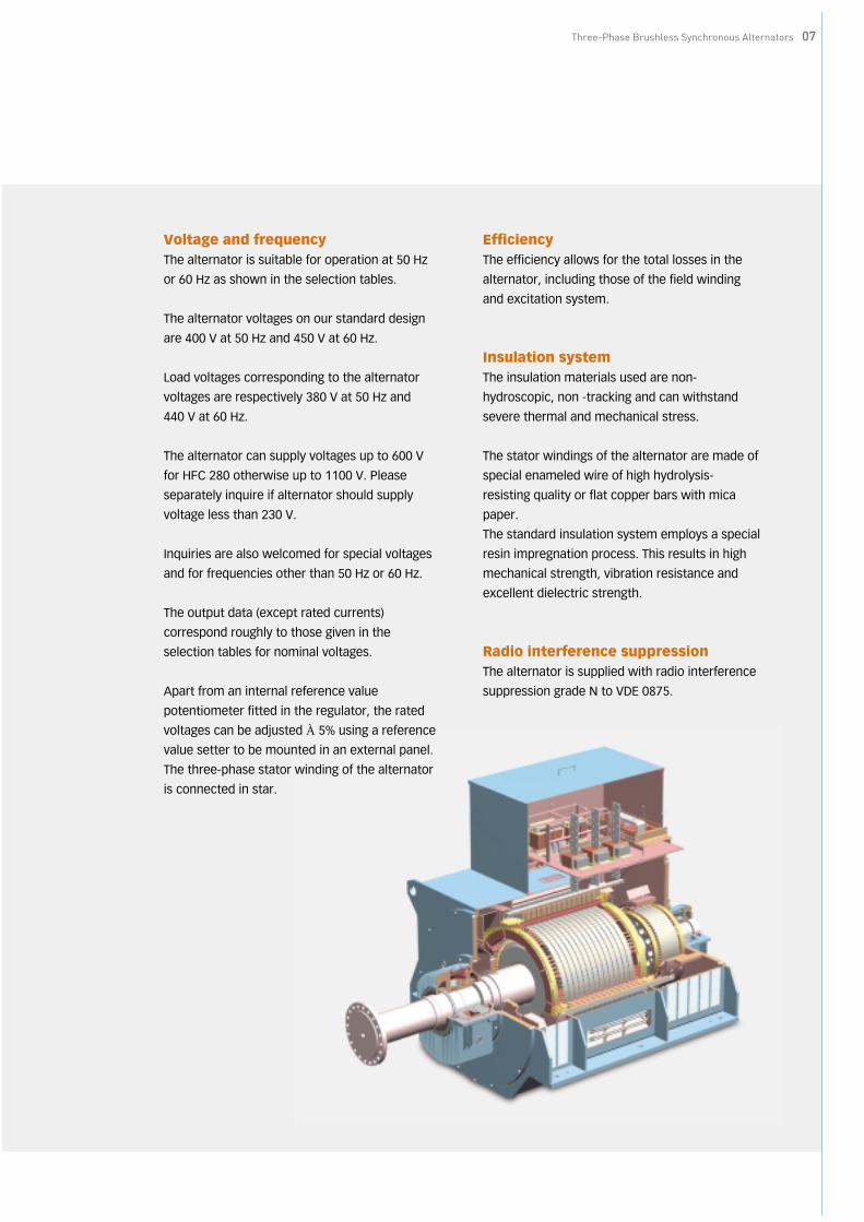
ConstructionThe alternator comprises the main machine
(revolving field machine with cylindrical rotor
and damper winding), exciter (revolving
armature machine) and excitation equipment.
The excitation power is supplied to the rotor of
the main machine via rotating rectifiers.
For type of cooling, see page 08.
Excitation systemThe alternator is fitted according to size and
type with an excitation system with THYRIPART
excitation system (load dependent excitation,
compounded with thyristor voltage regulator).
This method results in excellent dynamic
response to load switching applications and
short circuits.
Standards and codes of practiceThe alternator conforms to the applicable IEC
requirements, DIN standards and VDE codes,
particularly to VDE 0530 specification for
rotating electrical machines.
Other standards on inquiry.

Three-Phase Brushless Synchronous Alternators 05

Three-Phase B
rushlessSynchronous Alternators
Technical Data
OutputThe rated outputs (kVA) given in the selection
tables see(page 16~23) are valid for
■continuous duty at 50 or 60 Hz rated frequency
■power factors from 0.8 to 1 (LAGGING)
■class F insulation
■sinusoidal load current
■symmetrical load
Site rated outputA deduction must made from the nominal
output to VDE 0530 (rated output at 40℃ and
1000 m above sea level) in each of the
following cases:
1. Coolant temperature exceeds 40℃ and all
practices for marine alternators not
complying with classification society rules
(see the selection tables).
A special inquiry should be made if the
coolant temperature exceeds 55℃.
At a coolant temperature of 30℃, the mean
output is increased by 4% over that
permissible at 40℃.
2. Site altitude exceeds 1000 m above sea level
(applicable for in-land power installations only)
If no coolant temperature is stated, it will be
assumed that the altitude-induced reduction in
the cooling efficiency is compensated by a
lower coolant temperature, i.e. adjustment of
the maximum temperature rise to VDE 0530 is
not necessary (no de-rating).
The following coolant temperatures have been
obtained for the thermal utilization
corresponding to Class F insulation:
3. Power factor <0.8
4. Unbalanced load (see page 11)
5. Overload (see page 11; for marine alternators
page 12)
6. Slight voltage dip when large loads like
squirrel-cage motors are switched in (see
page 10).
7. Load current is not sinusoidal in case of
static converter load (please inquire).
Site altitude Permissible outputm a. s. l. % of rated value
1000 100
1500 97
2000 94
2500 91
3000 87
3500 82
4000 77
cos phi Permissible output
Power facto % of rated valueHFC5 HFC6
0.8...11) 100 100
0.7 95 96
0.6 91 92
0.5 89 91
0.4 87 90
0.0 84 88
Altitude in m a.s.l.:
1000 1500 2000 2500 3000 3500 4000
Coolant temperature in ℃:
40 35 30 25 19 14 9
1) A shaft end of large diameter may be required forHFC5-alternators when the power factor is greaterthan 0.8.
06
Three-Phase Brushless Synchronous Alternators 07
Voltage and frequencyThe alternator is suitable for operation at 50 Hz
or 60 Hz as shown in the selection tables.
The alternator voltages on our standard design
are 400 V at 50 Hz and 450 V at 60 Hz.
Load voltages corresponding to the alternator
voltages are respectively 380 V at 50 Hz and
440 V at 60 Hz.
The alternator can supply voltages up to 600 V
for HFC 280 otherwise up to 1100 V. Please
separately inquire if alternator should supply
voltage less than 230 V.
Inquiries are also welcomed for special voltages
and for frequencies other than 50 Hz or 60 Hz.
The output data (except rated currents)
correspond roughly to those given in the
selection tables for nominal voltages.
Apart from an internal reference value
potentiometer fitted in the regulator, the rated
voltages can be adjusted ±5% using a reference
value setter to be mounted in an external panel.
The three-phase stator winding of the alternator
is connected in star.
EfficiencyThe efficiency allows for the total losses in the
alternator, including those of the field winding
and excitation system.
Insulation systemThe insulation materials used are non-
hydroscopic, non -tracking and can withstand
severe thermal and mechanical stress.
The stator windings of the alternator are made of
special enameled wire of high hydrolysis-
resisting quality or flat copper bars with mica
paper.
The standard insulation system employs a special
resin impregnation process. This results in high
mechanical strength, vibration resistance and
excellent dielectric strength.
Radio interference suppressionThe alternator is supplied with radio interference
suppression grade N to VDE 0875.
Three-Phase B
rushlessSynchronous Alternators
Mechanical Data
Speed and direction of rotationAt the rated speed given in the selection tables,
the alternator produces the rated frequency of
50 Hz or 60 Hz.
The alternator is designed for clockwise
rotation, when viewed from the drive-end if not
otherwise specified. It can also be made for
counterclockwise rotation.
In accordance with VDE 0530, the sequence “U,
V, W” of the terminals in the terminal box
corresponds to the phase sequence in
clockwise rotation. For parallel operation with
an existing system, the phase sequence must
be checked before making the connections.
Overspeed for alternators is normally specified
to be nmax =1.2 x nN. Higher values on request.
With the alternator main switch open, there is
no restriction on operating the alternator with
THYRIPARTⓇ - excitation at less than rated
speed (like in the case of starting up the prime
mover).
This does not apply to special alternators with
sleeve bearings which may only be run at a
reduced speed to about 20% of their rated
speed.
Types of constructionThe alternator can be supplied in the following
versions to IEC 34-7 (IM=international
mounting).
For the different types of construction other
than those illustrated below, please inquire.
Degree of protectionThe alternator normally has the degree of
protection IP 23 (IEC 34-5) if not specified
otherwise.
The HFJ7 45. to 56. series have IP44/IC81W
according to IEC.
The HFJ7 63. to 80. have IP44/IC81 in
accordance with IEC (IC81: closed circuit
cooling system with air/water cooler mounted).
See page 13.
The terminal box or terminal space has the
degree of protection IP54.
Other degree of protection on inquiry.
Air filterAir filter can be provided in HFC7 series for
special conditions (on request).
If the design calls for air filter, it is
recommended that temperature sensors be
fitted in the stator winding so that the
alternator can be immediately alarmed or
tripped in case of abnormal temperature rise
due to a dirty filter.
Anti-condensation heatingAnti-condensation heating is available for the
alternator.
The supply voltage to the anti-condensation
heater must be 220 V or 110 V of single phase.
Terminals and connection bus barsCable entry to the main connections (U,V,W)
and 2 field terminals (+F1, -F2) can be made at
the left or right side as instructed. The cable
entry plates are normally supplied undrilled.
IM 1101 IM 1001 IM 1305(B20) (B3) (B16)
HFC7 HFC7 HFC7 HFJ7 HFJ7 HFJ7
08
Three-Phase Brushless Synchronous Alternators 09
Moment of inertiaAll values for the moment of inertia (J in kg- m2)
given in the selection tables are subject to a
tolerance of ±10% to VDE 0530.
The values are for the rotor without coupling.
CoolingThe HFC7 series are internally cooled with shaft-
mounted fan to VDE 0530, IC 01 to IEC. The fan
provided at the drive-end draws the cooling air
axially through the machine.
For details of air inlet and discharge openings,
see the dimension tables.
Noise emissionThe noise level of the alternator will not exceed
that specified in Part 9, VDE 0530 (1981).
Vibration stabilityReciprocating engines used as prime mover
impress vibrations on the alternator because of
the pulsating torque output.
Permissible vibration stress measured at the
bearings is
Please inquire if higher vibration strees level are
expected.
BearingsIf required, alternators with HFC7 453 and above
can be fitted with sleeve bearings at extra cost.
Alternators with HFC7 63. - 80. for marine use
are generally fitted with sleeve bearings.
Alternators with HFC7 350 and above a miniature
Pt 100 screw-in resistance thermometer can be
fitted in the bearings for remote display
(optional).
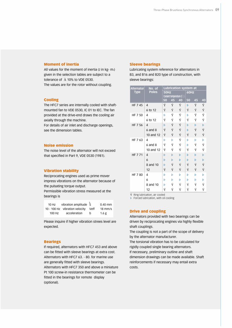
Sleeve bearingsLubricating system reference for alternators in
B3, and B16 and B20 type of construction, with
sleeve bearings:
Drive and couplingAlternators provided with two bearings can be
driven by reciprocating engines via highly flexible
shaft couplings.
The coupling is not a part of the scope of delivery
by the alternator manufacturer.
The torsional vibration has to be calculated for
rigidly coupled single bearing alternators.
If necessary, preliminary outline and shaft
dimension drawings can be made available. Shaft
reinforcements if necessary may entail extra
costs.
〈10 Hz vibration amplitude S ≦ 0.40 mm10 - 100 Hz vibration velocity Veff ≦ 18 mm/s〉100 Hz acceleration b ≦ 1.6 g
∧
AlternatorType
No. ofPoles
Lubrication system at50Hz 60HzCoolant temperature (℃ )50 45 40 50 45 40
HF 7 45 4 ○ ○ ○ ● ○ ○
6 to 12 ○ ○ ○ ○ ○ ○
HF 7 50 4 ● ○ ○ ● ○ ○
6 to 12 ○ ○ ○ ○ ○ ○
HF 7 56 4 ● ○ ○ ● ● ●
6 and 8 ○ ○ ○ ● ○ ○
10 and 12 ○ ○ ○ ○ ○ ○
HF 7 63 4 ● ● ○ ● ● ●
6 and 8 ○ ○ ○ ● ○ ○
10 and 12 ○ ○ ○ ○ ○ ○
HF 7 71 4 ● ● ● ● ● ●
6 ● ● ● ● ● ●
8 and 10 ● ○ ○ ○ ○ ○
12 ○ ○ ○ ○ ○ ○
HF 7 80 4 ● ● ● ● ● ●
6 ● ● ● ● ● ●
8 and 10 ● ○ ○ ○ ○ ○
12 ○ ○ ○ ○ ○ ○
○ Ring lubrication, air cooled● Forced lubrication, with oil cooling

Three-Phase B
rushlessSynchronous Alternators
Performance Data
Steady state voltage variationThroughout the range from no-load to rated
load at rated power factor, the following voltage
regulating accuracies are achieved
The voltage variation of alternators with droop
compensation device can be improved to that of
isolated operation value by short-circuiting the
droop compensation devices, while not in
parallel operation.
Calculation exampleIt is assumed that three-phase induction motor
with squirrel-cage rotor maybe switched on to
an unloaded brushless constant voltage
synchronous alternator.
Generator Data
Motor Data
Momentary voltage drop caused by starting of
load is calculated by the following formula;
NoteIf the voltage variation exceeds the given value, the load is tobe reduced by an appropriate starting circuit with inductionmotors; otherwise, a larger frame size of alternator isnecessary.
Short-circuit current and short- circuit ratingOwing to the load dependent operation of the
static excitation system, the alternator meets
the requirements for the lowest possible
voltage dips and rapid voltage recovery (like in
case of sudden loading with large squirrel-cage
induction motors).
The excitation principle employed features
sustained short-circuit currents of
approximately 3 to 5 times of the rated current.
This enables the use of selective protective
relays. The alternator must be relieved from the
sustained short-circuit current in 5 seconds.
THYRIPARTexcitation
Isolated operation(without droop compensation device) UN±0.5%
Parallel operation(with droop compensation device) UN±2.5%
Alternator type HFC7 504-10
Capacity 880 KVA
PF 0.8
Voltage 450 V
X’d 28.2%=0.282 pu.
X’’d 15.1%=0.151 pu.
Capacity 170 kW
PF 88.5%
Efficiency 93.5%
Nominal Current(In) 269.6 A
Starting Current(Is) 760% at direct on line starting
Starting Method Auto-TR 65% tap starting
※Calculation of starting capacity of largest motor 90kW
=√3×voltage×starting current
=√3×0.44×(269.9×7.6×0.65^2)
≒660 [KVA]
Generator reactance (X’’’D)
X’’’D = 0.282+0.151 = 0.21652
Formula for calculating starting load reactance XL ;
XL = generator capacity starting capacity of thrown-on load
= 880 ≒ 1.334660
Voltage drop △V is calculated by the following formula ;
△V = X’’’D ×100X’’’D + XL
= 0.2165 ×1000.2165 + 1.334
≒14%
△V : Allowable momentary voltage drop
(Max. - 15% according to LRS requirement)
X’D : Direct-axis transient reactance of generator
X’’D : Direct-axis sub-transient reactance of generator
10

Three-Phase Brushless Synchronous Alternators 11
Unbalanced loadIn accordance with VDE 0530, the alternator can
withstand unbalanced loading of up to 20%.
It should be noted, however, that the voltage
variation and the rated outputs indicated in the
tables are not attained under unbalanced load.
OverloadIn accordance with VDE 0530, the alternator can
have an overload of 1.5 times of the rated
current at rated voltage for 2 minutes.
The alternator has been designed to match the
overload capabilities of diesel engines. For one
hour out of every 6 hours, the alternator can
supply 110% of rated power without harmful
overheating. (Also see page 09, overload data for
marine alternators.)
Parallel operationDuring such a short period for no break load
transfer, alternators can be operated in parallel
regardless of design variants and manufacturer.
Continuous parallel operation between HFC7 and
HFJ7 alternators is possible, provided that
following points be fulfilled:
1. All alternators equipped with damper
windings which reduce phase swinging in
parallel operation
2. Active load sharing controlled with the
governor of the driving engine. The speed
characteristics of the engine should be linear,
turing change-over from rated load to no-load
and the speed variation should fall between 3
to 5% of the rated speed
3. Reactive load sharing assured by droop
compensation or cross current compensation
device
A droop compensation device can be fitted into
the main body for HFC7 280 to 356 if requested
(extra cost) and is also available for HFC7 40 to
HFC7 80.
Owing to the droop compensation device
provided, alternators are suitable for parallel
operation with other alternators, having the
same voltage droop or supply system.
Neutral point connectionDirect interconnection of alternator neutrals
and/or those of transformers and load neutrals
may give rise to circulating current by three
times of the power frequency in the neutral
conductors.
The magnitude of these currents must be
measured in the alternator neutral conductors
under the highest conceivable load condition.
To avoid thermal overloading of the alternators
the circulating currents occurring at three times
of the rated frequency should not exceed about
50% of the alternator rated current. Higher
current values should be limited by means of
neutral reactors or other equivalent means.
Protection equipmentThe stator winding can be provided with thermal
protection in the form of PTC sensors or
resistance thermometers (optional).
Please inquire when alternator protection gear
necessitates opening of neutral. Please indicate
type designation if it is intended to use a star-
point current transformer.
Alternators to be operated in parallel should be
provided with reverse power protection.
The necessary monitoring and tripping devices
must be provided separately and are not
included in the alternator scope of supply.

Three-Phase B
rushlessSynchronous Alternators
Special Provisions for Marine Alternators
12
In addition to compliance with the standards
and codes quoted on page 03, HFC7 and HFJ7
marine alternators also conform to the
requirements of the following classification
societies:
Marine alternators can also meet the
requirements of other classification societies
such as
Polish Register of Shipping (PRS)Russian Maritime Register ofShippingIn case of shaft alternators (driven by the main
engine of turbine), attention must be paid to
the special speed characteristics and to the
excess torque protection, if applicable Please
inquire for further information.
Works inspection and acceptanceMarine alternators are subject to works
inspection and acceptance as stipulated in the
table below:
Alternator intended particularly for ship’s
propulsion system are subject to works
inspection and acceptance test, irrespective of
the output rating.
Overload requirements (Also refer to Overload, page 09.)
American Bureau of Shipping ABS 45, 50
Bureau Veritas BV 45, 50
China Classification Society CCS 45, 50
Det Norske Veritas DNV 45
Germanischer Lloyd GL 45
Korean Register of Shipping KR 45, 50
Lloyd’s Register of Shipping LRS 45, 50
Registro Italiano Navale RINa 45, 50
Classification society AbbreviationCoolant
temperature(CT)℃
Abbreviation Work inspection AcceptanceABS ≧100 kW ≧100 kWBV ≧100 kW allGL — ≧50 kVALRS, RINa ≧100 kW ≧100 kWDNV all all
VDE 150 2 min -
ABS 150 30 sec no overload capability specified
125 2 h1) upon owner’s request only; steady-state temperature rise
from previous oper-ation not to be more than 15K
BV 150 2 min at p.f.0.6 (lagging)
GL 110 2 min at p.f.0.5 (lagging)
LRS 150 15 sec -
DNV 150 30 sec only for alternators at p.f.0.6 and rated frequency
RINa 150 2 min at p.f.0.6 (lagging)
Rules Overload current in % of rated current
Overloadduration Remarks
During overload testing, the voltage must be kept as close as possible to its rated value.
1) The rated output given in the selection tables is to be reduced to 88%.

Three-Phase Brushless Synchronous Alternators 13
Air/water coolerIf required HFJ7 45. to 80. alternators can be
supplied with a top-mounted air/water cooler.
The cooler can be used for fresh water or
seawater and can be made of double-or single-
tube type.
The type designation for the alternator with
air/water cooler is HFJ. Due to the closed-circuit
cooling system, the degree of protection has
been upgraded from IP23 to IP44.
The electrical particulars of the alternators with
air/water cooler remain unchanged.
The alternator HFJ can easly be converted for
emergency operation as an open circuit air-
cooled machine if the coolant system of the
cooling element fails. In such a case, the degree
of protection is IP23 with the rated output
maintained.
Please always provide the following information
for any inquiry:
■Coolant temperature (air)
■Cooling water inlet temperature
■Fresh water or seawater
■Type of cooler (single or double tube)
Classification society rules
ABS
GL
LRS
For alternators with a total
weight (less shaft) of more than
1000 1bs (~450kg) applicable
for HFC7 280 and above
For alternators with 500 kVA
and above
For alternators with 500 kVA
and above
Resistance thermometer to measure the
temperature of stator winding for the output of 500
kVA and above
Temperature sensors in the stator winding for
alternators with air filters; thermometer in the
cooling air circuit and a temperature sensor in the
stator with air/water cooler; bearing thermometer
for sleeve bearings; alarm device for excessive
temperature rise in bearing with external lubrication
Temperature sensor in the cooling air circuit for
alternators with air/ water cooler.
Classificationsociety
Anti-conden sation heating 1)
(Also see page 08.)Thermometer
Temperature sensor (See page 12, protectionequipment.)
1) It is always recommended that alternators for emergency and port use be ordered with anti-condensation heater,regardless of the classification society rules.
Three-Phase B
rushlessSynchronous Alternators
Notes for The Selection of Alternators
14
Standard design of the alternatorBrushless
THYRIPARTⓇ - excitation with thyristor regulator
Class F insulation
Radio interference suppression N to VDE 0875
Main terminals (U , V, W)
Cable entry plate undrilled
Type of construction;
IM B5/20 with HFC7 18. to 40.
IM B3 with HFC7 45. to 56. and HFC7 63. to 80.
IM B20 with HFC7 45. to 56. and HFC7 63. to 80.
Flange and shaft extensions to DIN
Degree of protection IP23.
Antifriction bearings (sleeve bearing for marine
alternators ; HFJ7 and HFC7)
Damper winding
Droop compensation (built-in)
for HFC7 40. to 56.and HFC7 63. to 80.
Optional accessories and variations to standard design■Reference value setter (for control pannel)
■3 or 6 PTC temperature sensors
(alarm and/or trip)
■3 resistance thermometers Pt 100
(6 thermometers for HFC7 350 and above)
■Radio interference suppression grade K to
VDE 0875
■Anti-condensation heater
■Miniature Pt 100 screw-in resistance
thermometers for bearing installation for
HFC7 350 and above
■Droop compensation
■Star-point current transformers for HFC7 45.
to 56. and HFC7 63. to 80.
■Air filter
■Air/water cooler for HFJ7 45. to 56. and HFJ7
63. to 80.
Spare partsRecommended spare for stock purpose
■Bearing or bearing shells for sleeve bearing
(as applicable)
■Rotating rectifier stack
■Rectifiers for the excitation equipment
■Voltage regulator
Determination of output and current
Pa =S· cos phi·100
η
S =Pa·η
cos phi·100
I = S·1000
√3·U
Pa : Power input in kW
I : Current in A
S : Alternator output in kVA
η: Efficiency in %
U : Voltage in V
(Also refer to site rated output, page 06.)

Three-Phase Brushless Synchronous Alternators 15
Selection Tables450/260 V, 60 Hz
-1800 rev/min (4-pole)
-1200 rev/min (6-pole)
-900 rev/min (8-pole)
-720 rev/min (10-pole)
400/231 V, 50 Hz
-1500 rev/min (4-pole)
-1000 rev/min (6-pole)
-750 rev/min (8-pole)
-600 rev/min (10-pole)
Dimension Tables HFC7 280 to HFC7 406
HFC7 454 to HFC7 806
HFJ7 564 to HFJ7 806

Selection Tables 450/260 V, 60 Hz 1800 rev/min (4-pole)
16
Three-Phase B
rushless Synchronous Alternators
Rated output at p.f.0.8 to 1.0and coolant temperature (CT)…℃
Column1 2 3 4
CT℃ ℃ ℃ ℃ Rules40 45 50 55 VDE
40 45 KR- - - 50 ABS- 40 45 50 BV
40 45 - - GL- 40 45 50 LRS
35 - 45 - DNV- 45 50 - RINa
kVA kVA kVA kVA kg kg m2 A
1800 rev/min (4-pole) IP23
130 125 120 118 HFC7 280-4 700 1.98 167
170 160 155 150 282 710 2.07 218
210 205 200 195 284 920 3.01 269
255 250 235 230 286 930 3.20 327
310 300 290 280 HFC7 350-4 1,220 4.3 398
350 340 330 320 352 1,280 4.6 449
445 435 425 415 354 1,400 5.2 571
560 530 515 500 356 1,600 6.4 718
570 560 545 525 HFC7 400-4 1,750 9.1 731
650 620 600 585 402 1,820 9.6 834
690 660 630 605 404 1,910 10.9 885
740 710 680 650 406 1,955 11.4 949
1,015 970 945 925 HFC7 454-4 3,000 29.0 1,302
1,230 1,170 1,135 1,105 456 3,100 32.0 1,578
1,390 1,340 1,300 1,270 HFC7 502-4 3,350 34.0 1,783
1,620 1,570 1,530 1,500 504 3,600 37.0 2,078
1,770 1,690 1,640 1,600 506 3,800 40.0 2,271
2,245 2,130 2,075 2,025 HFC7 564-4 4,650 54.1 2,880
2,450 2,400 2,345 2,290 566 5,300 59.5 3,143
2,645 2,590 2,535 2,475 568 5,700 63.0 3,394
2,810 2,725 2,640 2,555 HFC7 632-4 6,980 94.0 3,605
3,285 3,190 3,085 3,000 634 7,400 102.0 4,215
3,710 3,605 3,490 3,380 636 7,950 109.0 4,760
3,905 3,785 3,670 3,555 HFC7 710-4 8,800 155.0 5,010
Net Moment of Rated currentWeight inertia (J) at 450 V, 60 Hz
B16approx. approx.

Selection Tables 450/260 V, 60 Hz 1200 rev/min (6-pole)
Three-Phase Brushless Synchronous Alternators 17
Rated output at p.f.0.8 to 1.0and coolant temperature (CT)…℃
Column1 2 3 4
CT℃ ℃ ℃ ℃ Rules40 45 50 55 VDE
40 45 KR- - - 50 ABS- 40 45 50 BV
40 45 - - GL- 40 45 50 LRS
35 - 45 - DNV- 45 50 - RINa
kVA kVA kVA kVA kg kg m2 A
1200 rev/min (6-pole) IP23
205 200 195 190 HFC7 350-6 1,160 4.3 263
250 245 240 235 352 1,250 5.8 321
290 285 280 275 354 1,400 7.8 372
400 390 380 370 356 1,460 8.5 513
520 510 500 490 HFC7 404-6 1,810 11.8 667
645 635 625 615 406 2,010 14.1 828
765 745 725 705 HFC7 454-6 2,810 19.6 981
890 870 850 830 456 2,960 22.7 1,142
1,230 1,205 1,180 1,155 HFC7 502-6 3,350 32.8 1,578
1,360 1,330 1,300 1,270 504 3,600 37.2 1,745
1,565 1,535 1,505 1,475 506 4,000 43.2 2,008
1,710 1,680 1,650 1,620 508 4,300 45.5 2,194
1,870 1,830 1,785 1,740 HFC7 564-6 4,900 63.1 2,399
1,940 1,900 1,860 1,840 566 5,200 68.8 2,489
2,100 2,050 2,000 1,950 568 5,400 72.0 2,694
2,700 2,620 2,540 2,450 HFC7 634-6 7,200 146 3,464
3,060 2,980 2,895 2,810 636 7,600 157 3,926
3,230 3,140 3,050 2,955 638 7,800 162 4,144
3,500 3,400 3,300 3,200 HFC7 712-6 9,100 226 4,491
3,900 3,800 3,700 3,580 714 9,700 245 5,004
4,400 4,300 4,200 4,090 716 10,500 277 5,645
Net Moment of Rated currentWeight inertia (J) at 450 V, 60 Hz
B16approx. approx.

Selection Tables 450/260 V, 60 Hz 900 rev/min (8-pole)
18
Three-Phase B
rushless Synchronous Alternators
Rated output at p.f.0.8 to 1.0and coolant temperature (CT)…℃
Column1 2 3 4
CT℃ ℃ ℃ ℃ Rules40 45 50 55 VDE
40 45 KR- - - 50 ABS- 40 45 50 BV
40 45 - - GL- 40 45 50 LRS
35 - 45 - DNV- 45 50 - RINa
kVA kVA kVA kVA kg kg m2 A
900 rev/min (8-pole) IP23
670 635 620 605 HFC7 454-8 3,000 29 860
725 685 670 655 456 3,100 32 930
865 820 800 780 HFC7 502-8 3,350 39 1,110
1,025 975 950 925 504 3,600 43.5 1,315
1,250 1,190 1,160 1,130 506 3,800 47.9 1,604
1,380 1,310 1,280 1,250 508 4,100 52.5 1,771
1,570 1,500 1,450 1,415 HFC7 564-8 5,060 92.0 2,014
1,670 1,600 1,545 1,505 566 5,244 96.2 2,143
1,840 1,790 1,730 1,690 568 5,428 102.0 2,361
1,940 1,885 1,825 1,765 HFC7 634-8 6,528 144 2,489
2,385 2,310 2,240 2,170 636 6,720 166 3,060
2,465 2,390 2,315 2,240 638 7,008 180 3,163
3,025 2,930 2,840 2,750 HFC7 712-8 9,200 241 3,881
3,455 3,350 3,245 3,145 714 9,500 266 4,433
3,885 3,765 3,650 3,535 716 9,900 300 4,984
4,445 4,305 4,180 4,045 HFC7 802-8 12,100 440 5,703
5,125 5,040 4,890 4,730 804 13,100 510 6,575
5,895 5,770 5,600 5,420 806 14,500 585 7,563
Net Moment of Rated currentWeight inertia (J) at 450 V, 60 Hz
B16approx. approx.
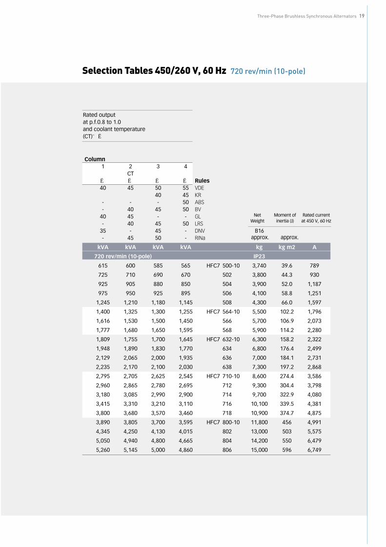
Selection Tables 450/260 V, 60 Hz 720 rev/min (10-pole)
Three-Phase Brushless Synchronous Alternators 19
Rated output at p.f.0.8 to 1.0and coolant temperature (CT)…℃
Column1 2 3 4
CT℃ ℃ ℃ ℃ Rules40 45 50 55 VDE
40 45 KR- - - 50 ABS- 40 45 50 BV
40 45 - - GL- 40 45 50 LRS
35 - 45 - DNV- 45 50 - RINa
kVA kVA kVA kVA kg kg m2 A
720 rev/min (10-pole) IP23
615 600 585 565 HFC7 500-10 3,740 39.6 789
725 710 690 670 502 3,800 44.3 930
925 905 880 850 504 3,900 52.0 1,187
975 950 925 895 506 4,100 58.8 1,251
1,245 1,210 1,180 1,145 508 4,300 66.0 1,597
1,400 1,325 1,300 1,255 HFC7 564-10 5,500 102.2 1,796
1,616 1,530 1,500 1,450 566 5,700 106.9 2,073
1,777 1,680 1,650 1,595 568 5,900 114.2 2,280
1,809 1,755 1,700 1,645 HFC7 632-10 6,300 158.2 2,322
1,948 1,890 1,830 1,770 634 6,800 176.4 2,499
2,129 2,065 2,000 1,935 636 7,000 184.1 2,731
2,235 2,170 2,100 2,030 638 7,300 197.2 2,868
2,795 2,705 2,625 2,545 HFC7 710-10 8,600 274.4 3,586
2,960 2,865 2,780 2,695 712 9,300 304.4 3,798
3,180 3,085 2,990 2,900 714 9,700 322.9 4,080
3,415 3,310 3,210 3,110 716 10,100 339.5 4,381
3,800 3,680 3,570 3,460 718 10,900 374.7 4,875
3,890 3,805 3,700 3,595 HFC7 800-10 11,800 456 4,991
4,345 4,250 4,130 4,015 802 13,000 503 5,575
5,050 4,940 4,800 4,665 804 14,200 550 6,479
5,260 5,145 5,000 4,860 806 15,000 596 6,749
Net Moment of Rated currentWeight inertia (J) at 450 V, 60 Hz
B16approx. approx.

Selection Tables 400/231 V, 50 Hz 1500 rev/min (4-pole)
20
Three-Phase B
rushless Synchronous Alternators
Rated output at p.f.0.8 to 1.0and coolant temperature (CT)…℃
Column1 2 3 4
CT℃ ℃ ℃ ℃ Rules40 45 50 55 VDE
40 45 KR- - - 50 ABS- 40 45 50 BV
40 45 - - GL- 40 45 50 LRS
35 - 45 - DNV- 45 50 - RINa
kVA kVA kVA kVA kg kg m2 A
1500 rev/min (4-pole) IP23
120 115 110 106 HFC7 280-4 700 1.98 154
150 145 140 135 282 710 2.07 192
185 180 175 170 284 920 3.01 237
225 220 210 205 286 930 3.20 289
265 255 245 240 HFC7 350-4 1,220 4.3 340
300 290 280 270 352 1,280 4.6 385
380 370 360 355 354 1,400 5.2 488
475 450 440 425 356 1,600 6.4 609
485 480 465 445 HFC7 400-4 1,750 9.1 622
550 530 510 500 402 1,820 9.6 706
585 560 535 515 404 1,910 10.9
630 605 580 555 406 1,955 11.4 808
855 815 795 785 HFC7 454-4 3,000 29.0 1,097
1,035 985 955 930 456 3,100 32.0 1,328
1,175 1,135 1,100 1,075 HFC7 502-4 3,350 34.0 1,508
1,370 1,330 1,295 1,270 504 3,600 37.0 1,758
1,495 1,430 1,385 1,355 506 3,800 40.0 1,918
1,950 1,850 1,800 1,760 HFC7 564-4 4,650 54.1 2,502
2,125 2,085 2,035 1,990 566 5,300 59.5 2,726
2,295 2,250 2,200 2,150 568 5,700 63.0 2,944
2,360 2,290 2,220 2,145 HFC7 632-4 6,980 94.0 3,028
2,760 2,680 2,590 2,520 634 7,400 102.0 3,541
1,335 3,030 2,930 2,840 636 7,950 109.0 1,713
3,280 3,180 3,085 2,990 HFC7 710-4 8,800 155.0 4,208
Net Moment of Rated currentWeight inertia (J) at 400 V, 50 Hz
B16approx. approx.
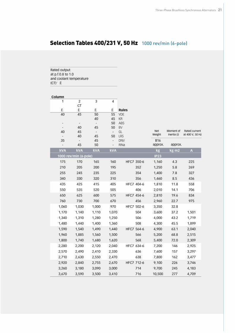
Selection Tables 400/231 V, 50 Hz 1000 rev/min (6-pole)
Three-Phase Brushless Synchronous Alternators 21
Rated output at p.f.0.8 to 1.0and coolant temperature (CT)…℃
Column1 2 3 4
CT℃ ℃ ℃ ℃ Rules40 45 50 55 VDE
40 45 KR- - - 50 ABS- 40 45 50 BV
40 45 - - GL- 40 45 50 LRS
35 - 45 - DNV- 45 50 - RINa
kVA kVA kVA kVA kg kg m2 A
1000 rev/min (6-pole) IP23
175 170 165 160 HFC7 350-6 1,160 4.3 225
210 205 200 195 352 1,250 5.8 269
255 245 235 225 354 1,400 7.8 327
340 330 320 310 356 1,460 8.5 436
435 425 415 405 HFC7 404-6 1,810 11.8 558
550 535 520 505 406 2,010 14.1 706
650 625 600 575 HFC7 454-6 2,810 19.6 834
760 730 700 670 456 2,960 22.7 975
1,060 1,030 1,000 970 HFC7 502-6 3,350 32.8
1,170 1,140 1,110 1,070 504 3,600 37.2 1,501
1,340 1,310 1,280 1,250 506 4,000 43.2 1,719
1,480 1,440 1,400 1,360 508 4,300 45.5 1,899
1,590 1,540 1,490 1,440 HFC7 564-6 4,900 63.1 2,040
1,960 1,885 1,560 1,500 566 5,200 68.8 2,515
1,800 1,740 1,680 1,620 568 5,400 72.0 2,309
2,280 2,200 2,120 2,040 HFC7 634-6 7,200 146 2,925
2,570 2,490 2,410 2,330 636 7,600 157 3,297
2,710 2,630 2,550 2,470 638 7,800 162 3,477
2,920 2,840 2,755 2,670 HFC7 712-6 9,100 226 3,746
3,260 3,180 3,090 3,000 714 9,700 245 4,183
3,670 3,590 3,500 3,410 716 10,500 277 4,709
Net Moment of Rated currentWeight inertia (J) at 400 V, 50 Hz
B16approx. approx.

Selection Tables 400/231 V, 50 Hz 750 rev/min (8-pole)
Rated output at p.f.0.8 to 1.0and coolant temperature (CT)…℃
Column1 2 3 4
CT℃ ℃ ℃ ℃ Rules40 45 50 55 VDE
40 45 KR- - - 50 ABS- 40 45 50 BV
40 45 - - GL- 40 45 50 LRS
35 - 45 - DNV- 45 50 - RINa
kVA kVA kVA kVA kg kg m2 A
750 rev/min (8-pole) IP23
555 530 515 505 HFC7 454-8 3,000 29.0 712
605 570 555 545 456 3,100 32.0 776
720 680 665 650 HFC7 502-8 3,350 39.0 924
850 810 790 670 504 3,600 43.5 1,091
1,040 990 965 940 506 3,800 47.9 1,333
1,145 1,090 1,065 1,040 508 4,100 52.5 1,471
1,305 1,245 1,205 1,175 HFC7 564-8 5,060 92.0 1,674
1,390 1,330 1,285 1,250 566 5,244 96.2 1,783
1,530 1,485 1,440 1,405 568 5,428 102.0 1,963
1,610 1,565 1,515 1,465 HFC7 634-8 6,528 144.0 2,066
1,980 1,920 1,860 1,805 636 6,720 166.0 2,540
2,050 1,985 1,925 1,860 638 7,008 180.0 2,630
3,690 3,575 3,470 3,355 HFC7 712-8 9,200 241.0 4,734
4,255 4,185 4,060 3,925 714 9,500 266.0 5,459
4,895 4,790 4,650 4,500 716 9,900 300.0 6,280
3,710 3,590 3,485 3,375 HFC7 802-8 12,100 440.0 4,760
4,275 4,205 4,080 3,945 804 13,100 510.0 5,485
4,915 4,815 4,670 4,520 806 14,500 585.0 6,306
Net Moment of Rated currentWeight inertia (J) at 400 V, 50 Hz
B16approx. approx.
22
Three-Phase B
rushless Synchronous Alternators

Selection Tables 400/231 V, 50 Hz 600 rev/min (10-pole)
Rated output at p.f.0.8 to 1.0and coolant temperature (CT)…℃
Column1 2 3 4
CT℃ ℃ ℃ ℃ Rules40 45 50 55 VDE
40 45 KR- - - 50 ABS- 40 45 50 BV
40 45 - - GL- 40 45 50 LRS
35 - 45 - DNV- 45 50 - RINa
kVA kVA kVA kVA kg kg m2 A
600 rev/min (10-pole) IP23
510 550 485 475 HFC7 500-10 3,740 39.6 654
605 590 575 555 502 3,800 44.3 776
770 750 730 705 504 3,900 52.0 988
810 790 770 745 506 4,100 58.8 1,039
1,035 1,005 980 950 508 4,300 66.0 1,328
1,165 1,100 1,080 1,045 HFC7 564-10 5,500 102.2 1,495
1,340 1,270 1,245 1,205 566 5,700 106.9 1,719
1,475 1,395 1,370 1,325 568 5,900 114.2 1,892
1,505 1,460 1,415 1,370 HFC7 632-10 6,300 158.2 1,931
1,620 1,575 1,525 1,475 634 6,800 176.4 2,078
1,775 1,720 1,665 1,610 636 7,000 184.1 2,277
1,860 1,805 1,750 1,690 638 7,300 197.2 2,386
2,325 2,250 2,185 2,120 HFC7 710-10 8,600 274.4 2,983
2,465 2,385 2,315 2,245 712 9,300 304.4 3,163
2,645 2,565 2,490 2,415 714 9,700 322.9 3,394
2,840 2,755 2,670 2,590 716 10,100 339.5 3,644
3,160 3,065 2,970 2,880 718 10,900 374.7 4,054
3,240 3,170 3,080 2,995 HFC7 800-10 11,800 456 4,157
3,620 3,540 3,410 3,345 802 13,000 503 4,644
4,205 4,115 3,995 3,885 804 14,200 550 5,395
4,380 4,285 1,465 4,045 806 15,000 596 5,620
Net Moment of Rated currentWeight inertia (J) at 400 V, 50 Hz
B16approx. approx.
Three-Phase Brushless Synchronous Alternators 23

Dimension Tables HFC7 280 to HFC7 406 Type of construction IM B20 Anti-friction bearing
45
9
2
2
1
10
9
86
47
12
11
Type
No.
of
HFC
7Po
les
AA
AA
BA
CA
DA
EA
GA
IA
JA
RB
BBBC
BDC
CAH
HA
280
680
7076
555
028
549
525
026
556
566
523
038
032
875
332
125
20
282
284
498
286
350
750
100
890
700
455
805
415
289
700
960
394
550
480
7838
225
352
354
354
4 or
646
462
053
350
4
356
663
634
400/
402
930
120
1020
780
845
323
780
1040
560
770
731
105
431
613
30
404/
406
178
Shaf
t end
HB
HD
KL
LCLL
LQLR
DD
AD
BD
CD
ED
FD
G⑦D
H⑧
422
520
17.5
1036
421
554
575
65M
2085
E1.6×
0.3
1206
724
660
75
560
735
1813
6361
466
068
590
1455
1560
675
680
810
75M
2090
E1.6×
0.3
1610
1740
835
895
8585
E2.5×
0.4
E2.5×
0.4
635
828
2617
3518
6495
095
010
010
0
940
EEA
FFA
GAGC
105
1869
2079
.5
105
2079
.5
130
130
2222
9090
Uni
t = m
m
Air
inle
t
Air
outle
t
Cen
ter
of g
ravi
ty
Shaf
t end
to D
IN 7
48
Tapp
ed h
ole
DB
to D
IN 3
32
Tapp
ed h
ole
DC
to D
IN 3
32 fr
om H
FC7
354
Relie
f gro
ove
DG
to D
IN 5
09
Relie
f gro
ove
DH
to D
IN 5
09 fr
om H
RC7
354
Gre
asin
g ni
pple
from
HFC
7 35
0
Cov
erin
g fo
r ro
tatin
g re
ctifi
er m
ultic
ore
Cov
er fo
r te
rmin
als
and
exci
tatio
n eq
uipm
ent
Cab
le g
land
for
mul
ticor
e ca
ble
❶ ❷ ❸ ❹ ❺ ❻ ❼ ❽ ❾ ❿
24
Three-Phase B
rushless Synchronous Alternators

Three-Phase Brushless Synchronous Alternators 25
Dimension Tables HFC7 454 to HFC7 806 Type of Construction IM B20 Anti-friction bearing
Cen
ter
of g
ravi
ty
Tapp
ed h
ole
DB
to D
IN 3
32
Cov
er fo
r ro
tatin
g re
ctifi
er
Cov
er fo
r te
rmin
al a
nd e
xcita
tion
equi
pmen
t
Cab
le g
land
hol
der
Air
outle
t
Air
inle
t
❶ ❷ ❸ ❹ ❺ ❻ ❼
5
2
3
1
4
7
6
V WU
H
AD
LA
F
AG
AE
AJ
ARAC
HA
AA
AAI
AB
HFHBHD
PA
P
ØPB
ØK
ØD
DB
BC
CE
BB
BA
LCBD
LQLL
Type
No.
of
HFC
7Po
les
AA
AA
BA
CA
DA
EA
FA
GA
IA
JA
RB
BABB
BCBD
CH
454
4 or
810
6015
012
1091
467
512
2012
2060
444
289
413
0069
090
010
551
550
018
545
5/45
650
24.
..10
1160
180
1380
1013
726
1212
659
482
994
1430
710
1450
725
125
948
200
185
504
4...1
050
64.
..10
508
8...1
016
2281
111
2056
44.
..10
1450
210
1610
1138
915
1470
1504
808
535
1218
1730
1440
1690
720
125
705
230
295
566
4...1
056
84.
..656
88.
..10
1500
1750
750
765
632
4...1
014
6021
016
2012
3091
514
8815
3981
856
812
2818
6214
8517
2574
2.5
120
595
224
295
634
4...1
063
64.
..10
638
4...6
638
8...1
015
6518
0578
2.5
675
710
6...1
015
4016
017
0013
8010
0216
8517
1590
577
614
0320
1617
0019
3085
011
862
224
829
571
26
712
8...1
018
9021
2094
581
271
46
716
6...1
019
6021
9098
088
271
88.
..671
88.
..10
2090
2320
1045
1012
800
8...1
016
2019
018
0014
6011
0018
0018
5093
074
814
4021
0619
4522
0540
088
032
351
080
28.
..10
804
8...1
021
2523
8510
6080
68.
..10
Shaf
t end
HA
HB
HD
HF
KL
LCLL
LQD
DB
EP
PAPB
3080
210
4026
0Ø
2819
1562
580
791
2Ø
110
M24
210
2811
6Ø
120
3085
210
9026
0Ø
2822
5274
510
5010
66Ø
120
M24
220
3212
7Ø
120
2290
827
1104
3011
3514
9225
9Ø
3921
1566
511
4085
5Ø
130
M24
220
3213
7Ø
140
2175
695
915
3011
8414
9232
0Ø
3921
7270
713
2074
4Ø
150
M30
250
3615
8Ø
160
2252
747
834
3512
7015
7638
5Ø
4225
0472
914
9090
5Ø
190
M30
350
4520
0Ø
200
2694
784
1095
2764
819
1165
2894
884
1295
4015
3518
3221
9Ø
4228
5980
514
9012
38Ø
220
M36
350
5023
1Ø
240
840
3012
995
Uni
t = m
m

Dimension Tables HFC7 454 to HFC7 806 Type of Construction IM B20 Sleeve bearing
Cen
ter
of g
ravi
ty
Tapp
ed h
ole
DB
to D
IN 3
32
Cov
er fo
r ro
tatin
g re
ctifi
er
Cov
er fo
r te
rmin
al a
nd e
xcita
tion
equi
pmen
t
Cab
le g
land
hol
der
Air
outle
t
Air
inle
t
❶ ❷ ❸ ❹ ❺ ❻ ❼
2
5
1
3
4
76
V WU
H
AF
AD
AG
AE
AJ
ARAC
HA
AA
AI A AB
HF
ØPB
ØK
ØD
HBHD
PA
DB
BCB
BE
CB
AB
BD LC
LQL
LL
Type
No.
of
HFC
7Po
les
AA
AA
BA
CA
DA
EA
FA
GA
IA
JA
RB
BABB
BCBD
CH
454
4 or
810
6015
012
1091
467
512
2012
2060
444
289
413
0069
090
034
510
551
566
418
545
5/45
650
24.
..10
1160
180
1380
1013
726
1212
659
482
994
1430
710
1450
725
125
948
440
247
504
4...1
050
64.
..10
508
8...1
016
2281
111
2056
44.
..10
1460
210
1620
1226
944
1510
1786
847
568
1228
2044
1440
1690
720
125
705
466
295
566
4...1
056
84.
..656
88.
..10
1500
1750
750
765
632
4...1
014
6021
016
2012
3091
514
8815
3981
856
812
2818
6214
8517
2574
2.5
120
595
470
295
634
4...1
063
64.
..10
638
4...6
638
8...1
015
6518
0578
2.5
675
710
4...1
015
4016
017
0013
8010
0216
8517
1590
577
614
0320
1617
0019
3085
011
862
252
929
571
24.
..671
28.
..10
1890
2120
945
812
714
4...1
071
64.
..10
1960
2190
980
882
718
4...6
718
8...1
020
9023
2010
4510
1280
08.
..10
1620
190
1800
1460
1100
1800
1850
930
748
1440
2106
1945
2205
400
880
589
510
802
8...1
080
48.
..10
2125
2385
1060
806
8...1
0
Shaf
t end
HA
HB
HD
HF
KL
LCLL
LQD
DB
EP
PAPB
3010
4026
026
021
4080
762
580
710
74Ø
110
M24
185
2811
6Ø
110
3085
210
9025
0Ø
2824
7274
564
412
86Ø
120
M24
220
3212
7Ø
120
2510
827
1458
3011
3514
9225
9Ø
3925
2866
511
4010
94Ø
160
M24
220
4016
9Ø
180
2588
695
1151
3011
8414
9232
0Ø
3925
7770
713
2096
0Ø
180
M30
220
4016
9Ø
190
2657
747
1040
3512
7015
7638
5Ø
4229
6372
914
9011
26Ø
200
M30
300
5021
1Ø
215
3153
784
1316
3223
819
1386
3353
884
1516
4015
3518
3221
9Ø
4233
5580
514
9014
62Ø
240
M36
318
5625
2Ø
250
840
3535
995
Uni
t = m
m
26
Three-Phase B
rushless Synchronous Alternators
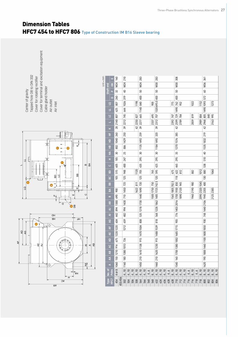
Three-Phase Brushless Synchronous Alternators 27
Dimension Tables HFC7 454 to HFC7 806 Type of Construction IM B16 Sleeve bearing
Cen
ter
of g
ravi
ty
Tapp
ed h
ole
DB
to D
IN 3
32
Cov
er fo
r ro
tatin
g re
ctifi
er
Cov
er fo
r te
rmin
al a
nd e
xcita
tion
equi
pmen
t
Cab
le g
land
hol
der
Air
outle
t
Air
inle
t
❶ ❷ ❸ ❹ ❺ ❻ ❼
5
2
3
1
4
7
6
H
B
DB
P
AF
AD
AG
AE
AJ
AR
AC
HA
AA
AI A AB
HFHB
HD
ØD
ØK
BCB
B
BA
LCBD
LQLL
L
WVU
E C
Type
No.
of
HFC
7Po
les
AA
AA
BA
CA
DA
EA
FA
GA
IA
JA
RB
BABB
BCBD
CH
454
4 or
810
6015
012
1091
467
512
2012
2060
444
289
413
0069
090
010
551
560
518
545
5/45
650
24.
..10
1160
180
1380
1013
726
1212
659
482
994
1430
710
1450
725
125
948
400
247
504
4...1
050
64.
..10
508
8...1
016
2281
111
2056
44.
..10
1450
210
1610
1138
915
1470
1504
808
535
1218
1730
1440
1690
720
125
705
435
295
566
4...1
056
84.
..656
88.
..10
1500
1750
750
765
632
4...1
014
6021
016
2012
3091
514
8815
3981
856
812
2818
6214
8517
2574
2.5
120
595
425
295
634
4...1
063
64.
..10
638
4...6
638
8...1
015
6518
0578
2.5
675
710
4...1
015
4016
017
0013
8010
0216
8517
1590
577
614
0320
1617
0019
3085
011
862
246
529
571
24.
..10
1890
2120
945
812
714
4...1
071
64.
..671
68.
..10
1960
2190
980
882
718
4...6
718
8...1
020
9023
2010
4510
1280
08.
..10
1620
190
1800
1460
1100
1800
1850
930
748
1440
2106
1945
2205
400
130
880
538
510
802
8...1
080
48.
..10
2125
2385
1060
806
8...1
0
Shaf
t end
HA
HB
HD
HF
KL
LCLL
LQD
PD
BE
3080
210
4026
0Ø
2821
4080
762
580
726
032
M24
160
2588
614
2925
0Ø
3922
1274
564
410
2631
940
M24
210
Ø42
2250
827
1198
3011
3514
9225
9Ø
3922
7766
511
4084
040
050
M24
283
2337
695
900
3011
8414
9232
0Ø
3923
1270
713
2069
5.0
400
50M
3028
3
2392
747
775
3512
7015
7638
5Ø
4225
9972
914
9076
240
050
M30
308
2789
784
952
2859
819
1022
2989
884
1152
4015
3518
3221
9Ø
4229
6880
514
9010
9357
260
M36
361
840
3163
995
1273
Uni
t = m
m

Dimension Tables HFJ7 564 to HFJ7 806 Type of Construction IM B20 Anti-friction bearing
Cen
ter
of g
ravi
ty
Tapp
ed h
ole
DB
to D
IN 3
32
Cov
er fo
r ro
tatin
g re
ctifi
er
Cov
er fo
r te
rmin
al a
nd e
xcita
tion
equi
pmen
t
Cab
le g
land
hol
der
❶ ❷ ❸ ❹ ❺
5
2
4
13
UV
W
HDQB
AE AJ
AR
HBAC
A
HA
HF
PA
QC
LQ
BD B
A
ØPBØD
ØK
DB
AF
AD
QA
G
H
AA
AI
AB
P
BC
BB
B
LC
BE
LLL
Type
No.
of
HFJ
7Po
les
AA
AA
BA
CA
DA
EA
FA
GA
IA
JA
RB
BABB
BCBD
BEC
564
4...1
014
5021
016
1011
1393
014
8017
5883
353
512
0019
3314
4016
9072
012
512
0038
523
056
64.
..10
568
4...6
568
8...1
015
0017
5075
012
6063
24.
..10
1460
210
1620
1226
944
1510
1786
847
568
1228
2044
1475
1725
737.
512
512
4038
522
463
44.
..10
636
4...1
063
84.
..663
88.
..10
1556
1805
777.
513
2071
06.
..10
1540
160
1700
1376
1133
1685
2063
1020
776
1403
2355
1700
1930
850
118
1368
392
248
712
671
28.
..10
1890
2120
945
1558
714
671
66.
..10
1960
2190
980
1628
718
8...6
718
8...1
020
9023
2010
4517
5880
08.
..10
1620
190
1800
1460
1226
1800
2257
1112
748
1440
2467
1945
2205
400
130
1630
503
323
802
8...1
080
48.
..10
2125
2385
1810
806
8...1
0
Shaf
t end
HH
AH
BH
DH
FK
LLC
LLLQ
BQ
CD
DB
EP
PAPB
295
3013
0216
7325
939
2115
635
1746
297
828
993.
556
0Ø
130
M24
220
3213
7Ø
140
2175
665
1806
295
3013
5417
2432
0Ø
3921
7265
217
8632
684
210
4656
0Ø
150
M30
250
3615
8Ø
160
2252
692
1866
295
3514
6519
7038
5Ø
4225
0467
419
8645
293
012
1156
0Ø
190
M30
350
4520
0Ø
200
2694
754
2176
2764
789
2246
2894
854
2376
510
4017
4822
4721
9Ø
4228
5980
522
3552
810
3114
7356
0Ø
220
M36
350
5023
1Ø
240
840
3012
995
2415
Uni
t = m
m
28
Three-Phase B
rushless Synchronous Alternators

Three-Phase Brushless Synchronous Alternators 29
Dimension Tables HFJ7 564 to HFJ7 806 Type of Construction IM B16 Sleeve bearing
Cen
ter
of g
ravi
ty
Tapp
ed h
ole
DB
to D
IN 3
32
Cov
er fo
r ro
tatin
g re
ctifi
er
Cov
er fo
r te
rmin
al a
nd e
xcita
tion
equi
pmen
t
Cab
le g
land
hol
der
❶ ❷ ❸ ❹ ❺
5
2
13
4
UV
W
A
HA
B
AF
AD AG
Q
AE
AJ
QC
HD
QB
AR
HBAC
H
AA
AI
AB
HF
ØD
DB
EBC
BB
BA
ØK
LCB
DP
BE
LQLL
L
Type
No.
of
HFJ
7Po
les
AA
AA
BA
CA
DA
EA
FA
GA
IA
JA
RB
BABB
BCBD
BEC
564
4...1
014
5021
016
1011
1393
014
8017
5883
353
512
0019
3314
4016
9072
012
512
0038
543
556
64.
..10
568
4...6
568
8...1
015
0017
5075
012
6063
24.
..10
1460
210
1620
1226
944
1510
1786
847
568
1228
2044
1475
1725
737.
512
512
4038
543
063
44.
..10
636
4...1
063
84.
..663
88.
..10
1556
1805
777.
513
2071
04.
..10
1540
160
1700
1376
1133
1685
2063
1020
776
1403
2355
1700
1930
850
118
1368
392
465
712
4...6
712
8...1
018
9021
2094
515
5871
44.
..10
716
4...6
716
8...1
019
6021
9098
016
2871
84.
..671
88.
..10
2090
2320
1045
1758
800
8...1
016
2019
018
0014
6012
2618
0022
5711
1274
814
4024
6719
4522
0540
013
016
3050
353
880
28.
..10
804
8...1
021
2523
8518
1080
610
Shaf
t end
HH
AH
BH
DH
FK
LLC
LLLQ
BQ
CD
DB
EP
295
3013
0216
7325
9Ø
3922
7763
517
4628
282
899
3.5
560
400
M24
283
50
2337
665
1806
295
3013
5417
2432
0Ø
3923
1265
217
8627
784
210
4656
040
0M
3028
350
2392
692
1866
295
3514
6519
7038
5Ø
4225
9967
419
8631
993
012
1156
040
0M
3030
850
2789
754
2176
2859
789
2246
2989
854
2376
510
4017
4822
4721
9Ø
4229
6877
522
3539
310
3114
7356
057
2M
3636
160
810
3163
965
2415
Uni
t = m
m
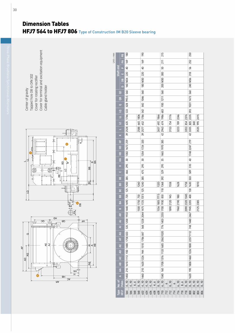
Dimension Tables HFJ7 564 to HFJ7 806 Type of Construction IM B20 Sleeve bearing
Cen
ter
of g
ravi
ty
Tapp
ed h
ole
DB
to D
IN 3
32
Cov
er fo
r ro
tatin
g re
ctifi
er
Cov
er fo
r te
rmin
al a
nd e
xcita
tion
equi
pmen
t
Cab
le g
land
hol
der
❶ ❷ ❸ ❹ ❺
31
4
2
5
UV
W
A
HA
LA
FA
DA
GQ
AE
AJ
AR
HBAC
H
AA
AI
AB
HFQBHD
QC
PA
ØPBØD
DB
BC
BB
BAB
ØK
LCB
D
BE
LLLQ
30
Three-Phase B
rushless Synchronous Alternators
Type
No.
of
HFJ
7Po
les
AA
AA
BA
CA
DA
EA
FA
GA
IA
JA
RB
BABB
BCBD
BEC
564
4...1
014
5021
016
1011
1393
014
8017
5883
353
512
0019
3314
4016
9072
012
512
0038
546
656
64.
..10
568
4...6
568
8...1
015
0017
5075
012
6063
24.
..10
1460
210
1620
1226
944
1510
1786
847
568
1228
2044
1475
1725
737.
512
512
4038
547
563
44.
..10
636
4...1
063
84.
..663
88.
..10
1556
1805
777.
513
2071
06.
..10
1540
160
1700
1376
1133
1685
2063
1020
776
1403
2355
1700
1930
850
118
1368
392
529
712
671
28.
..10
1890
2120
945
1558
714
671
66.
..10
1960
2190
980
1628
718
8...6
718
8...1
020
9023
2010
4517
5880
08.
..10
1620
190
1800
1460
1226
1800
2257
1112
748
1440
2467
1945
2205
400
130
1630
503
589
802
8...1
080
48.
..10
2125
2385
1810
806
8...1
0
Shaf
t end
HH
AH
BH
DH
FK
LLC
LLLQ
BQ
CD
DB
EP
PAPB
295
3013
0216
7325
9Ø
3925
2863
517
4653
382
899
3.5
560Ø
160
M24
220
4016
9Ø
180
2588
665
1806
295
3013
5417
2432
0Ø
3925
7765
217
8654
284
210
4656
0Ø
180
M30
220
4016
9Ø
190
2657
692
1866
295
3514
6519
7038
5Ø
4229
6367
419
8668
393
012
1156
0Ø
200
M30
300
5021
1Ø
215
3153
754
2176
3223
789
2246
3353
854
2376
510
4017
4822
4721
9Ø
4233
3580
522
3539
310
3114
7356
0Ø
240
M36
318
5625
2Ø
250
840
3535
995
2415
Uni
t = m
m

Order Specification of Synchronous Generator
Three-Phase Brushless Synchronous Alternators 31
(1) RATED OUTPUT : _______________________________KVA/kW(2) RATED VOLTAGE : _______________________________V(3) RATED FREQUENCY
□ 50 Hz □ 60Hz(4) NUMBER OF POLES : ____________________________P(5) RATED SPEED : _________________________________RPM(6) RATED POWER FACTOR*□ 0.8 LAGGING□ SPECIAL ___________________________________
(7) PHASE AND WIRES*□ 3 PHASE, 3 WIRES, Y-CONN.□ 3 PHASE, 4 WIRES, Y-CONN.□ SPECIAL __________________________________
(8) INSULATION CLASS / TEMPERATURE RISE*□ F / F □ F / B□ SPECIAL __________________________________
(9) AMBIENT TEMP./ COOLING MEDIUM TEMPERATURE□ 40℃ *□45℃ □50℃ □SPECIAL ℃
(10) ALTITUDE*□ BELOW 1000 METERS ABOVE SEA LEVEL□ SPECIAL __________________________________
(11) OPERATION□ PARALLEL OPERATION□ WITH COMMERCIAL LINE□ WITH THE ONLY IDENTICAL TYPE GENERATOR□ WITH THE ONLY OTHER TYPE GENERATOR
□ ONLY SINGLE OPERATION(12) PRIME MOVER [MAKER : _________ , TYPE : _________ ]
□ DIESEL ENGINE□ TURBINE□ OTHERS
(13) TYPE OF BEARING & Q'TY- Q'TY [□ DOUBLE BEARING
□ SINGLE BEARING- TYPE OF BEARING□ SLEEVE BEARING
# LUBRICATION TYPE [□SELF LUB. , □FORCED LUB.]□ ROLLER BEARING
(14) COUPLING*□ RIGID COUPLING□ FLEXIBLE COUPLING□ SPECIAL __________________________________# NOTE : IN GENERAL, COUPLING BELONGS TO SUPPLY SCOPE
OF THE MANUFACTURER OF PRIME MOVER. IN CASE THATTHE SUPPLIER OF GEN. IS REQUESTED TO SUPPLYCOUPLING,EXTRA COST SHALL BE CHARGED.
(15) ENCLOSURE*□ DRIP-PROOF / IP23
□ AIR FILTER*□ NOT REQUIRED□ REQUIRED
□ TOTALLY-ENCLOSED WATER-AIR-COOLED / IP44□ COOLER TYPE*□ DOUBLE TUBE TYPE□ SPECIAL __________________________________
□ WATER LEAKAGE DETECTOR*□ REQUIRED□ COOLING AIR TEMP. DETECTOR*□ NOT REQUIRED□REQUIRED□PT100 OHM (AT 0℃)□SPECIAL _________________________________
□ SPECIAL _______________________________________
(16) STATOR WINDING TEMP. DETECTOR*□ NOT REQUIRED□ REQUIRED, ___ EA PER PHASE [SPEC : ____________ ]
# NOTE : CONTROLLER AND/OR INDICATOR FOR STATORWINDING TEMP DETECTOR ; EXTRA COST
(17) BEARING TEMP. DETECTOR / ONLY FOR SLEEVE BEARING*□ NOT REQUIRED□ REQUIRED, 1 EA PER BEARING [SPEC : _____________ ]
# NOTE:CONTROLLER AND/OR INDICATOR FOR BEARINGTEMP DETECTOR IS OUT OF SUPPLY SCOPE.
(18) ANTI-CONDENSATION HEATER□ POWER SOURCE
1Ø, □ 110V □ 220V □ SPECIAL(19) DIRECTION OF ROTATION VIEW FROM DRIVE END
□ CLOCK-WISE□ COUNTER CLOCK-WISE
(20) LOCATION OF TERMINAL BOX VIEW FROM DRIVE END□ LEFT HAND SIDE□ RIGHT HAND SIDE□ SPECIAL __________________________________
(21) CABLE ENTRY OPENING□ CABLE GLAND□ DIRECTION OF CABLE GRAND□ CONDUCT SIZE□ SPECIAL __________________________________
(22) PAINT COLOR*□ MUNSELL NO. 7.5 B/G 6/1.5□ SPECIAL __________________________________
(23) SPECIAL LOAD□ UPS□ RECTIFIER□ SPECIAL
(24) SPARE PART□ NOT REQUIRED□ REQUIRED, SPECIFY ITEMS AND QUANTITY__________________________________________________________________________________________
(25) TEST AND INSPECTION□ HHI STANDARD□ OWNER'S INSPECTION□ PUBLIC INSTITUDE INSPECTION□ SPECIAL __________________________________
(26) SPECIAL REQUIREMENT, PLEASE SPECIFY______________________________________________________________________________________________________________________________________________________________________________________________________________________________________________________________________________# NOTE : MARKED * IS HHI STANDARD
CUSTOMER : ________________________________________
PROJ. NAME/SHIP NO. : _______________________________
STANDARD / CLASS : ___________________________________
CUSTOMER CHARGER / TEL. : __________________________
OUR REF. NO. : _______________________________________
DELIVERY : ____________________________________________
QUANTITY : ____________________________________________
SALES MAN : ____________________________________________