we manufacture solution - eatonpub/@eaton/@hyd/documents/content/... · hydraulics we manufacture h...
TRANSCRIPT

Hyd
raulics
We Manufacture
SolutionsS o l u t i o n s
H
y
d
r
a
u
l
i
c
s
h
y
d
r
a
u
l
i
c
s
KBD/TG4V-3, 1* SeriesPressures to 350 bar (5000 psi)
Vickers TM
Proportional Directional Valves without Feedback
This product has been designed and tested to meet specic standardsoutlined in the European Electromagnetic Compatibility Directive(EMC) 89/336/EEC, amended by 91/263/EEC, 92/31/EEC and 93/68/EEC,article 5. For instructions on installation requirements to achieve eective
protection levels, see this leaet and the Installation Wiring Practices for VickersTM ElectronicProducts leaet 2468. Wiring practices relevant to this Directive are indicated by Electromagnetic Compatibility (EMC).

Proportional Directional Valves without Feedback
2
Contents
General Description Page 3
Typical Section Page 3
Model Codes Page 4
Spool Data Page 5
Functional Symbols Page 5
Operating Data Page 6
Power Capacity Envelopes Page 8
Flow Characteristics Page 11
Frequency Response Page 14
Installation Dimensions
KBDG4V-3 Page 15
KBTG4V-3 Page 15
Parallel Flow Path Module Page 16
Subplates and Mounting Surfaces Page 16
Single Station Subplates Page 17
Port Threads Page 17
Mounting Surface Interface to ISO 4401 (Size 03) Page 17
Electrical Information
Block Diagram Page 18
Typical Connection Arrangements Page 19
Application Data Page 20

3
Proportional Directional Valves without Feedback
VickersTM KB*G4V-3 proportional valves are designedto provide controlled oil flow in proportion to anelectrical command signal. They are available in twoversions. Firstly a double solenoid version that willprovide reversible flow and return to an actuator.Secondly a single solenoid version that provides asingle direction of flow.The KB* valve incorporates an integral controlamplifier. Factory set adjustments for gain, spooldeadband compensation and dither ensureexcellent reproducibility valve-to-valve.
Electrical connection is via a standard 7-pin plugand requires a power supply and command signalwhich can be either voltage or current (model codeoption).
In addition to improving machine performance andlife, the KB* proportional valves substantiallysimplify system design by combining direction andflow capabilities in one single package that mountsonto a standard ISO 4401 interface.
General Description
New Features and Benefits
• State of the art digital electronic technology• Rugged and robust die-cast housing• Optional voltage (+/-10 volt) or
current (4-20 mA) demand input• Adjustable ramp (0-12 sec)• Wide range of supply voltage• Optional external enable feature• IP67 environmental protection• Full CE electromagnetic capability to
EN 50081-2 and EN 50082-2• Vibration and shock tested
Standard Features and Benefits
• Factory adjusted to ensure excellent valve-to-valve reproducibility
• Installation wiring reduced and simplified• Wide range of spool and flow rate options• Simple valve removal and replacement for
service i.e. plug and play• Standard 7-pin connector• 350 bar (5000 psi) pressure rating• Supported by auxiliary function electronic
modules
Typical Section
KB*G4V-3-P*7, 1* Series

Proportional Directional Valves without Feedback
4
10 Spool Metering Type
N - Meter-in and meter-out
F - Fine meter-in and meter-out
S - Meter-out only
11 Flow Rating for Asymmetric Flow Spools
10 - 10 L/min (2.64 USgpm) (20N10 only)- Omit for symmetrical spools
12 Manual Overrides
Blank - Plain overrides
H - Water resistant overrides
Z - No overrides
13 Solenoid Energization Identity
V - Solenoid “A” is at “A” port end,solenoid “B” is at “B” port end,independent of spool type
Blank - US ANSI B93.9 standard(energize solenoid “A”, flow is P-A)
14 Electrical Command Option
1 - +/- 10V control signal
2 - 4-20 mA control signal
15 Electrical Connection
PC7 - 7-pin connector, without plug supplied
PE7 - 7-pin connector, with plugsupplied
PH7 - As PE7 but with pin “C” used forenable signal
PR7 - As PC7 but with pin “C” used forenable signal
16 Coil Rating
H - 24V DC amplifer supply
1 Valve Type
KB - Proportional valve with integralamplifier, B series
2 Control Type
D - Directional valve
T - Throttle valve
3 Mounting
G - Subplate mounted
4 Operation
4 - Solenoid operated
5 Pressure Rating
V - 350 bar (5000 psi), ports P, A & B
6 Interface
3 - ISO 4401, size 03-02-0-94,ANSI B93.7M-DO3
7 Spool Type
2 - Closed center33 - P port closed, A & B to tank
8 Spool/Spring Arrangement
C - Spring centered, dual solenoid
B - Spring centered, single solenoid(solenoid “B” version only,solenoid “A” for “V” version)
9 Spool Flow Rating - at 5 bar (75 psi) per metering flow path
03 - 3 L/min (0.79 USgpm)
07 - 7 L/min (1.85 USgpm)
13 - 13 L/min (3.43 USgpm)
20 - 20 L/min (5.28 USgpm)
24 - 24 L/min (6.34 USgpm)
17 T port Pressure
7 - 210 bar (3000 psi)
18 Design Number
1* series - Subject to change
Model Codes
KB * G 4 V 3 ** * ** * ** * (V) M * P*7 H 7 10
3 542
Warning
Valves with integral amplifiers are suppliedwith or without the metal 7-pin plug. The VickersTM
plug, part no. 934939, must be correctly fitted toensure that the EMC rating and IP67 rating areachieved. The plug retaining nut must be tightenedwith a torque of 2-2,5 Nm (1.5-2.0 lbf ft) to effect aproper seal.
1 6 7 8 9 10 11 12 13 14 15 16 1817
5
Proportional Directional Valves without Feedback
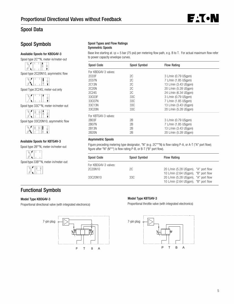
Spool Data
T B APP T B A
Model Type KBDG4V-3
Proportional directional valve (with integrated electronics)
Spool Types and Flow RatingsSymmetric Spools
Base line starting at p = 5 bar (75 psi) per metering flow path, e.g. B to T. For actual maximum flow referto power capacity envelope curves.
Spool Symbols
Available Spools for KBDG4V-3
Spool type 2C**N, meter-in/meter-out
Spool type 2C20N10, asymmetric flow
Spool Type 2C24S, meter-out only
Spool type 33C**N, meter-in/meter-out
Spool type 33C20N10, asymmetric flow
Available Spools for KBTG4V-3
Spool type 2B**N, meter-in/meter-out
edoCloopS lobmySloopS gnitaRwolF
:sevlav3-V4GDBKroFF30C2N70C2N31C2N02C2S42C2F30C33N70C33N31C33N02C33
C2C2C2C2C2C33C33C33C33
)mpgSU97.0(nim/L3)mpgSU58.1(nim/L7)mpgSU34.3(nim/L31)mpgSU82.5(nim/L02)mpgSU43.6(nim/L42
)mpgSU97.0(nim/L3)mpgSU58.1(nim/L7)mpgSU34.3(nim/L31)mpgSU82.5(nim/L02
:sevlav3-V4GTBKroFF30B2N70B2N31B2N02B2
B2B2B2B2
)mpgSU97.0(nim/L3)mpgSU58.1(nim/L7)mpgSU34.3(nim/L31)mpgSU82.5(nim/L02
Asymmetric Spools
Figure preceding metering type designator, "N" (e.g. 2C***N) is flow rating P-A, or A-T ("A" port flow);figure after "N" (N***) is flow rating P-B, or B-T ("B" port flow).
edoCloopS lobmySloopS gnitaRwolF
:sevlav3-V4GDBKroF01N02C2
01N02C33
C2
C33
wolftrop"A",)mpgSU82.5(nim/L02wolftrop"B",)mpgSU46.2(nim/L01wolftrop"A",)mpgSU82.5(nim/L02wolftrop"B",)mpgSU46.2(nim/L01
Functional SymbolsModel Type KBTG4V-3
Proportional throttle valve (with integrated electronics)
7-pin plug 7-pin plug
Spool type 33B**N, meter-in/meter-out

Proportional Directional Valves without Feedback
6
D
CE
F B
GA
Operating Data
View of pins of fixed half
7-pin plug connector
.)F°221(C°05dna)SUS861(tSc63tadiulfhtiwlacipytsiataD.reifilpmalargetnihtiwsevlaV3-V4GT/DBK
ylppusrewoP)H61edocledoM()V42(
)elppirkaep-ot-kaep%01gnidulcniV63otV12(CDV42A2.1-tnerrucxam
)stloV(langisdnammoCecnadepmitupnI
)141edocledoM(BnipotegatlovedomnommoC
CDV01+otV01-ro,CDV01-ot0ro,CDV01+ot0k74 Ω
V4
)tnerruC(langisdnammoC)241edocledoM(ecnadepmitupnI
Am02ot4001 Ω
langiselbaneevlaVelbanEelbasiD
ecnadepmitupnI
)xamV63(V0.9>V0.2<
k63 Ω
niP
ABCDEFG
noitpircseD
)+(evitisopylppusrewoPnruterdnammoctnerrucdnaV0ylppusrewoP
)7RP&7HP(elbaneevlaV)nitnerrucroV+(langisdnammoC
)DNGtnerrucroV-(langisdnammoCrotinomtuptuO
dnuorgevitcetorP
:)CME(ytilibitapmoccitengamortcelE)m/V01(noissimE)m/V01(ytinummI
2-18005NE2-28005NE
sevlavDBK)Fnip(langisrotinoMecnadepmituptuO
)ylppusrewopV42A/V93.0(V5+ot0k01 Ω
T-B-A-PhguorhtwolfhtiwesnopsertupnipetS∆ A-P.g.e,htapgniretemrep)isp57(rab5=p
:noisrev)H(V42rofpetswolfderiuqeR%001-00-%001
%09-ot%09+
:petsderiuqerfo%09hcaerotemiTsm62sm53sm04
:)sgnittesyrotcafta(evlav-ot-evlav,ytilibicudorpeRlangisdnammoc%001tawolF ≤ %5
:noitcetorPlacirtcelE
latnemnorivnEdetcetorpytiralopesreveR
76PIssalC,925CEI
ecnamrofrepllufrofegnarerutarepmetriatneibmAecnamrofrepllufrofegnarerutarepmetliO
)F°851otF°23(C°07otC°0)F°851otF°23(C°07otC°0
ecnamrofrepdecudertakrowlliwsevlavhcihwtaerutarepmetmuminiM )F°4-(C°02-
egnarerutarepmetegarotS )F°581+otF°31-(C°58+otC°52-
:stcudorpgnitroppuS:)gnitnuomliar-NID(seludomcinortceleyrailixuA
retrevnoclangiS*2A-102-NOC-AHErotareneglangisdnammoC*1-A-102-GSD-DHE
rotarenegpmaR*2-A-102-PMR-AHErellortnocDIP*2-A-102-DIP-AHEylppusrewoP01-A-102-USP-AHE
A0142golataceeS0742golataceeSA0142golataceeS
7242golataceeSA0142golataceeS
7
Proportional Directional Valves without Feedback
Operating Data (cont.)
emitpmaR )%001-0(tupnipetsllufrofces21-0
rotcafytudevitaleR )%001=DE(gnitarsuounitnoC
T-B-A-PhguorhtwolfhtiwsiseretsyH wolfdetarfo%8<
3-V4GDBK:ssaM3-V4GTBK
.xorppa)bl9.5(gk7,2
.xorppa)bl2.4(gk9,1

Proportional Directional Valves without Feedback
8
0
5
10
15
20
25
30
0 50 100
150
200
250
0
5
10
15
20
25
30
35
0 50 100
150
200
250
Power Capacity EnvelopesFl
ow
USgpm
Pressure drop
Power Capacity Looped FlowL/min
bar
psi
Flow
USgpm Power Capacity Looped Flow
Pressure drop
L/min
psi
bar
2*24S
2*20N
2*13N
2*07N
2*03F
33*20N
33*13N
33*07N
33*03F
0
500
1000
3000
3500
2000
1500
2500
0
500
1000
3000
3500
2000
1500
2500
8
6
4
2
0
8
6
4
2
0
BB AA
T PP
or
T
BB AA
T PP
or
T
9
Proportional Directional Valves without Feedback
0
5
10
15
20
25
300 50 100
150
200
250
0
5
10
15
20
25
30
35
0 50 100
150
200
250
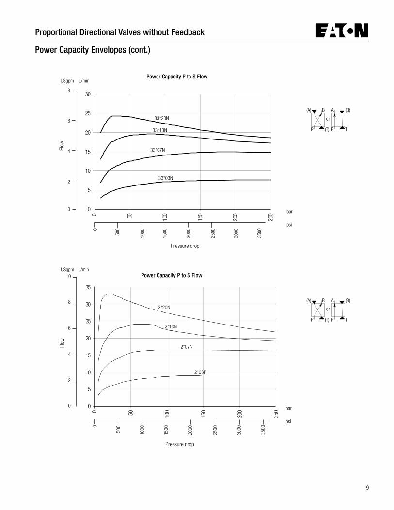
Power Capacity Envelopes (cont.)
Power Capacity P to S Flow
Pressure drop
psi
bar
L/min
Flow
USgpm
psi
bar
Power Capacity P to S Flow
Pressure drop
33*03N
33*07N
L/min
Flow
USgpm
2*07N
2*03F
2*13N
2*20N
33*20N
33*13N
(B)
T
(A) B A
P (T) P
or
(B)
T
(A) B A
P (T) P
or
8
6
4
2
0
0
500
1000
3000
3500
2000
1500
2500
8
6
4
2
0
10
0
500
1000
3000
3500
2000
1500
2500

Proportional Directional Valves without Feedback
10
0
5
10
15
20
25
300 50 100
150
200
250
Power Capacity Envelopes (cont.)
Total pressure drop
Power capacity *C20N10 (for various area ratios)
4:1 Extending 2:1 Extending
2:1 Retracting1.5:1 Retracting
L/min
bar
psi
Inle
t flo
w
USgpm
1.5:1 Extending
4:1 Retracting
8
6
4
2
0
0
500
1000
3000
3500
2000
1500
2500
11
Proportional Directional Valves without Feedback
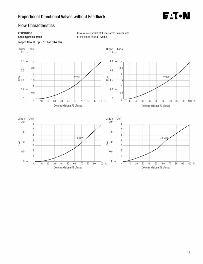
Flow Characteristics
Looped flow at p = 10 bar (144 psi)
KB valves are preset at the factory to compensatefor the effect of spool overlap.
USgpm L/min
3
2.5
2
1.5
1
0.5
0
Flow
40 6050 70 80 90 100302010
33*03F
1.0
0.8
0.6
0.4
0.2
0
Command signal % of max.
L/minUSgpm
Flow
40 6050 70 80 90 100302010
3
2.5
2
1.5
1
0.5
0
2*03F
USgpm L/min
6
5
4
3
2
1
0
7
40 6050 70 80 90 100302010
Flow
2*07N
2.0
1.5
1.0
0.5
0
L/min
6
5
4
3
2
1
0
7
40 6050 70 80 90 100302010
Flow
33*07N
USgpm2.0
1.5
1.0
0.5
0
KBD/TG4V-3Spool types as noted
% %
Command signal % of max.Command signal % of max.
Command signal % of max.
% %
1.0
0.8
0.6
0.4
0.2
0

Proportional Directional Valves without Feedback
12
L/minUSgpm
Flow
40 6050 70 80 90 100302010
20
15
10
0
5
2*20N
Flow Characteristics (cont.)
Looped flowpath at p = 10 bar (144 psi)
USgpm L/min
Flow
90 100
20
15
10
0
5
33*20N
L/minUSgpm
Flow
40 6050 70 80 90 100302010
14
12
10
8
6
4
0
2
2*13N
0
3
2
1
USgpm L/min
Flow
14
12
10
8
6
4
0
2
33*13N
40 6050 70 80 90 100302010
0
4
1
2
5
3
KBD/TG4V-3Spool types as noted
KB valves are preset at the factory to compensatefor the effect of spool overlap.
Command signal % of max.
%
Command signal % of max.
%
Command signal % of max.
%
Command signal % of max.
% 40 6050 70 80302010
0
3
2
1
0
4
1
2
5
3

13
Proportional Directional Valves without Feedback
Flow Characteristics (cont.)
Looped flowpath at p = 10 bar (144 psi)
L/minUSgpm
USgpm L/minL/minUSgpm
Flow
Flow
Flow
20
15
10
0
5
25
20
15
10
0
5
20
15
10
0
5
2C24S
2C20N10 P to AP to AP to AP to AP to A
33C20N10 P to BP to BP to BP to BP to B
33C20N10 P to AP to AP to AP to AP to A
KB valves are preset at the factory to compensatefor the effect of spool overlap.
40 6050 70 80 90 1003020100
4
1
2
5
3
40 6050 70 80 90 100302010
2C020N10 P to A2C20N10 P to BP to BP to BP to BP to B
40 6050 70 80 90 1003020100
4
1
2
5
3
0
4
1
2
5
3
KBD/TG4V-3Spool types as noted
Command signal % of max.
%
Command signal % of max.
%
Command signal % of max.
%
6
7

Proportional Directional Valves without Feedback
14
Frequency Response (Typical)
For an amplitude of ±25% max. stroke about the50% position, at p (P-B) = 5 bar (75 psi)
Ampl
itude
rat
io (
dB)
Frequency (Hz)
0.1 1 10 100
2
0
-2
-4
-6
-8
-10
0.2 0.3 0.5 2 3 4 5
Frequency (Hz)
Phas
e la
g (d
egre
es)
150
100
50
0
Frequency (Hz)
0.1 1 10 1000.2 0.3 0.5 2 3 4 5
15
Proportional Directional Valves without Feedback
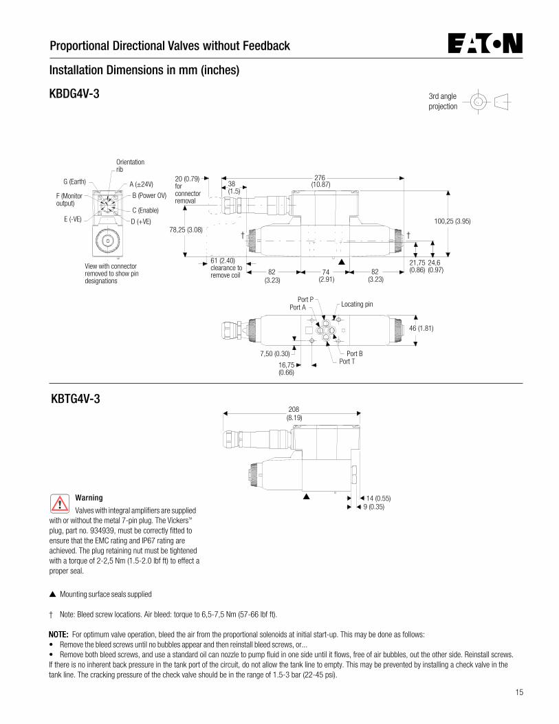
Orientationrib
View with connectorremoved to show pindesignations
20 (0.79)forconnectorremoval
61 (2.40)clearance toremove coil
G (Earth)
F (Monitoroutput)
E (-VE)C (Enable)
D (+VE)
A (±24V)
B (Power OV)
Locating pin
Port BPort T
Port PPort A
100,2578,25 (3.08)
82 8221,75(0.86)
24,6(0.97)74
38(1.5)
16,75(0.66)
7,50 (0.30)
46 (1.81)
276
208
14 (0.55)9 (0.35)
Installation Dimensions in mm (inches)
3rd angleprojection
KBDG4V-3
Mounting surface seals supplied
† Note: Bleed screw locations. Air bleed: torque to 6,5-7,5 Nm (57-66 lbf ft).
NOTE:NOTE:NOTE:NOTE:NOTE: For optimum valve operation, bleed the air from the proportional solenoids at initial start-up. This may be done as follows:• Remove the bleed screws until no bubbles appear and then reinstall bleed screws, or...• Remove both bleed screws, and use a standard oil can nozzle to pump fluid in one side until it flows, free of air bubbles, out the other side. Reinstall screws.If there is no inherent back pressure in the tank port of the circuit, do not allow the tank line to empty. This may be prevented by installing a check valve in thetank line. The cracking pressure of the check valve should be in the range of 1.5-3 bar (22-45 psi).
KBTG4V-3
Warning
Valves with integral amplifiers are suppliedwith or without the metal 7-pin plug. The VickersTM
plug, part no. 934939, must be correctly fitted toensure that the EMC rating and IP67 rating areachieved. The plug retaining nut must be tightenedwith a torque of 2-2,5 Nm (1.5-2.0 lbf ft) to effect aproper seal.
(10.87)
(3.23) (2.91) (3.23)
(3.95)
(8.19)
† †

Proportional Directional Valves without Feedback
16
P
T
A
B
Parallel Flow Path Module
50,0(1.97)
65,0(2.6)
47,6(1.9)
Nameplate
20,0 (0.78)
4 holes Ø 5,6 (0.22 dia),counterbored to Ø 9,5 (0.374 dia)P T B A
P T B A
Size 03 Parallel-Flow-Path ModuleKDGMA-3-616265-1*
Typically used for doubling effective flow capabilityof single solenoid proportional valves (throttlevalves).
A, TA and T
B ports at subplate face
are blind holes fitted with O-seals.
General Description
If a subplate is not used a machined pad must beprovided for valve mounting. Pad must be flatwithin 0,0127 mm (.0005 inch) and smooth within1,6 µm (63 microinch). Mounting bolts, whenprovided by customer, should be ISO 898 class12.9 or better.
Dimensional Tolerances
Dimensional tolerance on interface drawings is±0,2 mm (±0.008") except where otherwisestated. ISO 4401 specifies inch conversion to±0.01".
Conversion from Metric
ISO 4401 gives dimensions in mm. Inchconversions are accurate to 0.01" unlessotherwise stated.
Mounting Bolt Tappings
ISO 4401 gives metric thread tappings. AlternateUNC tappings are recommendations that allowthese plates and associated valves to be used up totheir maximum pressures, when using recom-mended VickersTM bolt kits, or bolts of an equivalentstrength. It is recommended that customers’ ownmanifold blocks for UNC bolts should be tapped tothe minimum depths given in the footnotes.
Subplates and Mounting Surfaces
P AT B
dnanoitpircseD)bl(gkssaM
lobmySlanoitcnuF edoCledoM erusserP.xaM
;etalpbusnoitats-elgniSB,A,T,PstropraeR
)9.2(3,1noritsaC
R-*1-3-MVGDK*1-308676-3-MVGDK
)stropFNU/EAS(
)isp0063(rab052
Subplates
* Design number subject to change. No change of installation dimensions for design numbers10 to 19 or 21 to 29 inclusive.“S" suffix = SAE/UNC ports and/or UNC fixing bolt tappings and/or orifice plugs as appropriate.“R" suffix = BSPF and/or metric fixing bolt tappings and/or orifice plugs as appropriate.
Installation Dimensions in mm (inches)

17
Proportional Directional Valves without Feedback
L
A
B
PT A
B
P T
P AT B
L
AB
P
T
sdaerhTtroP
ledoM B,A,T,PstroP LtroP
5M/stropFPSB:stlobgnitnuom
R-*1-3-MVGDK raeR G3/8 (" 3/8 peed)74.0(0,21x)FPSB" G1/8 (" 1/8 peed)74.0(0,21x)FPSB"
CNU42-01#/stropEAS:stlobgnitnuom
*1-308676-3-MVGDK raeR 3/4 )EAS(peed)65.0(3,41xB2-FNU61-" 7/ 61 )EAS(peed)64.0(6,11xB2-FNU02-"
Mounting Surface to ISO 4401 (Size 03)This interface conforms to:ISO 4401-03-02-0-94plus location pin holeANSI/B93.7M (and NFPA) size 03CETOP R35H4.2-4-03, plus locationpin holeDIN 24340 Form A6 plus locationpin hole
4 ports Ø 6,3 (0.25 dia).For all VickersTM size 03valves this diameter maybe increased toØ 7,5 (0.29)
4 holes, M5 x 12 (0.47)min. full thread depth
5,1 (0.20)12,7(0.5)
21,5 (0.85)
30,2 (1.18)
0,75 ± 0,1(0.03 ± 0.004)
48(1.89)min.
7,5 (0.29)
Ø 4,0 x 4,3 min. depth(0.16 dia x 0.17) forlocating pin
31,0 ± 0,1(1.22 ± 0.004)
25,9 (1.01)15,5 (0.61)
70 (2.75) min.
31,75 ± 0,1(1.25 ± 0.004)
40,5 ± 0,1(1.59 ± 0.004)
#10-24 UNC-2B optional.
4 holes Ø 5,6(0.22 dia)spotfaced toØ 13,0 (0.51 dia)
4 holes tapped according to model type (see table):For models with BSPF ports, M5 x 12 (0.47) deepFor models with SAE ports, #10-24 UNC-2B x 12,7 (0.5) deep
4 system connections forrear-entry models, see table
Rearmountingface
Port L 16,3(0.64)59,25 (2.33)
36,0 (1.42)12,75 (0.5)
12,75 (0.5)
57,25(2.25)
35,0(1.38)
20,0 (0.79)84,0 (3.3)
72,0 (2.83)
15,75(0.62)
72,0(2.83)
19,75(0.78)
6,0(0.24)
6,0 (0.24)
35,0(1.38)
Installation Dimensions in mm (inches)
Single-Station Subplates
84,0(3.3)
11,5 (0.45) from rear mounting face to port centerline.
Proportional Directional Valves without Feedback
18
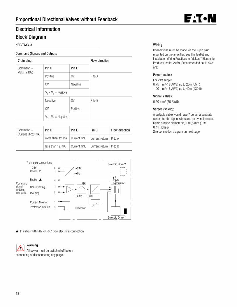
Electrical InformationBlock DiagramKBD/TG4V-3
Command Signals and Outputs
Wiring
Connections must be made via the 7-pin plugmounted on the amplifier. See this leaflet andInstallation Wiring Practices for VickersTM ElectronicProducts leaflet 2468. Recommended cable sizesare:
Power cables:
For 24V supply:0,75 mm2 (18 AWG) up to 20m (65 ft)1,00 mm2 (16 AWG) up to 40m (130 ft)
Signal cables:
0,50 mm2 (20 AWG)
Screen (shield):
A suitable cable would have 7 cores, a separatescreen for the signal wires and an overall screen.Cable outside diameter 8,0-10,5 mm (0.31-0.41 inches)See connection diagram on next page.
In valves with PH7 or PR7 type electrical connection.
Solenoid Drive 2
Commandsignalvoltage,see table
Ramp
7-pin plug connections
Warning
All power must be switched off beforeconnecting or disconnecting any plugs.
Deadband
+5V
+24V
Gain
Protective Ground
Non-inverting
Inverting
Enable
Power 0V+24V
Current Monitor
AB
G
C
F
E
D
PWMModulator
Solenoid Drive 1
gulpnip-7 noitceridwolF
=dnammoC)V01±(stloV
DniP EniP
evitisoP VO AotP
VO evitageN
VD
V-E
evitisoP=
evitageN VO BotP
VO evitisoP
VD
V-E
evitageN=
=dnammoC)Am02-4(tnerruC
DniP EniP BniP noitceridwolF
Am21nahterom DNGtnerruC nrutertnerruC AotP
Am21nahtssel DNGtnerruC nrutertnerruC BotP

19
Proportional Directional Valves without Feedback
Outer Screen
Inner Screen
Drain Wire
C
A
D or E
B
F
G
KB...PC7/PE7 valveUser Panel
PowerSupply
DemandSignal
SolenoidCurrentMonitor
Connectorshell
0V must beconnected to ground
Input
0V
0V+/-10V
+24V0V
Wiring Connections
Wiring Connections for Valves with “Enable” Feature
Note:In applications where the valve must conform toEuropean RFI/EMC regulations, the outer screen(shield) must be connected to the outer shell of the7-pin connector, and the valve body must befastened to the earth ground. Proper earthgrounding practices must be observed in this case,as any differences in command source and valveground potentials will result in a screen (shield)ground loop.
Warning
Electromagnetic Compatibility (EMC)It is necessary to ensure that the valve is wired up as above. For effective protection the user electrical cabinet, the valve subplate or manifold and
the cable screens should be connected to efficient ground points. The metal 7-pin connector part no. 934939 should be used for the integral amplifier.In all cases both valve and cable should be kept as far away as possible from any sources of electromagnetic radiation such as cables carrying heavy current,relays and certain kinds of portable radio transmitters, etc. Difficult environments could mean that extra screening may be necessary to avoid the interference.It is important to connect the 0V lines as shown above. The multi-core cable should have at least two screens to separate the demand signal and monitor outputfrom the power lines.The enable line to pin C should be outside the screen which contains the demand signal cables.
Typical Connection Arrangements
Valve must beconnected toground viasubplate
Valve must beconnected toground viasubplate
KB...PR7/PH7 valveOuter Screen
Inner Screen
Drain Wire
E or D
F
D or E
C
BA
G
PowerSupply
EnableSignal
DemandSignal
SolenoidCurrentMonitor
User Panel
0V must beconnected to ground
Connectorshell
+24V0V
0V+8.5Vto 36V
0VInput
Enclosure
Pin C may beconnected to ground orleft unconnected.

Proportional Directional Valves without Feedback
20
Fluid CleanlinessProper fluid condition is essential for long andsatisfactory life of hydraulic components andsystems. Hydraulic fluid must have the correctbalance of cleanliness, materials and additives forprotection against wear of components, elevatedviscosity and inclusion of air.
Recommendations on contamination controlmethods and the selection of products to controlfluid condition are included in publication 9132 or561, “Guide to Systemic Contamination Control”.The book also includes information on the conceptof “ProActive Maintenance”. The followingrecommendations are based on ISO cleanlinesslevels at 2 µm, 5 µm and 15 µm.
For products in this catalog the recommendedlevels are:0 to 70 bar (1000 psi)............................18/16/1370 + bar (1000 + psi)............................17/15/12
VickersTM products, as any components, will operatewith apparent satisfaction in fluids with highercleanliness codes than those described. Othermanufacturers will often recommend levels abovethose specified.
Experience has shown, however, that life of anyhydraulic components is shortened in fluids withhigher cleanliness codes than those listed above.These codes have been proven to provide a longtrouble-free service life for the products shown,regardless of the manufacturer.
Hydraulic FluidsMaterials and seals used in these valves arecompatible with antiwear hydraulic oils, and withnon-alkyl-based phosphate esters.
The extreme operating viscosity range is 500 to13 cSt (2270 to 70 SUS) but the recommendedrunning range is 54 to 13 cSt (245 to 70 SUS).
InstallationThe proportional valves in this catalog can bemounted in any attitude, but it may be necessary incertain demanding applications, to ensure that thesolenoids are kept full of hydraulic fluid. Goodinstallation practice dictates that the tank port andany drain port are piped so as to keep the valvesfull of fluid once the system start-up has beencompleted.
Mounting Bolt KitsBK02-156493M (metric)BK590716 (inch)If not using recommended VickersTM bolt kits, boltsused should be to ISO 898, 12.9 or better.
Seal Kit02-351111
Plugs7-pin plug (metal) .................................... 9349397-pin plug (plastic) .................................. 694534(Metal plug must be used for full EMC protection)
Note:Note:Note:Note:Note: An alternative metal connector which givesEMC protection but not IP67 rating is available fromITT-Cannon, part number CA06-COM-E-14S-A7-P.
Service InformationThe products from this range are preset at thefactory for optimum performance; disassemblingcritical items would destroy these settings. It isrecommended that if any mechanical or electronicrepair is necessary, valves should be returned tothe nearest Eaton Hydraulics repair center. Theproducts will be refurbished as necessary andretested to specification before return.
Field repair is restricted to the replacement of theseals.
Application Data

21
Proportional Directional Valves without Feedback

© 2009 Eaton CorporationAll Rights ReservedPrinted in USADocument No. V-VLDI-MC014-ESupersedes 11-05-5071 EN 10-01March 2009
EatonFluid Power GroupHydraulics Group USA14615 Lone Oak RoadEden Prairie, MN 55344USATel: 952-937-9800Fax: 952-294-7722www.eaton.com/hydraulics
EatonFluid Power GroupHydraulics Group EuropeRoute de la Longeraie 71110 MorgesSwitzerlandTel: +41 (0) 21 811 4600Fax: +41 (0) 21 811 4601
EatonFluid Power GroupHydraulics Group Asia Pacific 11th Floor Hong Kong New World Tower 300 Huaihai Zhong Road Shanghai 200021 China Tel: 86-21-6387-9988 Fax: 86-21-6335-3912