we produce only spur gear€¦ · gear hobbing machine klingelnberg gmbh p 6 gear measuring center...
TRANSCRIPT

A Main machining and verification equipment ..... 3
D Selecting .................... 17
E Terminology ........ 19
B.1 FRAMEs/STAGEs/RATIOs.................................. 5B.2 Ordering info ............................................ 5
B.3 Specs shared by all the FRAMEs and REDUCTION RATIOs ................................... 5
B.4 STAGE, BACKLASH, and EFFICIENCY ..... 5B.5 Specs shared by all the FRAMEs ....... 6
B.6 Specs shared by RATIOs under a STAGE of a FRAME ....................... 6
B.7 Specs of TORQUE for each REDUCTION RATIO .................. 7
B.8 Drawing and dimensions ..... 10
B EC series PLANETARY GEAR REDUCER ............. 5C.1 Symbols with index ................... 11
C.2 Cross reference .................... 12
C Symbol and index in a formula 11
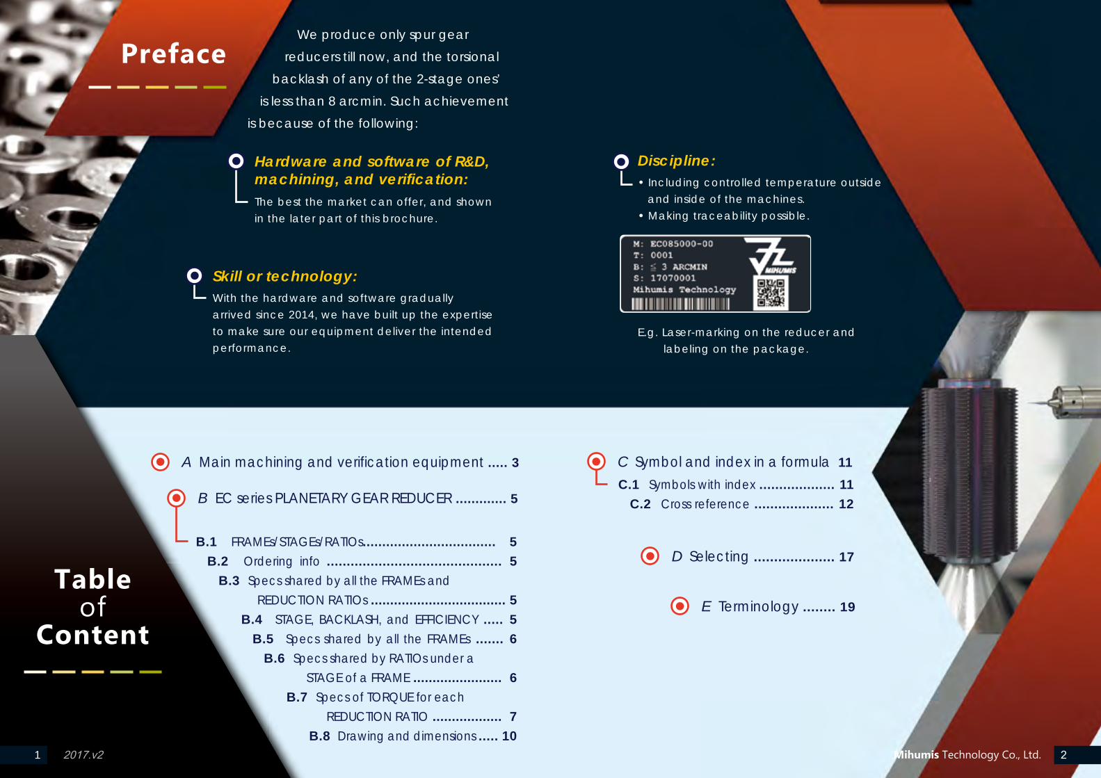
We produce only spur gear
reducers till now, and the torsional
backlash of any of the 2-stage ones’
is less than 8 arcmin. Such achievement
is because of the following:
Hardware and software of R&D, machining, and verification:The best the market can offer, and shown in the later part of this brochure.
Discipline:• Including controlled temperature outside
and inside of the machines.• Making traceability possible.
E.g. Laser-marking on the reducer and
labeling on the package.
Skill or technology:With the hardware and software gradually arrived since 2014, we have built up the expertise to make sure our equipment deliver the intended performance.
2017.v21 2
Preface
Tableof
Content
Mihumis Technology Co., Ltd.
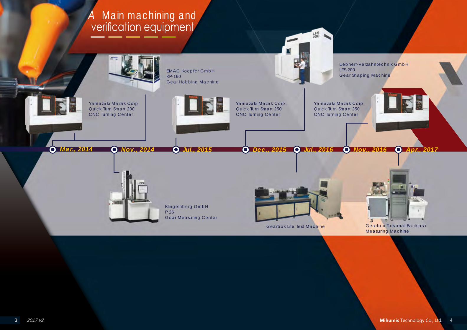
Yamazaki Mazak Corp. Quick Turn Smart 200 CNC Turning Center
EMAG Koepfer GmbHKP-160 Gear Hobbing Machine
Klingelnberg GmbHP 26Gear Measuring Center
Liebherr-Verzahntechnik GmbHLFS-200Gear Shaping Machine
Gearbox Life Test Machine Gearbox Torsional Backlash Measuring Machine
Mar., 2014 Jul., 2016Nov., 2014 Jul., 2015 Dec., 2015 Nov., 2016 Apr., 2017
Yamazaki Mazak Corp. Quick Turn Smart 250 CNC Turning Center
Yamazaki Mazak Corp. Quick Turn Smart 250 CNC Turning Center
3
A Main machining and verification equipment
42017.v2 Mihumis Technology Co., Ltd.
2017.v25 6
B EC series PLANETARY GEAR REDUCER
Mihumis Technology Co., Ltd.
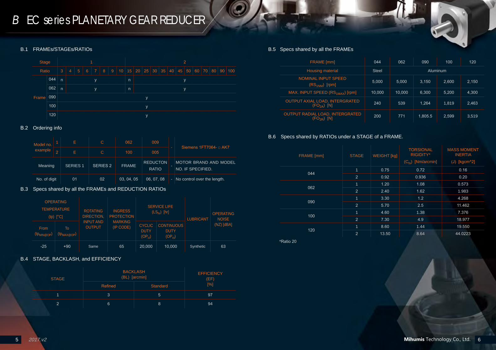
B.1 FRAMEs/STAGEs/RATIOs
Stage 1 2
Ratio 3 4 5 6 7 8 9 10 15 20 25 30 35 40 45 50 60 70 80 90 100
Frame
044 n y n y
062 n y n y
090 y
100 y
120 y
B.2 Ordering info
Model no. example
1 E C 062 009- Siemens 1FT7064- □ AK7
2 E C 100 005
Meaning SERIES 1 SERIES 2 FRAMEREDUCTON
RATIO-
MOTOR BRAND AND MODEL NO. IF SPECIFIED.
No. of digit 01 02 03, 04, 05 06, 07, 08 - No control over the length.
B.3 Specs shared by all the FRAMEs and REDUCTION RATIOs
OPERATING
TEMPERATURE
(tp) [°C]ROTATING
DIRECTION, INPUT AND
OUTPUT
INGRESS PROTECTION
MARKING (IP CODE)
SERVICE LIFE (LShr) [hr]
LUBRICANTOPERATING
NOISE (NZ) [dBA]
From (tpMIN@OP)
To (tpMAX@OP)
CYCLIC DUTY (OPcl)
CONTINUOUS DUTY (OPct)
-25 +90 Same 65 20,000 10,000 Synthetic 63
B.4 STAGE, BACKLASH, and EFFICIENCY
STAGE
BACKLASH (BL) [arcmin]
EFFICIENCY (EF) [%]Refined Standard
1 3 5 97
2 6 8 94
B.5 Specs shared by all the FRAMEs
FRAME [mm] 044 062 090 100 120
Housing material Steel Aluminum
NOMINAL INPUT SPEED(RS1NM) [rpm]
5,000 5,000 3,150 2,600 2,150
MAX. INPUT SPEED (RS1MAX) [rpm] 10,000 10,000 6,300 5,200 4,300
OUTPUT AXIAL LOAD, INTERGRATED (FO2A) [N] 240 539 1,264 1,819 2,463
OUTPUT RADIAL LOAD, INTERGRATED (FO2R) [N] 200 771 1,805.5 2,599 3,519
B.6 Specs shared by RATIOs under a STAGE of a FRAME.
FRAME [mm] STAGE WEIGHT [kg]TORSIONAL RIGIDITY*
(Cts) [Nm/arcmin]
MASS MOMENT INERTIA
(J) [kgcm^2]
0441 0.75 0.72 0.162 0.92 0.936 0.20
0621 1.20 1.08 0.5732 2.40 1.62 1.983
0901 3.30 1.2 4.2682 5.70 2.5 11.462
1001 4.60 1.38 7.3762 7.30 4.9 18.977
1201 8.60 1.44 19.5502 13.50 8.64 44.0223
*Ratio 20
2017.v27 8
B EC series PLANETARY GEAR REDUCER
Mihumis Technology Co., Ltd.
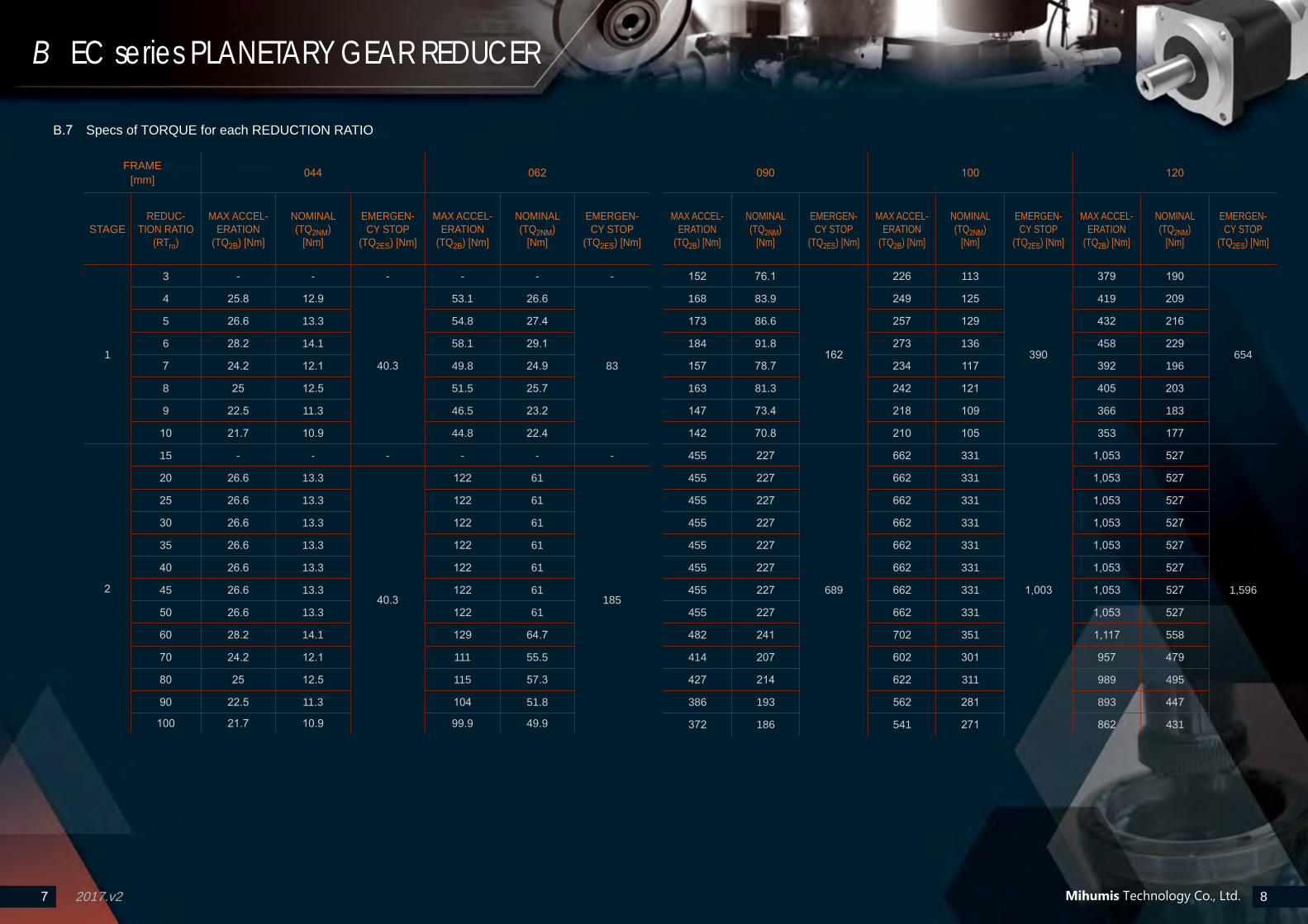
B.7 Specs of TORQUE for each REDUCTION RATIO
FRAME [mm] 044 062
STAGEREDUC-
TION RATIO (RTro)
MAX ACCEL-ERATION
(TQ2B) [Nm]
NOMINAL (TQ2NM)
[Nm]
EMERGEN-CY STOP
(TQ2ES) [Nm]
MAX ACCEL-ERATION
(TQ2B) [Nm]
NOMINAL (TQ2NM)
[Nm]
EMERGEN-CY STOP
(TQ2ES) [Nm]
1
3 - - - - - -
4 25.8 12.9
40.3
53.1 26.6
83
5 26.6 13.3 54.8 27.4
6 28.2 14.1 58.1 29.1
7 24.2 12.1 49.8 24.9
8 25 12.5 51.5 25.7
9 22.5 11.3 46.5 23.2
10 21.7 10.9 44.8 22.4
2
15 - - - - - -
20 26.6 13.3
40.3
122 61
185
25 26.6 13.3 122 61
30 26.6 13.3 122 61
35 26.6 13.3 122 61
40 26.6 13.3 122 61
45 26.6 13.3 122 61
50 26.6 13.3 122 61
60 28.2 14.1 129 64.7
70 24.2 12.1 111 55.5
80 25 12.5 115 57.3
90 22.5 11.3 104 51.8
100 21.7 10.9 99.9 49.9
090 100 120
MAX ACCEL-ERATION
(TQ2B) [Nm]
NOMINAL (TQ2NM)
[Nm]
EMERGEN-CY STOP
(TQ2ES) [Nm]
MAX ACCEL-ERATION
(TQ2B) [Nm]
NOMINAL (TQ2NM)
[Nm]
EMERGEN-CY STOP
(TQ2ES) [Nm]
MAX ACCEL-ERATION
(TQ2B) [Nm]
NOMINAL (TQ2NM)
[Nm]
EMERGEN-CY STOP
(TQ2ES) [Nm]
152 76.1
162
226 113
390
379 190
654
168 83.9 249 125 419 209
173 86.6 257 129 432 216
184 91.8 273 136 458 229
157 78.7 234 117 392 196
163 81.3 242 121 405 203
147 73.4 218 109 366 183
142 70.8 210 105 353 177
455 227
689
662 331
1,003
1,053 527
1,596
455 227 662 331 1,053 527
455 227 662 331 1,053 527
455 227 662 331 1,053 527
455 227 662 331 1,053 527
455 227 662 331 1,053 527
455 227 662 331 1,053 527
455 227 662 331 1,053 527
482 241 702 351 1,117 558
414 207 602 301 957 479
427 214 622 311 989 495
386 193 562 281 893 447
372 186 541 271 862 431
2017.v29 10
B EC series PLANETARY GEAR REDUCER
Mihumis Technology Co., Ltd.
PCDØD6 PC
DØD9
ØD5
ØD
4
ØD
3
ØD
2
ØD
7
ØD
8
M1
M2
H8 H7
H5
H4
H6
H1
H2
H3
D1D10
PCD
ØD
6
PCDØD9
ØD5
ØD
4Ø
D3
ØD
2
ØD
7
ØD
8
M1M2
H8 H7
H5
H4H6
H1
H2
H3
D1D10
PCDØD6
PCDØ
D9
ØD5
ØD
4
ØD
3
ØD
2
ØD
7
ØD
8
M1
M2
H8 H7
H5
H4
H6
H1
H2
H3
D1
ØD
11
D10
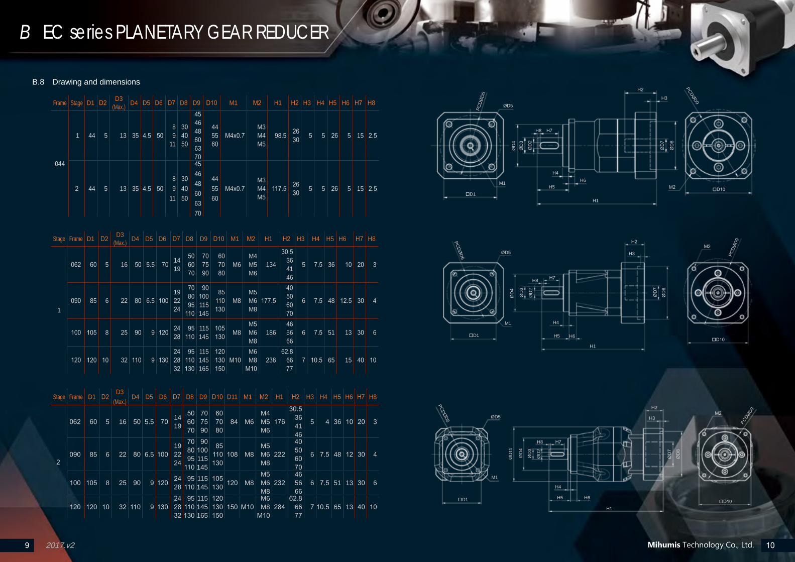
Stage Frame D1 D2 D3(Max.) D4 D5 D6 D7 D8 D9 D10 M1 M2 H1 H2 H3 H4 H5 H6 H7 H8
1
062 60 5 16 50 5.5 70 14 19
5060 70
70 7590
60 70
80M6
M4M5M6
134
30.536
4146
5 7.5 36 10 20 3
090 85 6 22 80 6.5 10019 2224
7080 95
110
90 100115145
85110130
M8M5M6
M8177.5
40 506070
6 7.5 48 12.5 30 4
100 105 8 25 90 9 120 24 28
95110
115 145
105130 M8
M5M6M8
186465666
6 7.5 51 13 30 6
120 120 10 32 110 9 13024 2832
95110130
115145165
120130150
M10M6M8
M10238
62.866 77
7 10.5 65 15 40 10
B.8 Drawing and dimensions
Frame Stage D1 D2 D3(Max.) D4 D5 D6 D7 D8 D9 D10 M1 M2 H1 H2 H3 H4 H5 H6 H7 H8
044
1 44 5 13 35 4.5 5089
11
304050
454648606370
44 55 60
M4x0.7M3 M4M5
98.5 2630 5 5 26 5 15 2.5
2 44 5 13 35 4.5 5089
11
30 4050
454648 606370
4455 60
M4x0.7M3M4M5
117.5 2630 5 5 26 5 15 2.5
Stage Frame D1 D2D3
(Max.) D4 D5 D6 D7 D8 D9 D10 D11 M1 M2 H1 H2 H3 H4 H5 H6 H7 H8
2
062 60 5 16 50 5.5 70 1419
50 6070
707590
60 70 80
84 M6M4M5M6
176
30.5364146
5 4 36 10 20 3
090 85 6 22 80 6.5 100192224
70 8095
110
90100115145
85 110130
108 M8M5 M6M8
222
405060 70
6 7.5 48 12 30 4
100 105 8 25 90 9 120 24 28
95 110
115 145
105 130 120 M8
M5 M6M8
23246 5666
6 7.5 51 13 30 6
120 120 10 32 110 9 13024 28 32
95 110130
115145165
120 130 150
150 M10M6M8
M10284
62.866 77
7 10.5 65 13 40 10
2017.v211 12
C Symbol and index in a formula 1S: Symbols;I: Index
Mihumis Technology Co., Ltd.
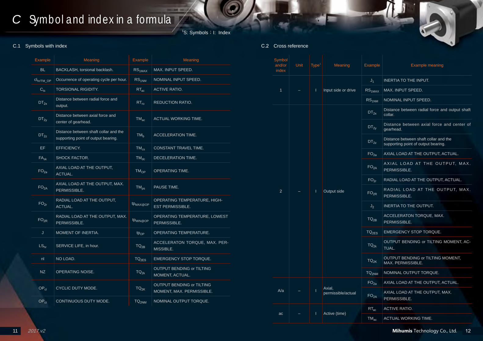
C.1 Symbols with index
Example Meaning Example Meaning
BL BACKLASH, torsional backlash. RS1MAX MAX. INPUT SPEED.
clhr/TM_OP Occurrence of operating cycle per hour. RS1NM NOMINAL INPUT SPEED.
Cts TORSIONAL RIGIDITY. RTac ACTIVE RATIO.
DT2xDistance between radial force and output.
RTro REDUCTION RATIO.
DT2yDistance between axial force and center of gearhead.
TMac ACTUAL WORKING TIME.
DT2zDistance between shaft collar and the supporting point of output bearing.
TMb ACCELERATION TIME.
EF EFFICIENCY. TMcs CONSTANT TRAVEL TIME.
FAsk SHOCK FACTOR. TMdc DECELERATION TIME.
FO2aAXIAL LOAD AT THE OUTPUT, ACTUAL.
TMOP OPERATING TIME.
FO2AAXIAL LOAD AT THE OUTPUT, MAX. PERMISSIBLE.
TMps PAUSE TIME.
FO2rRADIAL LOAD AT THE OUTPUT, ACTUAL.
tpMAX@OPOPERATING TEMPERATURE, HIGH-EST PERMISSIBLE.
FO2RRADIAL LOAD AT THE OUTPUT, MAX. PERMISSIBLE.
tpMIN@OPOPERATING TEMPERATURE, LOWEST PERMISSIBLE.
J MOMENT OF INERTIA. tpOP OPERATING TEMPERATURE.
LShr SERVICE LIFE, in hour. TQ2BACCELERATON TORQUE, MAX. PER-MISSIBLE.
nl NO LOAD. TQ2ES EMERGENCY STOP TORQUE.
NZ OPERATING NOISE. TQ2kOUTPUT BENDING or TILTING MOMENT, ACTUAL.
OPcl CYCLIC DUTY MODE. TQ2KOUTPUT BENDING or TILTING MOMENT, MAX. PERMISSIBLE.
OPct CONTINUOUS DUTY MODE. TQ2NM NOMINAL OUTPUT TORQUE.
C.2 Cross reference
Symbol and/or index
Unit Type1 Meaning Example Example meaning
1 – I Input side or drive
J1 INERTIA TO THE INPUT.
RS1MAX MAX. INPUT SPEED.
RS1NM NOMINAL INPUT SPEED.
2 – I Output side
DT2xDistance between radial force and output shaft collar.
DT2yDistance between axial force and center of gearhead.
DT2zDistance between shaft collar and the supporting point of output bearing.
FO2a AXIAL LOAD AT THE OUTPUT, ACTUAL.
FO2AA X I A L L O A D AT T H E O U T P U T, M A X . PERMISSIBLE.
FO2r RADIAL LOAD AT THE OUTPUT, ACTUAL.
FO2RRADIAL LOAD AT THE OUTPUT, MAX. PERMISSIBLE.
J2 INERTIA TO THE OUTPUT.
TQ2BACCELERATON TORQUE, MAX. PERMISSIBLE.
TQ2ES EMERGENCY STOP TORQUE.
TQ2kOUTPUT BENDING or TILTING MOMENT, AC-TUAL.
TQ2KOUTPUT BENDING or TILTING MOMENT, MAX. PERMISSIBLE.
TQ2NM NOMINAL OUTPUT TORQUE.
A/a – I Axial, permissible/actual
FO2a AXIAL LOAD AT THE OUTPUT, ACTUAL.
FO2AAXIAL LOAD AT THE OUTPUT, MAX. PERMISSIBLE.
ac – I Active (time)RTac ACTIVE RATIO.
TMac ACTUAL WORKING TIME.

2017.v213 14
C Symbol and index in a formula 1S: Symbols;I: Index
Mihumis Technology Co., Ltd.
Symbol and/or index
Unit Type1 Meaning Example Example meaning
B/b – I Acceleration (time), permissible/actual
TMb ACCELERATION TIME.
TQ2BACCELERATON TORQUE, MAX. PERMISSIBLE.
BL arcmin S Backlash, torsional backlash BL BACKLASH, torsional backlash.
CNm/
arcminS Rigidity Cts TORSIONAL RIGIDITY.
cl – I Cyclic (duty mode), (time) of a cycle
clhr/TM_OP Occurrence of operating cycle per hour.
OPcl CYCLIC DUTY MODE.
cs – I Constant speed (time) TMcs CONSTANT TRAVEL TIME.
ct – I Continuous (duty mode) OPct CONTINUOUS DUTY MODE.
dc – I Deceleration (time) TMdc DECELERATION TIME.
DTmultiple
unitsS Distance, Travel
DT2xDistance between radial force and output shaft collar.
DT2yDistance between axial force and center of gearhead.
DT2zDis tance between shaf t co l la r and the supporting point of output bearing.
EF % S Efficiency EF EFFICIENCY.
ES – I Emergency stop TQ2ES EMERGENCY STOP TORQUE.
FA – S/I Factor FAsk Shock factor.
FO N S/I Load/Force
FO2a AXIAL LOAD AT THE OUTPUT, ACTUAL.
FO2AAXIAL LOAD AT THE OUTPUT, MAX. PERMISSIBLE.
FO2r RADIAL LOAD AT THE OUTPUT, ACTUAL.
FO2RRADIAL LOAD AT THE OUTPUT, MAX. PERMISSIBLE.
hr hr I Hourclhr/TM_OP Occurrence of operating cycle per hour.
LShr SERVICE LIFE, in hour.
Symbol and/or index
Unit Type1 Meaning Example Example meaning
J kgcm^2 S/I MASS MOMENT OF INERTIA
J1 INERTIA TO THE INPUT.
J2 INERTIA TO THE OUTPUT.
K/k – I Tilting, Rated/ equivalent
TQ2kOUTPUT BENDING or TILTING MOMENT, ACTUAL.
TQ2KOUTPUT BENDING or TILTING MOMENT, MAX. PERMISSIBLE.
LS hr S Service life LShr SERVICE LIFE, in hour.
MAX/ max
– I Maximum, permissible/actual
RS1MAX MAX. INPUT SPEED.
tpMAX@OPOPERATING TEMPERATURE, HIGHEST PERMISSIBLE.
MIN/ min
– I Minimum, permissible/actual tpMIN@OP
OPERATING TEMPERATURE, LOWEST PERMISSIBLE.
nl – S/I No load nl NO LOAD.
NM – I NominalRS1NM NOMINAL INPUT SPEED.
TQ2NM NOMINAL OUTPUT TORQUE.
NZ dBA S Operating noise NZ OPERATING NOISE.
OP – S/I
Duty mode or operation (duration), Number of cycles (per hr or service life)
clhr/TM_OP Occurrence of operating cycle per hour.
OPcl CYCLIC DUTY MODE.
OPct CONTINUOUS DUTY MODE.
TMOP OPERATING TIME.
tpMAX@OPOPERATING TEMPERATURE, HIGHEST PERMISSIBLE.
tpMIN@OPOPERATING TEMPERATURE, LOWEST PERMISSIBLE.
tpOP Operating temperature.
ps – I Pause (time) TMps PAUSE TIME.
2017.v215 16
C Symbol and index in a formula 1S: Symbols;I: Index
Mihumis Technology Co., Ltd.
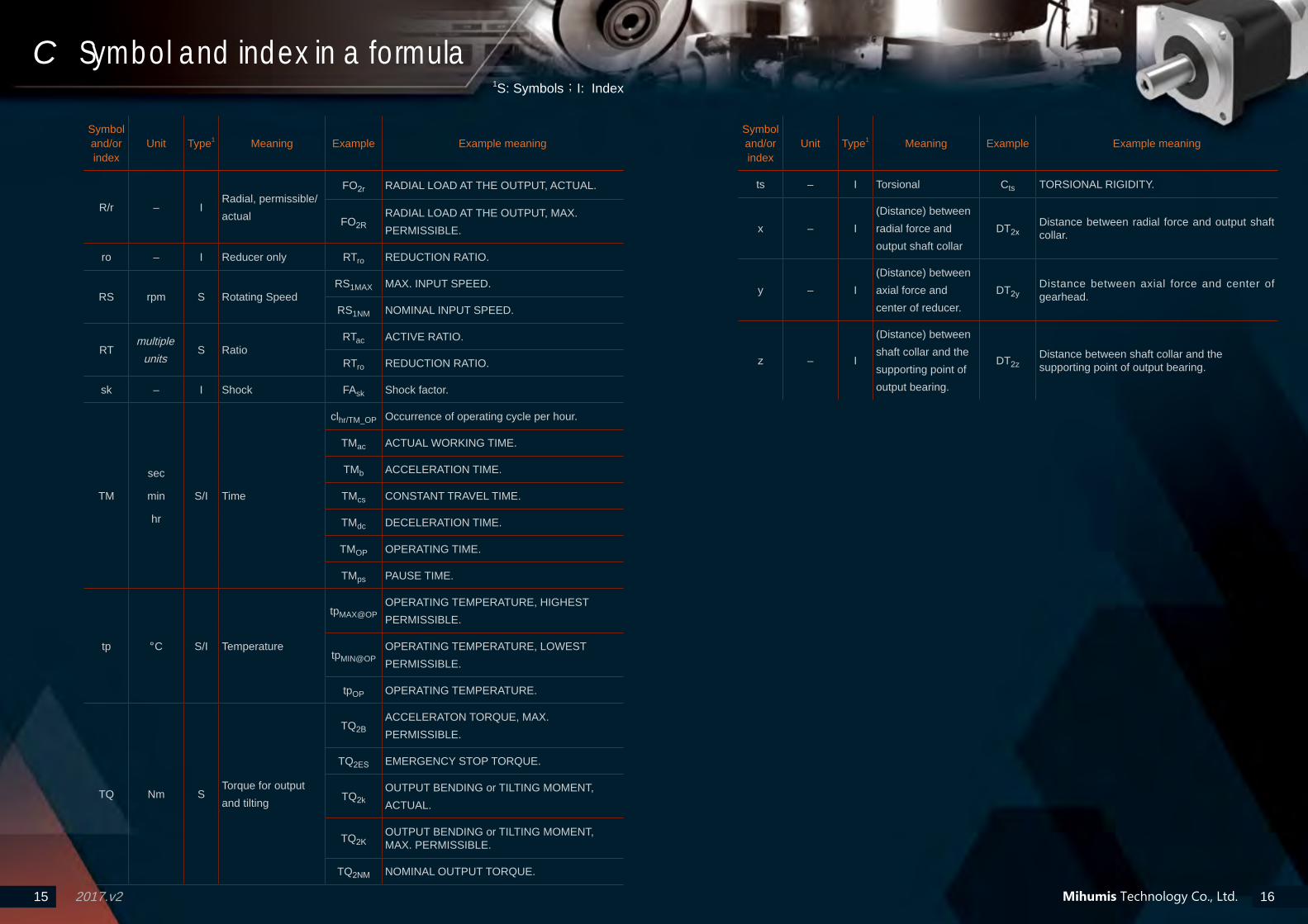
Symbol and/or index
Unit Type1 Meaning Example Example meaning
R/r – IRadial, permissible/ actual
FO2r RADIAL LOAD AT THE OUTPUT, ACTUAL.
FO2RRADIAL LOAD AT THE OUTPUT, MAX. PERMISSIBLE.
ro – I Reducer only RTro REDUCTION RATIO.
RS rpm S Rotating SpeedRS1MAX MAX. INPUT SPEED.
RS1NM NOMINAL INPUT SPEED.
RTmultiple
unitsS Ratio
RTac ACTIVE RATIO.
RTro REDUCTION RATIO.
sk – I Shock FAsk Shock factor.
TM
sec
min
hr
S/I Time
clhr/TM_OP Occurrence of operating cycle per hour.
TMac ACTUAL WORKING TIME.
TMb ACCELERATION TIME.
TMcs CONSTANT TRAVEL TIME.
TMdc DECELERATION TIME.
TMOP OPERATING TIME.
TMps PAUSE TIME.
tp °C S/I Temperature
tpMAX@OPOPERATING TEMPERATURE, HIGHEST PERMISSIBLE.
tpMIN@OPOPERATING TEMPERATURE, LOWEST PERMISSIBLE.
tpOP OPERATING TEMPERATURE.
TQ Nm STorque for output and tilting
TQ2BACCELERATON TORQUE, MAX. PERMISSIBLE.
TQ2ES EMERGENCY STOP TORQUE.
TQ2kOUTPUT BENDING or TILTING MOMENT, ACTUAL.
TQ2KOUTPUT BENDING or TILTING MOMENT, MAX. PERMISSIBLE.
TQ2NM NOMINAL OUTPUT TORQUE.
Symbol and/or index
Unit Type1 Meaning Example Example meaning
ts – I Torsional Cts TORSIONAL RIGIDITY.
x – I(Distance) between radial force and output shaft collar
DT2xDistance between radial force and output shaft collar.
y – I(Distance) between axial force and center of reducer.
DT2yDistance between axial force and center of gearhead.
z – I
(Distance) between shaft collar and the supporting point of output bearing.
DT2zDistance between shaft collar and the supporting point of output bearing.
17 182017.v217 18
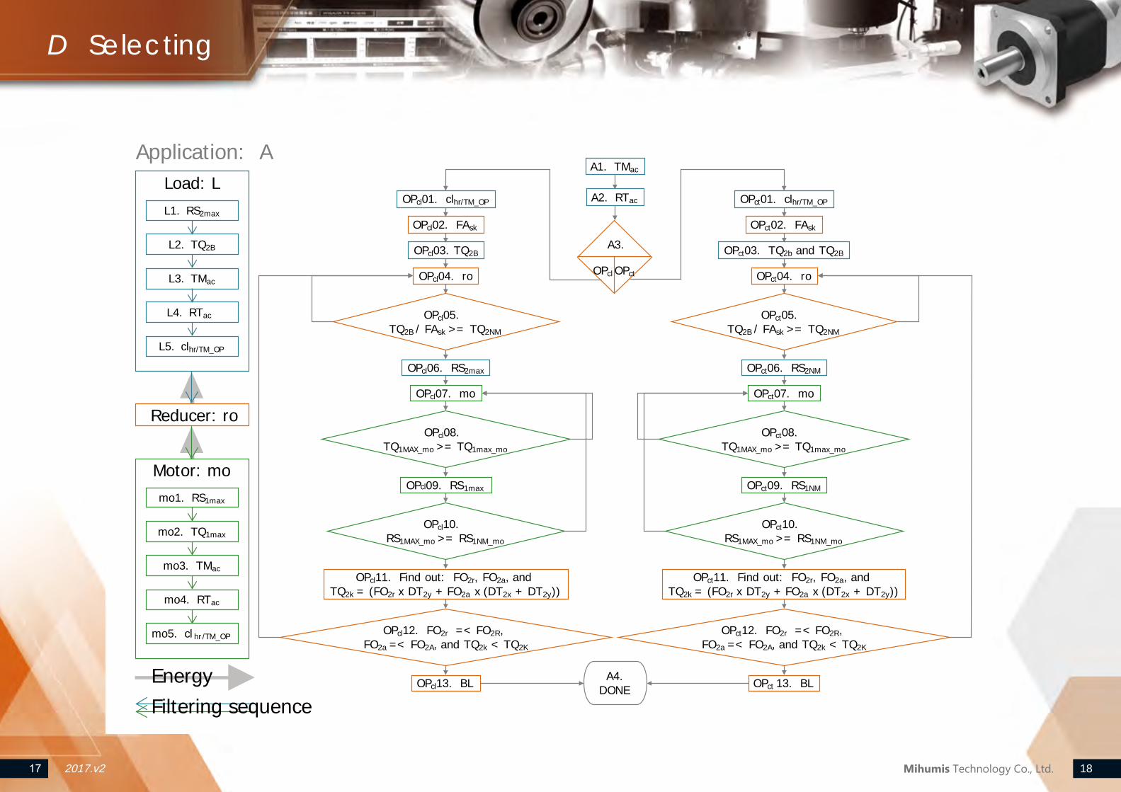
Load: L
Reducer: ro
Motor: mo
A1. TMac
A4. DONE
A2. RTacOPcl01. clhr/TM_OP
OPcl02. FAsk
OPcl06. RS2max
OPcl04. ro
OPcl09. RS1max
OPcl03. TQ2B
L3. TMac
L4. RTac
L5. clhr/TM_OP
L2. TQ2B
L1. RS2maxOPct01. clhr/TM_OP
OPct02. FAsk
OPct06. RS2NM
OPct04. ro
OPct09. RS1NM
OPct03. TQ2b and TQ2B
OPct08. TQ1MAX_mo >= TQ1max_mo
OPcl08. TQ1MAX_mo >= TQ1max_mo
OPcl10. RS1MAX_mo >= RS1NM_mo
OPct10. RS1MAX_mo >= RS1NM_mo
mo3. TMac
mo4. RTac
mo5. cl hr/TM_OP
mo2. TQ1max
mo1. RS1max
OPcl07. mo OPct07. mo
Application: A
OPct05. TQ2B / FAsk >= TQ2NM
OPcl05. TQ2B / FAsk >= TQ2NM
OPcl11. Find out: FO2r, FO2a, and TQ2k = (FO2r x DT2y + FO2a x (DT2x + DT2y))
OPct11. Find out: FO2r, FO2a, and TQ2k = (FO2r x DT2y + FO2a x (DT2x + DT2y))
OPcl12. FO2r =< FO2R, FO2a =< FO2A, and TQ2k < TQ2K
OPct12. FO2r =< FO2R, FO2a =< FO2A, and TQ2k < TQ2K
OPcl13. BL OPct 13. BLEnergyFiltering sequence
A3.
OPcl OPct
D Selecting
Mihumis Technology Co., Ltd.
19 202017.v219 20
E Terminology
Mihumis Technology Co., Ltd.
# Terminology Criteria, explanation, or example.
BACKLASH (BL) [arcmin] or [’]
ANGULAR MINUTE [arcmin] or [’]
2 BACKLASH (Torsional backlash) (BL)
2.1 Is the maximum angle of torsion of the output shaft in relation to the input, and measure by the angle.
2.2 The main factor is the face clearance among all the gears in a gearbox.
3 ANGULAR MINUTE
3.1 1 degree = 60 angular minutes or arcmin = 60’. Angular minute can be used as the unit for the accuracy of a gearbox: When BACKLASH (BL) of a REDUCER is 1 arcmin, the deviation of an output cycle of it will be 1/60 degree, and it influences also the arc length by 1/60° .
3.2 The formula concerning the torsional backlash and output shaft arc length deviation is: b = 2 • π • r • α° / 360° .
4 Example: When output shaft radius is 19mm, and the BACKLASH (BL) = 3’, the deviation at the shift will be = 2 • 19mm • 3.14 • 3’ / 60° / 360° = 0.01657mm.
5 Due to the difference on engagement character, helical gear REDUCER can usually achieve lower BACKLASH (BL), or making their higher BACKLASH (BL) harder to be measured, than those of spur ones.With high precision and accuracy of machining, and optimized mesh, the spur gear REDUCERs of Mihumis Technology achieve genuinely low BACKLASH (BL).
03 EFFICIENCY (EF) [%]
1 The ratio of output to input power. The power lost due to friction is unavoidable, and thus the EFFICIENCY(EF) is always less than 1 or 100%.
2 Info in this brochure is based on NOMINAL INPUT SPEED, full load, and no friction.
04 EMERGENCY STOP TORQUE (TQ2ES) [Nm]
1 The maximum permissible torque at the output side of the REDUCER.
2 Must not exceed 1,000 times during the SERVICE LIFE (LShr) of a REDUCER.
05 INGRESS PROTECTION MARKING (IP CODE)
1 The IP Code, International Protection Marking, IEC standard 60529, classifies and rates the degree of protection provided against intrusion (body parts such as hands and fingers), dust, accidental contact, and water by mechanical casings and electrical enclosures. The first digit indicates the protection level against ingress of solid objects, while the second for liquid.
2 Example:
2.1 An electrical socket rated IP22 is protected against insertion of fingers and will not be damaged or become unsafe during a specified test in which it is exposed to vertically or nearly vertically dripping water. IP22 or 2X are typical minimum requirements for the design of electrical accessories for indoor use.
2.2 A particular cellular phone rated at IP67 is“dust resistant”and can be “immersed in 1.5 meters of freshwater for up to 30 minutes”.
# Terminology Criteria, explanation, or example.
01 NOMINAL OUTPUT TORQUE (TQ2NM) [Nm]
ACCELERATION TORQUE, MAX. PERMISSIBLE (TQ2B) [Nm]
OCCURRENCE OF OPERATION CYCLE PER HOUR (clhr/TM_OP)
SHOCK FACTOR (FAsk)
1 In the CYCLIC DUTY (OPcl) the MAX PERMISSIBLE ACCELERATION TORQUE (TQ2B) can be applied to a REDUCER shortly, and within 1,000 times per hour. clhr/TM_OP <=1,000
2 NOMINAL OUTPUT TORQUE (TQ2NM) is the upper limit for the output and continuous output of a REDUCER under CONTINUOUS DUTY (OPct).
3 NOMINAL OUTPUT TORQUE <= ACCELERATION TORQUE, MAX. PERMISSIBLE TQ2NM <= TQ2B
4 No matter a reducer is working under CYCLIC DUTY (OPcl) or CONTINUOUS DUTY (OPct), the frequency of change on the transmitting SPEED (RS) and TORQUE (TQ) needed be taken into consideration.
5 Apply SHOCK FACTOR (FAsk) to lower the MAX. PERMISSIBLE ACCELERATION TORQUE (TQ2B) when the OCCURRENCE OF OPERATION CYCLE PER HOUR (clhr/TM_OP) needs to be larger than 1,000.
6 Divide an hour with OPERATING TIME (TMOP) i.e. from resting to ACCELERATION TIME (TMb), to CONSTANT TRAVEL TIME (TMcs), to DECELERATION TIME (TMdc), to PAUSE TIME (TMps) = OCCURRENCE OF OPERATION CYCLE PER HOUR. clhr/TM_OP = 1hr / TMOP
7 Find from the following the OCCURRENCE OF OPERATION CYCLE PER HOUR (clhr/TM_OP) and then the matching SHOCK FACTOR (FAsk): clhr/TM_OP FAsk
1 ~ 1,000 1.0 1,001 ~ 1,500 1.1 1,501 ~ 2,000 1.3 2,001 ~ 3,000 1.6 3,001 ~ 5,000 1.8
8 TQ2B >= TQ2b x FAsk MAX. PERMISSIBLE ACCELERATION TORQUE >= ACTUAL ACCELERATION TORQUE x SHOCK FACTOR TQ2b <= TQ2B / FAskACTURAL ACCELERATION TORQUE <= MAX. PERMISSIBLE ACCELERATION TORQUE / SHOCK FACTOR
02 FACE CLEARANCE BETWEEN GEAR TOOTH [length unit ]
1 GEAR TEETH FACE CLEARANCE
1.1 Is measured by the distance instead of the angle between meshing teeth of a pair of gears.
1.2 Its functions are: A. absorbing the minute deviancy
of the teeth. B. absorbing the nonconformity between
the centers of the teeth. C. absorbing the thermal-deformation of the teeth during operation. D. allowing a room for lubricant film to prevent jam.

21 222017.v221 22
E Terminology
Mihumis Technology Co., Ltd.
# Terminology Criteria, explanation, or example.
06 MASS MOMENT OF INERTIA (J) [kgcm^2]
1 The MASS MOMENT OF INERTIA (J) is a measurement of the effort applied by an object to maintain its momentary condition (at rest or moving).
2 A parameter given in this brochure is the system MASS MOMENT OF INERTIA (J) of the concerning REDUCER and the combination of those of all the revolving and applicable parts in that REDUCER.
07 MAX. INPUT SPEED (RS1MAX) [rpm]
1 Applicable to only CYCLIC DUTY (OPcl) and not CONTINUOUS DUTY (OPct).
2 Under the CYCLIC DUTY (OPcl) the input speed can be momentarily exceeds the rated and shortly close to, but never exceeds, the MAX. INPUT SPEED (RS1MAX).
08 MAX. OUTPUT TORQUE (TQ2MAX)
1 Means the largest torque can be transmitted by the REDUCER. For applications that copes with minor increase over time on the TORSIONAL BACKLASH (BL) this value can be chosen.
09 NOMINAL INPUT SPEED (RS1NM) [rpm]
1 No exceeding NOMINAL INPUT SPEED (RS1NM) under CONTINUOUS DUTY (OPct).
2 Under the standard warranty conditions, the housing temperature of a reducer should not exceed 90ºC (OPERATING TEMPERATURE, HIGHEST PERMISSIBLE (tpMAX@OP)).
3 Might need to take the ambient temperature into consideration.
10 ACTUAL WORKING TIME (TMac) [sec/min/hr]
ACTIVE RATIO (RTac) [%]
OPERATING MODES (OP)
CONTINUOUS DUTY (OPct)
CYCLIC DUTY (OPcl)
1 Depending on the ACTUAL WORKING TIME (TMac) and ACTIVE RATIO (RTac) [%] to decide an operation is CONTINUOUS DUTY (OPct) or CYCLIC DUTY (OPcl).
2 CYCLIC DUTY (OPcl) means the ACTIVE RATIO (RTac) < 60% and ACTUAL WORKING TIME (TMac) < 20 min.
CONTINUOUS DUTY (OPct) means the ACTIVE RATIO (RTac) >= 60% or ACTUAL WORKING TIME (TMac) >= 20 min.
3 Formulae: TMb + TMcs + TMdc = TMac ACCELERATION TIME + CONSTANT TRAVEL TIME + DECELERATION TIME = ACTUAL WORKING TIME
TMac + TMps = TMOP ACTUAL WORKING TIME + PAUSE TIME = OPERATING TIME
TMac / TMOP = RTac ACTUAL WORKING TIME / OPERATING TIME = ACTIVE RATIO
3.1 TMb ACCELERATION TIME
3.2 TMcs CONSTANT TRAVEL TIME
3.3 TMdc DECELERATION TIME
3.4 TMac ACTUAL WORKING TIME
3.5 TMps PAUSE TIME
3.6 TMOP OPERATING TIME
3.7 RTac ACTIVE RATIO
# Terminology Criteria, explanation, or example.
11 OPERATING NOISE (NZ) [dBA]
1 Measured from REDUCTION RATIO (RTro) = 10/100, at one meter and NOMINAL INPUT SPEED (RS1NM), with no load (nl).
2 Influences by its size, REDUCTION RATIO (RTro), and INPUT SPEED (RS1). The smaller the REDUCTION RATIO (RTro), the bigger the size and the faster the INPUT SPEED (RS1), the louder the OPERATING NOISE (NZ) .
3 Keeping the other conditions the same, usually it’s easier for a gear box with helical gears to be quieter than those with spur ones. Nevertheless, with optimized design, machining, and assembly, a spur-geared REDUCER of Mihumis can usually offer better quietness than most of the helical ones in the market, no matter when it is brand new or throughout its SERVICE LIFE (LShr) .
RS1MAX
TQ2ESTQ2B
RS
TQ2
FO2R/r
TMb TMcs TMdc TMps
RS1b
RS1cs
RS1dc
TM
-TQ2ES
-TQ2B
TM
TM
FO2R
FO2A/a TM
FO2A
-FO2A
TMac
TMOP
RS2b
-RS2b
23 242017.v223 24
E Terminology
Mihumis Technology Co., Ltd.
# Terminology Criteria, explanation, or example.
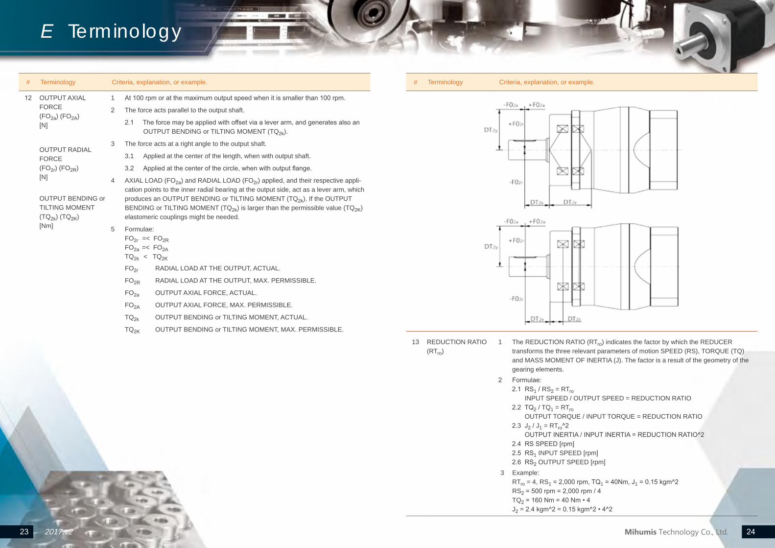
12 OUTPUT AXIAL FORCE (FO2a) (FO2A) [N]
OUTPUT RADIAL FORCE (FO2r) (FO2R) [N]
OUTPUT BENDING or TILTING MOMENT (TQ2k) (TQ2K) [Nm]
1 At 100 rpm or at the maximum output speed when it is smaller than 100 rpm.
2 The force acts parallel to the output shaft.
2.1 The force may be applied with offset via a lever arm, and generates also an OUTPUT BENDING or TILTING MOMENT (TQ2k).
3 The force acts at a right angle to the output shaft.
3.1 Applied at the center of the length, when with output shaft.
3.2 Applied at the center of the circle, when with output flange.
4 AXIAL LOAD (FO2a) and RADIAL LOAD (FO2r) applied, and their respective appli-cation points to the inner radial bearing at the output side, act as a lever arm, which produces an OUTPUT BENDING or TILTING MOMENT (TQ2k). If the OUTPUT BENDING or TILTING MOMENT (TQ2k) is larger than the permissible value (TQ2K) elastomeric couplings might be needed.
5 Formulae: FO2r =< FO2R FO2a =< FO2A TQ2k < TQ2K
FO2r RADIAL LOAD AT THE OUTPUT, ACTUAL.
FO2R RADIAL LOAD AT THE OUTPUT, MAX. PERMISSIBLE.
FO2a OUTPUT AXIAL FORCE, ACTUAL.
FO2A OUTPUT AXIAL FORCE, MAX. PERMISSIBLE.
TQ2k OUTPUT BENDING or TILTING MOMENT, ACTUAL.
TQ2K OUTPUT BENDING or TILTING MOMENT, MAX. PERMISSIBLE.
# Terminology Criteria, explanation, or example.
13 REDUCTION RATIO (RTro)
1 The REDUCTION RATIO (RTro) indicates the factor by which the REDUCER transforms the three relevant parameters of motion SPEED (RS), TORQUE (TQ) and MASS MOMENT OF INERTIA (J). The factor is a result of the geometry of the gearing elements.
2 Formulae:2.1 RS1 / RS2 = RTro INPUT SPEED / OUTPUT SPEED = REDUCTION RATIO2.2 TQ2 / TQ1 = RTro OUTPUT TORQUE / INPUT TORQUE = REDUCTION RATIO2.3 J2 / J1 = RTro^2 OUTPUT INERTIA / INPUT INERTIA = REDUCTION RATIO^22.4 RS SPEED [rpm] 2.5 RS1 INPUT SPEED [rpm]2.6 RS2 OUTPUT SPEED [rpm]
3 Example: RTro = 4, RS1 = 2,000 rpm, TQ1 = 40Nm, J1 = 0.15 kgm^2 RS2 = 500 rpm = 2,000 rpm / 4 TQ2 = 160 Nm = 40 Nm • 4 J2 = 2.4 kgm^2 = 0.15 kgm^2 • 4^2
25 262017.v225 26
E Terminology
Mihumis Technology Co., Ltd.
# Terminology Criteria, explanation, or example.
14 SERVICE LIFE (LShr) [hr]
1 Indicates the life span in hour.
2 When the OPERATION MODE (OP), OUTPUT TORQUE (TQ2), INPUT SPEED (RS1), and TEMPERATURE (tp) comply to this brochure, the SERVICE LIFE (LShr) is then decided by the influence from OUTPUT AXIAL LOAD (FO2a), RADIAL LOAD AT THE OUTPUT, ACTUAL (FO2r) and the BENDING or OUTPUT TILTING MOMENT (TQ2k) to the output bearing.
15 SYNCHRONIZATION ERROR
1 The synchronization error equals to the variations in speed measured between the input and output during one revolution of the output shaft, and is caused by manufacturing tolerances and results in minute angular deviations and fluctuations in ratio.
16 TEMPERATURE (tp) [°C]
1 Indicates the temperature on the surface of a REDUCER.
2 OPERATION TEMPERATURES (tpOP) are decided by the lubricant and seal used.
3 Related to:
3.1 (tpMAX@OP) OPERATING TEMPERATURE, HIGHEST PERMISSIBLE. [°C]
3.2 (tpMIN@OP) OPERATING TEMPERATURE, LOWEST PERMISSIBLE. [°C]
17 TORQUE (TQ)
1 Indicates in this catalogue the input and output forces of a REDUCER or the tilting forces applied to the REDUCER in an application.
18 TORSIONAL RIGIDITY (Cts) [Nm/arcmin]
1 TORSIONAL RIGIDITY (Cts) [Nm/arcmin] shows the torque required to turn the output shaft by one angular minute.
2 A set of shaft responses to torque firstly with distortion before rotation. The degree to the resistance against that distortion or torque equals to the degree of the TORSIONAL RIGIDITY (Cts).
MEMO