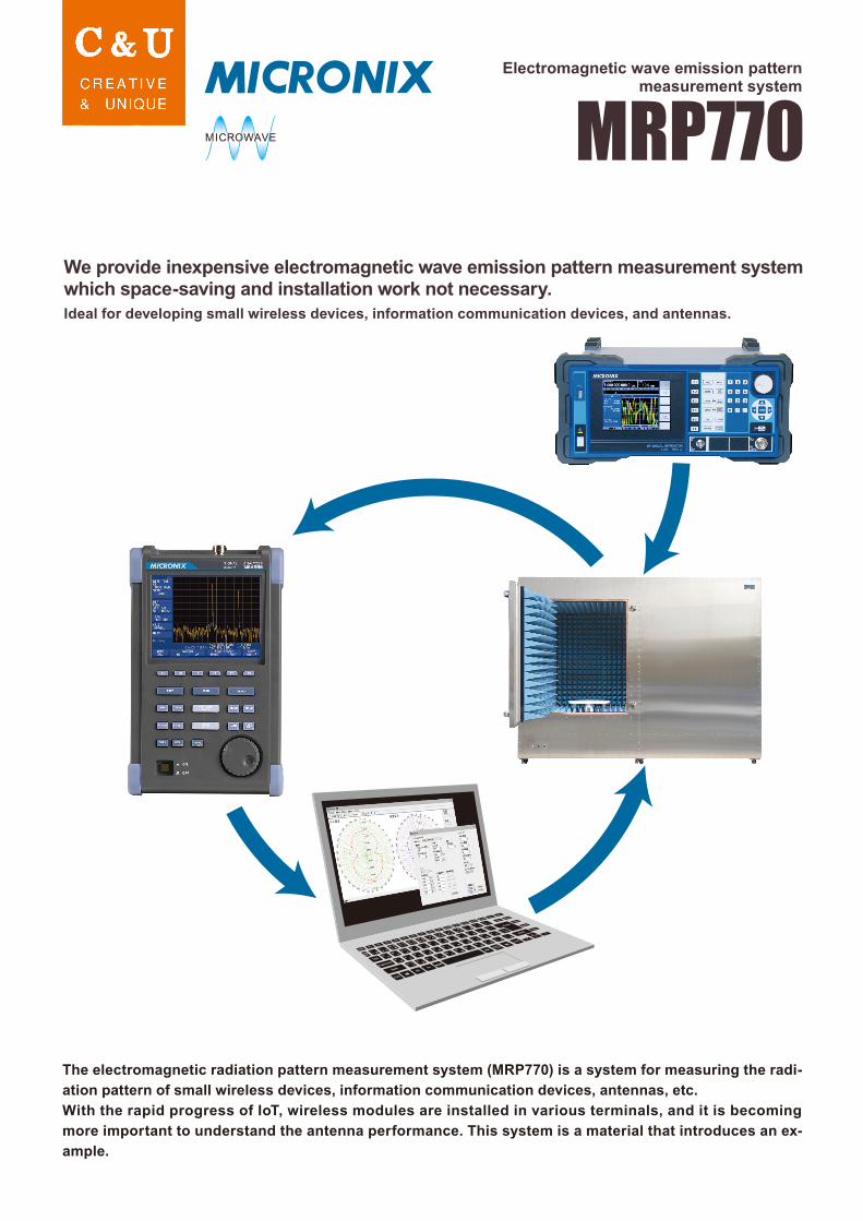
we provide inexpensive electromagnetic wave emission
TRANSCRIPT
Electromagnetic wave emission patternmeasurement system
We provide inexpensive electromagnetic wave emission pattern measurement systemwhich space-saving and installation work not necessary.
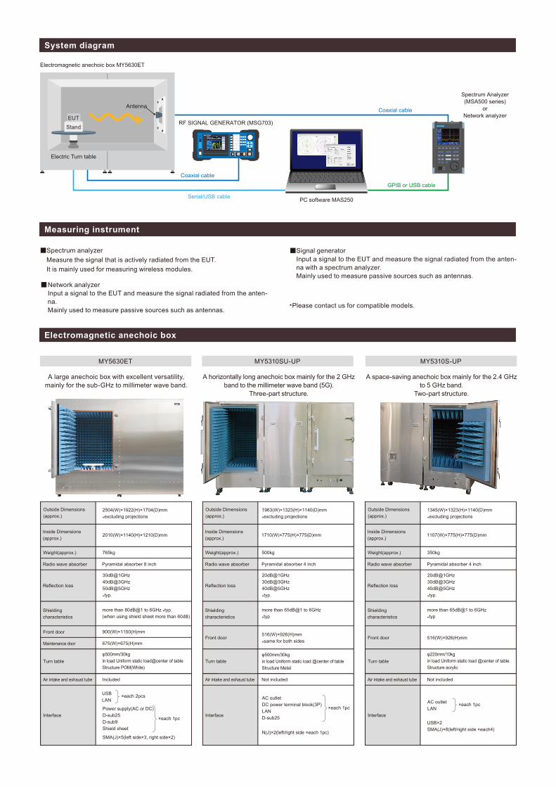
System diagram
Measuring instrument
Electromagnetic anechoic box
Electromagnetic anechoic box MY5630ET
PC software MAS250
Spectrum Analyzer(MSA500 series)
orNetwork analyzer
RF SIGNAL GENERATOR (MSG703)
Coaxial cable
Coaxial cable
GPIB or USB cable
Serial/USB cable
Electric Turn table
SMA(J)×5(left side×3, right side×2)
Power supply(AC or DC)D-sub25D-sub9Shield sheet
N(J)×2(left/right side ×each 1pc)
AC outletDC power terminal block(3P)LAND-sub25

PC software MAS250
*MICRONIX Corporation reserves the right to make changes in design, specification and other information without prior notice.
[ Turntable ]・Specify the measurement start position and end position in steps of 1
degree.・The rotation step interval is at least 1 degree.・Set the waiting time in ms unit until the angle to be measured is reached
and the spectrum analyzer measurement is started.・Set the measurement direction to either one-way (CCW) or round-trip
(CCW+CW).

Electric turn table Electric turn table
Calibration example of the EIRP
Can be measured radiation electricity of measured device (EUT)in reception system same as calibration.
System configuration (Example of wireless module measurement from 1GHz to 8.5GHz)
Option (Example of anechoic box MY5630ET)
(*1)Include connecting cables and connectors inside shield box.
■ Doubleridge horn antenna set
■ Shield sheet (Maintenance door side) ■ Wooden base
■ Log periodic antenna set
2987-2, KOBIKI-CHO, HACHIOJI-SHI, TOKYO 193-0934 JAPAN
URL : http://www.micronix-jp.com
AGENCY
TEL : +81-42-637-3667 FAX : +81-42-637-0227E-mail : [email protected]
MICRONIX CORPORATION
Received power of RF connector part of Electromagnetic anechoic box through receiving antenna + coaxial cable
・Small antenna suitable for broadband measurement with sharp directivity.
・Mounted on a fixed base, and receive and measure in horizontal / vertical plane using rotating mechanism.
・Antenna evaluation such as mobile phone, wireless LAN terminal, base station.
・Same as shield sheet equipped on the front of main body.・Set on the maintenance door side.・For drawing IF and coaxial, optical fiber and special cable.
・Correspond to high gain, wide bandwidth and high power output.・Mounted on a fixed base, receive in horizontal / vertical plane using rotating mechanism and then measure.
・Combined with SG and high-frequency amplifier, enable to evaluate radiation immunity.
・It is possible to evaluate receiving characteristics of base station and 4K broadcasting equipment.
・Attach around the turntable and prevent interference of cables during rotation.
・Since DUT can be placed once on wooden base between door and turntable, the burden of installation is reduced.
The surface of wooden base is 5mm lower than the surface of turntable.