we start from the ground up
TRANSCRIPT

1
Diseño de pavimentos de concreto: de la teoría a la práctica
TALLER DE DISEÑO DE PAVIMENTOS DE
CONCRETO
November 7, 2014
Robert Rodden, P.E.
Senior Director of
Pavement Technology
We Start from the Ground Up
Subgrade Characteristics
• Goal is uniform support, so control:• Expansive soils
• Frost-susceptible soils
• Pumping
• Wet soil
• Varieties:• Unstabilized
• Stabilized• Cement-Treated
• Lime-Stabilized
Subgrade Design
• During construction concerned with:• Moisture content
• Compaction effort
• Working platform
• Structural design concerned with:• Thickness of any treatment
• Strength (bearing capacity) OR• California bearing ratio (CBR)
• Stiffness (resistance to deformation)• Resistance value (R-value)
• Resilient modulus (MR)
California Bearing Ratio (CBR)
• Bearing capacity relative to well-graded crushed stone
Resistance Value (R-value)
• Resistance to deformation; ratio of transmitted lateral pressure to applied vertical pressure

2
Resilient Modulus (MR)
• Elastic modulus (e.g., stress-strain) under repeated axial cyclical stress
Go-to References on Soils/Subgrade
Then We Might Add a Subbase(or more)
Subbase Characteristics
• Goals are:• Erosion resistance
• Uniform support
• Varieties:• Unstabilized
• Stabilized• Cement-Treated (CTB)
• Asphalt-Treated (ATB)
• Lean Concrete (LCB)
• …Drainable
Subbase Design
• During construction concerned with:• Moisture content
• Compaction effort
• Working platform
• Structural design concerned with:• Thickness and # of layers
• Drainability
• Stiffness (resistance to deformation)• Modulus of elasticity (E)
• Resilient modulus (MR) (unbound)
Drainability
Permeable subbase:Permeability of 350 ft/day (107 m/day)
Problems included unstable construction platform, aggbreakdown in service, infiltration of fines, etc.
Free-draining subbase:Permeability of 50-150 ft/day (15-46 m/day)
in laboratory tests
Can be unstabilized or stabilized
Most agencies have already moved away from permeable in favor of free-draining
3
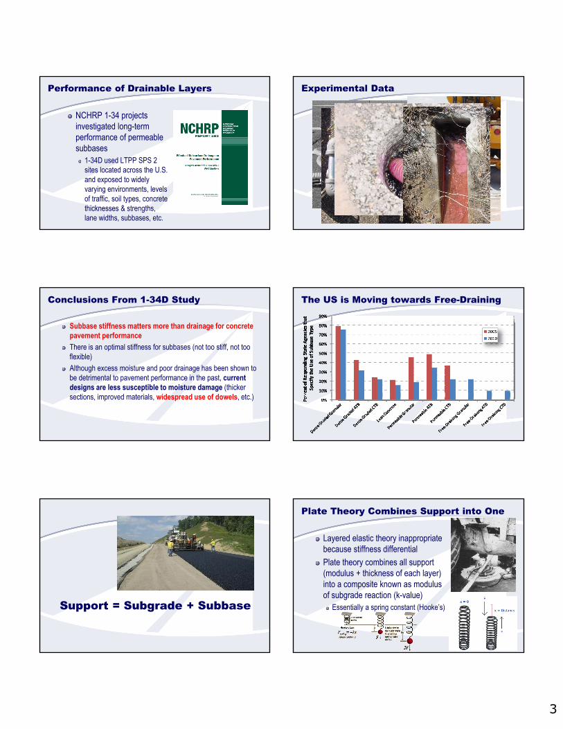
Performance of Drainable Layers
NCHRP 1-34 projects investigated long-term performance of permeable subbases
1-34D used LTPP SPS 2 sites located across the U.S. and exposed to widely varying environments, levels of traffic, soil types, concrete thicknesses & strengths, lane widths, subbases, etc.
Experimental Data
Conclusions From 1-34D Study
Subbase stiffness matters more than drainage for concrete pavement performance
There is an optimal stiffness for subbases (not too stiff, not too flexible)
Although excess moisture and poor drainage has been shown to be detrimental to pavement performance in the past, current designs are less susceptible to moisture damage (thicker sections, improved materials, widespread use of dowels, etc.)
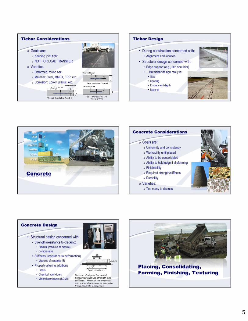
The US is Moving towards Free-Draining
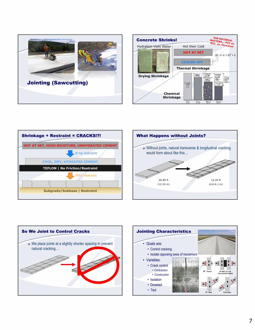
Support = Subgrade + Subbase
Plate Theory Combines Support into One
Layered elastic theory inappropriate because stiffness differential
Plate theory combines all support (modulus + thickness of each layer) into a composite known as modulus of subgrade reaction (k-value)
Essentially a spring constant (Hooke’s)
4
Composite k-value is IterativeConcrete
Asphalt | 6” (150 mm) | 350 ksi (2.4 GPa)
Aggregate | 6” (150 mm) | 30 ksi (207 MPa)
Soil | CBR = 3
Soil | MRSG = 4,118 psi(28 MPa)
Aggregate | 6” | 30ksi
+ 100 psi/in.(27 MPa/m)
= 244 psi/in.(66 MPa/m)
244 psi/in.(66 MPa/m)
+ 244 psi/in.(66 MPa/m)
Asphalt | 6” | 150 ksi
= 388 psi/in.(105 MPa/m)
Add a layer at a time until the composite k-value
immediately beneath the concrete is determined
Note on Subgrade/Subbase Support
Overzealous engineering of a roadbed could have a negative effect once all loads are considered.
Increasing k-value Doesn’t Greatly Decrease the Required Thickness
Concrete pavement design thickness is relatively insensitive to support stiffness (modulus of subgrade reaction), so it is improper engineering to make a subgrade/subbase stronger or thicker in an attempt to decrease concrete pavement thickness…
Analyses conducted in StreetPave
Embedded Steel (if needed)
Dowel Bar Characteristics
Goals are:Faulting resistance
Load transfer
VarietiesShape: Round, plate, etc.
Material: Steel, MMFX, FRP, etc.
Corrosion: Epoxy, zinc, plastic, etc.
Dowel Bar Design
• During construction concerned with:• Alignment and location
• Structural design concerned with:• There or not?
• …But doweldesign is:• Size
• Spacing
• Embedment depth
• Shape
• Material
5
Tiebar Considerations
Goals are:Keeping joint tight
NOT FOR LOAD TRANSFER
Varieties:Deformed, round bar
Material: Steel, MMFX, FRP, etc.
Corrosion: Epoxy, plastic, etc.
Tiebar Design
• During construction concerned with:• Alignment and location
• Structural design concerned with:• Edge support (e.g., tied shoulder)
• …But tiebar design really is:• Size
• Spacing
• Embedment depth
• Material
Concrete
Concrete Considerations
Goals are:Uniformity and consistency
Workability until placed
Ability to be consolidated
Ability to hold edge if slipforming
Finishability
Required strength/stiffness
Durability
Varieties:Too many to discuss
Concrete Design
• Structural design concerned with:• Strength (resistance to cracking)
• Flexural (modulus of rupture)
• Compressive
• Stiffness (resistance to deformation)• Modulus of elasticity (E)
• Property altering additions• Fibers
• Chemical admixtures
• Mineral admixtures (SCMs)Focus in design is hardened properties such as strength and stiffness. Many of the chemical and mineral admixtures also alter fresh concrete properties.
L/3Span Length = L
d=L/3
Placing, Consolidating, Forming, Finishing, Texturing

6
Placing, Consolidating, Forming, Finishing, Texturing Considerations
Goals are:Consistency/uniformity
Smoothness
Varieties:Too many to cover!
Placing, Consolidating, Forming, Finishing, Texturing Design
• During construction concerned with:• EVERYTHING!
• Structural design concerned with:• Thickness
• ???
Can Finish/Texture Affect Design?
Curing
Curing Characteristics
• Goals are:• Prevent (or replenish) loss of moisture
• Maintain a favorable temperature
• Varieties:• Initial cure
• Evaporation retarder
• Misting or fogging
• Final cure• Membrane-forming compounds
• Insulating blankets
• Electric blankets, linseed oil, plastic sheets, wet covers, etc.
Curing Design
• During construction concerned with:• Application rate
• Uniformity of application
• Structural design concerned with:• Strength gain
Age (days)
0
25
50
75
100
125
150
37 28 90 180
Co
mp
ress
ive
Str
engt
h(%
of 2
8-d
ay M
oist
Cu
red) Moist-Cured Entire Time
In Air After 7 days
In Air After 3 days
In Air Entire Time
7
Jointing (Sawcutting)
Concrete Shrinks!
Drying Shrinkage
Hydration Uses Water
Thermal Shrinkage
Hot then Cold
HOT AT SET∆ ∗ ∆ ∗
ChemicalShrinkage
COOLED OFF
Shrinkage + Restraint = CRACKS!?!
HOT AT SET, HIGH MOISTURE, UNHYDRATED CEMENT
COOL, DRY, HYDRATED CEMENT
TEFLON | No Friction/Restraint
If no restraint
With restraint
Subgrade/Subbase | Restraint
What Happens without Joints?
Without joints, natural transverse & longitudinal cracking would form about like this…
40-80 ft
(12-24 m)
15-20 ft
(4.6-6.1 m)
So We Joint to Control Cracks
We place joints at a slightly shorter spacing to prevent natural cracking…
Jointing Characteristics
• Goals are:• Control cracking
• Isolate opposing axes of movement
• Varieties:• Crack control
• Contraction
• Construction
• Isolation
• Doweled
• Tied
8
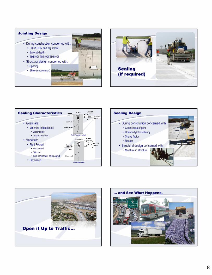
Jointing Design
• During construction concerned with:• LOCATION and alignment
• Sawcut depth
• TIMING! TIMING! TIMING!
• Structural design concerned with:• Spacing
• Skew (uncommon) Sealing(if required)
Sealing Characteristics
• Goals are:• Minimize infiltration of:
• Water and/or
• Incompressibles
• Varieties:• Field Poured:
• Hot-poured
• Silicone
• Two-component cold poured
• Preformed
Field Poured Sealant
Preformed Seal
Sealing Design
• During construction concerned with:• Cleanliness of joint
• Uniformity/Consistency
• Shape factor
• Recess
• Structural design concerned with:• Moisture in structure
Open it Up to Traffic…
… and See What Happens.
9
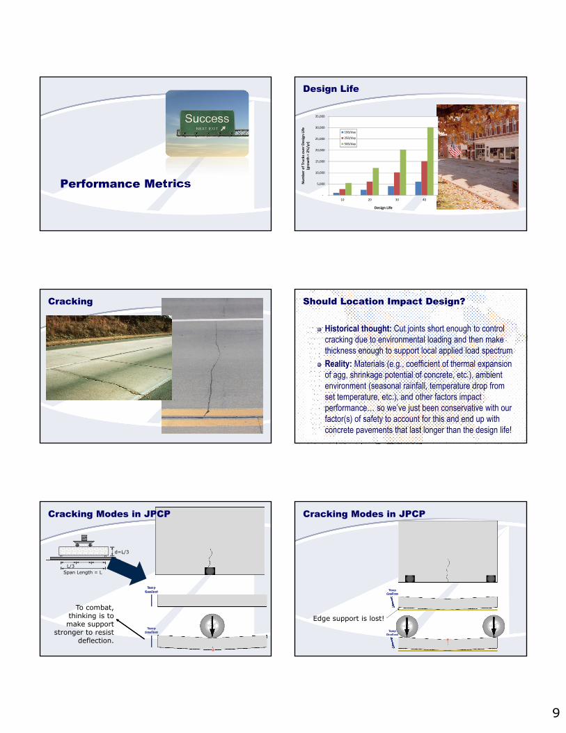
Performance Metrics
Design Life
‐
5,000
10,000
15,000
20,000
25,000
30,000
35,000
10 20 30 40
Number of Trucks over Design Life
(growth = 2%/yr)
Design Life
100/day
250/day
500/day
Cracking Should Location Impact Design?
Historical thought: Cut joints short enough to control cracking due to environmental loading and then make thickness enough to support local applied load spectrum
Reality: Materials (e.g., coefficient of thermal expansion of agg, shrinkage potential of concrete, etc.), ambient environment (seasonal rainfall, temperature drop from set temperature, etc.), and other factors impact performance… so we’ve just been conservative with our factor(s) of safety to account for this and end up with concrete pavements that last longer than the design life!
Cracking Modes in JPCP
L/3Span Length = L
d=L/3
To combat, thinking is to make support
stronger to resist deflection.
Cracking Modes in JPCP
Edge support is lost!
10
Cracking Modes in JPCP Cracking Modes in JPCP
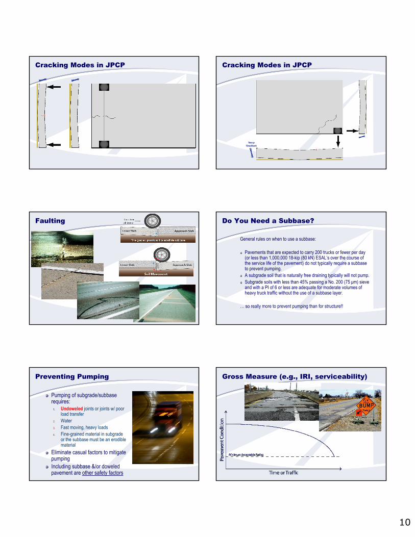
Faulting Do You Need a Subbase?
General rules on when to use a subbase:
Pavements that are expected to carry 200 trucks or fewer per day (or less than 1,000,000 18-kip (80 kN) ESAL’s over the course of the service life of the pavement) do not typically require a subbaseto prevent pumping.A subgrade soil that is naturally free draining typically will not pump.Subgrade soils with less than 45% passing a No. 200 (75 μm) sieve and with a PI of 6 or less are adequate for moderate volumes of heavy truck traffic without the use of a subbase layer.
… so really more to prevent pumping than for structure!!
Preventing Pumping
Pumping of subgrade/subbase requires:
1. Undoweled joints or joints w/ poor load transfer
2. Water3. Fast moving, heavy loads 4. Fine-grained material in subgrade
or the subbase must be an erodible material
Eliminate casual factors to mitigate pumpingIncluding subbase &/or doweled pavement are other safety factors
Gross Measure (e.g., IRI, serviceability)
11
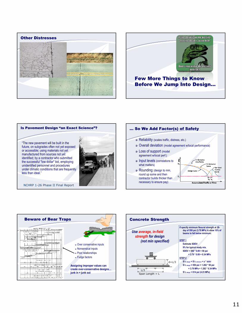
Other Distresses
Few More Things to Know Before We Jump Into Design…
Is Pavement Design “an Exact Science”?
NCHRP 1-26 Phase II Final Report
“The new pavement will be built in the future, on subgrades often not yet exposed or accessible; using materials not yet manufactured from sources not yet identified; by a contractor who submitted the successful "low dollar" bid, employing unidentified personnel and procedures under climatic conditions that are frequently less than ideal.”
… So We Add Factor(s) of Safety
Reliability (scales traffic, distress, etc.)
Overall deviation (model agreement w/local performance)
Loss of support (model agreement w/local perf.)
Input levels (correlations to what matters)
Rounding (design to mm, round up some and then contractor builds thicker than necessary to ensure pay)
Beware of Bear Traps
Over conservative inputs
Nonsensical inputs
Poor relationships
Fudge factors
Assigning improper values can create over-conservative designs… junk in = junk out
Concrete Strength
Use average, in-field strength for design
(not min specified)
L/3Span Length = L
d=L/3
If specify minimum flexural strength at 28-day of 550 psi (3.79 MPa) & allow 10% of beams to fall below minimum:
STEP 1
Estimate SDEV:
9% for typical ready mix.
SDEV = 550 * 0.09 = 50 psi
= 3.79 * 0.09 = 0.34 MPa
STEP 2
S’c design = S’c minimum + z * SDEV
S’c design = 550 psi + 1.282 * 50 psi
= 3.79 MPa + 1.282 * 0.34 MPa
S’c design = 614 psi (4.23 MPa)
12
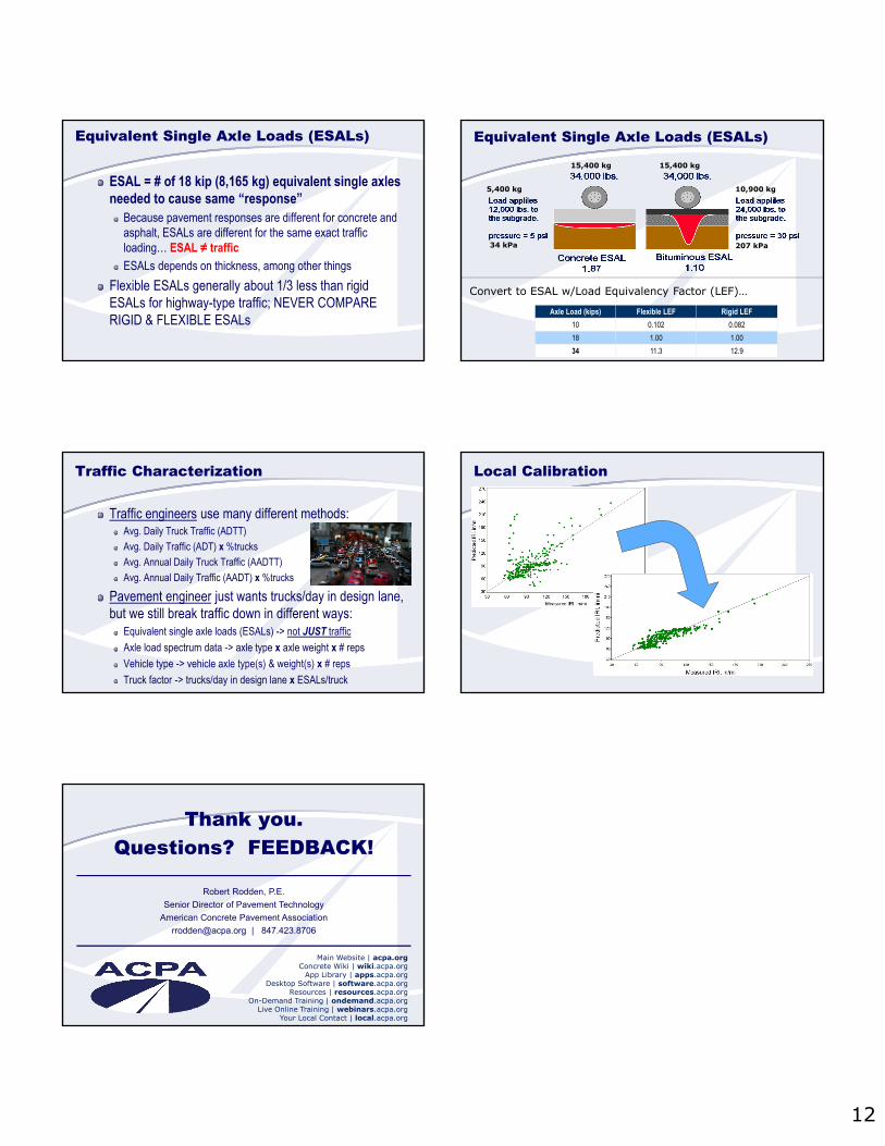
ESAL = # of 18 kip (8,165 kg) equivalent single axles needed to cause same “response”
Because pavement responses are different for concrete and asphalt, ESALs are different for the same exact traffic loading… ESAL ≠ traffic
ESALs depends on thickness, among other things
Flexible ESALs generally about 1/3 less than rigid ESALs for highway-type traffic; NEVER COMPARE RIGID & FLEXIBLE ESALs
Equivalent Single Axle Loads (ESALs) Equivalent Single Axle Loads (ESALs)
15,400 kg 15,400 kg
10,900 kg5,400 kg
34 kPa 207 kPa
Axle Load (kips) Flexible LEF Rigid LEF
10 0.102 0.082
18 1.00 1.00
34 11.3 12.9
Convert to ESAL w/Load Equivalency Factor (LEF)…
Traffic Characterization
Traffic engineers use many different methods:Avg. Daily Truck Traffic (ADTT)
Avg. Daily Traffic (ADT) x %trucks
Avg. Annual Daily Truck Traffic (AADTT)
Avg. Annual Daily Traffic (AADT) x %trucks
Pavement engineer just wants trucks/day in design lane, but we still break traffic down in different ways:
Equivalent single axle loads (ESALs) -> not JUST traffic
Axle load spectrum data -> axle type x axle weight x # reps
Vehicle type -> vehicle axle type(s) & weight(s) x # reps
Truck factor -> trucks/day in design lane x ESALs/truck
Local Calibration
Thank you.Questions? FEEDBACK!
Main Website | acpa.orgConcrete Wiki | wiki.acpa.org
App Library | apps.acpa.orgDesktop Software | software.acpa.org
Resources | resources.acpa.orgOn-Demand Training | ondemand.acpa.org
Live Online Training | webinars.acpa.orgYour Local Contact | local.acpa.org
Robert Rodden, P.E.
Senior Director of Pavement Technology
American Concrete Pavement Association
[email protected] | 847.423.8706