weapon scoring results from a gps acoustic weapons test ... · pdf fileweapon scoring results...
TRANSCRIPT

Weapon Scoring Results from a GPS Acoustic Weapons Test and Training System
Jack R. Kayser, Trident Research
Miguel A. Cardoza, Trident Research William F. Wade, USAF 46th Test Wing
John H. Merts, USAF 46th Test Wing David R. Casey, Sverdrup Technology
BIOGRAPHY Jack Kayser P.E., Ph.D. is a consulting Systems Engineer with Trident Research, as well as a Dam Safety Engineer for the State of Texas. While an Engineering Scientist at the Applied Research Lab (ARL), he developed optical and acoustical instrumentation for the Navy Mobile Instrumentation System (NMIS). At Trident Research, he has developed and implemented acoustical techniques for interpreting weapon impacts as well as the detection of marine mammals. Dr. Kayser has published and presented research in the areas of reliability, deterioration, instrumentation, structures, power storage, education, and construction. He received his Ph.D. in Civil Engineering from the University of Michigan in 1988. Mike Cardoza is a Senior Program Manager with Trident Research LLC, and possesses over 18 years of experience in the design, development and fielding of tactical systems for the DOD. Formerly at Applied Research Lab, Mr. Cardoza led the design and development of two Portable Impact Location System (PILS) at-sea weapons scoring systems for the US Navy. He also served as Program Manager for the implementation of mm-level GPS survey technologies at the White Sands Missile Range, real-time kinematic cm-level positioning technology for the US Navy, and other GPS-based systems for the DOD. Mr. Cardoza received his Bachelors and Masters degrees in Aerospace Engineering from the University of Texas at Austin, and is a graduate of the Defense Systems Management College (DSMC). Bill Wade has worked in the Department of Defense for thirty years developing weapon systems for Air Force aircraft. Mr. Wade has worked on numerous weapon developments and has carried two major weapon systems from concept through development, production, and employment. He currently manages the Offshore Test and Training Area (OTTA) program at Eglin AFB, Florida, which is developing and building the instrumentation and infrastructure for the Eglin Gulf Range. Mr. Wade received his Bachelor of Science in Mechanical Engineering from the University of Nebraska in 1974 and his Master of Business Administration from the University of West Florida in 1980. John H. Merts started employment with the 46th Test Wing at Eglin AFB in 1982 as an Electronics Design
Engineer. Mr. Merts is a previous member of the Range Commanders Council Electronic Trajectory Measurements Group and consults with the group on GPS issues. He is the co-author of a patent on the GPS application of missile / target end-game scoring. His current research topics include precision Time Space Position Information for high dynamic test aircraft, missile end game scoring using GPS raw measurements on missile and target aircraft, and post-mission correction of GPS carrier phase measurements for wrap around antennae effects on missiles. Mr. Merts received his Bachelor of Science in Physics from Florida State University in 1979. David R. Casey has worked in the Department of Defense and as an engineering support contractor for over 42 years, acquiring and fielding U.S. Air Force weapons systems. Mr. Casey now manages the engineering activities of the 46th Test Wing Offshore Test and Training Area (OTTA), which encompasses the assessment of Large Footprint Weapons (LFW) in the Gulf of Mexico. Mr. Casey received his Master of Science degree from Georgia College in 1976 and his Physical Science degree from the University of Northern Colorado in 1962. ABSTRACT A new Offshore Test and Training Area (OTTA) was initiated by the Air Force 46th Test Wing at Eglin Air Force Base, in the Florida Eglin Gulf Range. The OTTA provides a large footprint for testing, training and evaluating standoff weapons. One subsystem deployed in the OTTA was a GPS and acoustical buoy system capable of determining the impact time and location of a weapon within the marine test range. Acoustic event data collected by the buoys is relayed to a command and control station that uses a trilateration algorithm to compute a target score for the event. Buoy real-time scoring is provided to an accuracy of 7 meters, while post-processed scores are accurate to 3 meters. Two weapon tests were conducted in 2004 using the GPS acoustic buoy system. In both cases the impact scores determined from the system were within 1 standard deviation of GPS-derived truth impact scores. Since the buoys are relatively small and light weight, deployment and recovery is rapid and can be accomplished by one

person using a small boat. Test operations can take place at night, in fog, or in moderately heavy sea states. The integration of Commercial-Off–The-Shelf (COTS) technology keeps the unit cost down and facilitates future upgrades. Improvements are currently under development to enhance the capability of the system for sub-meter accurate scoring, munition recovery, and the detection and tracking marine mammals.
A Tactical Acoustic Real-time Geolocation and Training (TARGT) system was developed using COTS-based GPS, acoustic, and RF technologies, combined with custom electronics and embedded processing firmware. This system evolved from a similar system that was developed for the United States Navy to test weapon system targeting in broad ocean environments [Saunders]. The TARGT system was validated first using laboratory, pool and lake based system tests that focused on acoustic detection and timing, as well as data relay and processing. Further tests where conducted at the Eglin Air Force Base (AFB) Offshore Test and Training Area using weapon impacts that were scored independently using a GPS-equipped target barge platform called the Instrumented Target System, shown in Figure 1. Acoustic scores in every evaluated event were within the Circular Error Probability (CEP) of 1 standard deviation of the truth score determined by carrier phase-based GPS processing. The concept of using acoustics to determine precise real-time impact locations has thus been proven valid.
INTRODUCTION Weapons systems that were formerly tested using land based test ranges are frequently being tested in marine continental shelf regions. The change from land based to ocean based testing minimizes issues regarding civilian and environmental disturbance, and provides a broader area to test long-range and large footprint weapons, such as rocket artillery and GPS guided munitions [Fig. 1]. An Offshore Test and Training Area is currently under development along the coast of Northwest Florida, under the direction of the 46th Test Wing at Eglin Air Force Base.
CONCEPT OF A WEAPON SCORING SYSTEM
Background In order to characterize targeting accuracy in an ocean
test, precise surface impact location must be determined. Several methods can be used to measure this location, such as optics, radar, and acoustics. This paper presents the development of an acoustical method for precisely determining weapon impact location. The acoustical method utilizes buoys that are fitted with GPS and acoustic hardware. In order to determine where an impact occurs, the buoys must first detect the underwater sound of the impact, as well as where and when this detection has occurred. Acoustic impact data from multiple buoys is combined in a trilateration algorithm that uses Time Difference of Arrival (TDOA) techniques to compute the location and time of the impact. The accuracy of this method is dependent on the characteristics of sound propagation, the accuracy of sound detection and timing, and the ability to precisely determine the position of the acoustic sensors.
Some of the early acoustic-based weapon impact scoring was conducted in the mid to late 1970’s by the US Navy. These systems, such as the Sonobuoy Missile Impact Location System (SMILS) and the Barking Sands Tactical Underwater Range (BARSTUR), commonly used an array of transducers mounted to the sea floor. These transducers were surveyed into a geodetic reference frame using special ship-mounted acoustic survey equipment that tracked early TRANSIT and later GPS satellites. In operation, a weapon impact on the surface would emit acoustic energy that was received at these transducer locations and recorded. In the case of SMILS, a two-step process was used. The sea floor transducers acted as localization pingers, injecting a specific frequency acoustic ping into the water. An array of standard anti-submarine warfare (ASW) sonobuoys would capture these localization pings and locate themselves on the surface by noting the frequency associated with each bottom transducer and its survey position. Then, the array of drifting sonobuoys would be used to geolocate the acoustic energy released by the weapon impact on the surface. In either case, the data was analyzed and processed post-mission to produce a position of the weapon impact with accuracies approaching 10 meters.
With the advent of GPS, there have been significant advances in acoustic based scoring. Two prominent systems developed by the Navy include an aircraft deployed broad ocean area scoring system [Saunders] and a ship deployed version of this same system that utilized a self-propelled autonomous surface vehicle [Cardoza]. Though both of these systems significantly improved the performance and reduced the cost of weapons scoring, they both remain principally data collection systems,
Fig. 1: GPS guided bomb prior to target impact at Eglin AFB Test Range.

providing weapon impact score after post-mission processing. Concept of Operation The TARGT acoustic scoring system retains the precise positioning and timing characteristics of GPS, but merges low-cost OEM modules with custom electronics to supplement the capabilities of the low-cost GPS OEM module to provide real-time acoustic impact detection. In this manner, a real-time weapons impact scoring capability is achieved in a very small form factor, highly portable, package. In operations, the small form factor TARGT buoy sensors are deployed about the intended impact area prior to the mission [Fig. 2]. Typical deployments of moored TARGT buoys require approximately 30 to 45 minutes for a 1 km impact area. Once deployed, each unit transmits GPS positioning data via RF communication link to the nearby support ship. Real-time command and control of the array of TARGT buoys is performed from the support ship to adjust acoustic sensitivity levels and monitor sensor health and position. This former function is critical for high sea state conditions, where sea surface noise can approach upwards of 40 dB re 1 µPa [Wenz]. It is therefore important to be able to adjust sensitivity on the audio path of the sensors to avoid transducer saturation.
Fig. 2: Concept of Operation for weapon scoring using acoustical geolocation buoys. At weapon impact, acoustic energy released from the weapon striking the water propagates outward toward the TARGT sensors. Upon arrival at each sensor, the onboard processor computes received impact time in GPS-derived UTC and transmits this receive time along with its full GPS measurement data, to the support ship. The shipboard real-time LINUX-based command and control station computes TDOA measurements using the data from four or more TARGT sensors, and computes the position of the weapon impact, typically in less than 5 seconds. The real-time score is produced using the real-time GPS position data from each TARGT buoy and is
therefore accurate to approximately 7 meters CEP, with impact timing determined to within 3 milliseconds. Post-mission, GPS data is downloaded from a nearby reference station, typically a Continuously Operating Reference Station (CORS), IGS station, or TARGT reference system within 50 km of the impact area. The data is merged with the GPS data from each TARGT sensor in a traditional differential GPS (DGPS) solution. The DGPS solution software, GrafNav V7.0 by Waypoint Consulting Inc., computes a C/A-code differential pseudorange solution, applying estimated ionospheric correction from the broadcast model, but applying no correction for tropospheric delay. These more precise buoy position trajectory files are used in the TARGT post-mission processing software to improve the accuracy of the post-mission score. Accuracies approaching an estimated 3 meters CEP have been achieved. TARGT System Components The TARGT system (patent pending) is made up of the Acoustic Geolocation Sensor (AGS) buoy, the ship deployed Command and Control System (CCS), and the ground-based DGPS Reference Station (DRS). Each AGS sensor [Fig. 3] includes an OEM-grade GPS receiver, a broadband acoustic hydrophone, an RF transceiver, and a custom electronics board with embedded detection firmware. The embedded firmware and electronics provides an interface to the GPS receiver for position and timing information, processes the incoming acoustic signal, applies precise acoustic time stamping of detected impacts, and interfaces with the onboard data storage memory for archiving GPS and acoustic detection data. The depicted unit weighs approximately 25 lbs, is 6 inches in diameter and stands about 7 ft tall (3 ft hull and 4 ft antenna mast). The unit will operate for over 24 hours on a single charge of its internal sealed lead-acid battery power supply. The shipboard Command and Control System [Fig. 4] is a Pentium-class laptop computer running the LINUX real-time operating system, and executing the custom command and control software that configures and monitors the AGS network of sensors. The CCS can selectively enable or disable a sensor unit or the entire array, and can command onboard data storage to turn on or off. The software also includes a graphical user interface (GUI) that graphically displays real-time buoy GPS coordinates throughout the operation, and will automatically compute and display an impact location whenever four or more AGS sensors record an acoustic event above a pre-determined detection threshold. The command and control station also includes an ISM-band 900 MHz data transceiver, 1 watt amplifier, and 6 dB gain di-pole antenna. The ground DGPS Reference Station is a NovAtel, 12-channel, C/A-code pseudorange and carrier phase GPS

receiver, a Pentium-class laptop computer, and a choke-ring-type single frequency antenna and tripod. The laptop computer provides configuration for the GPS receiver and serves as the primary data collection platform for the GPS data. To date, multiple TARGT operations have been performed using GPS reference data from both the Eglin AFB GPS reference station and the National Geodetic
Fig. 3: The TARGT Acoustic Geolocation Sensor buoy and a photo of a deployed sensor. Survey (NGS), Continuously Operating Reference Station. Analysis results indicate both reference stations provide comparable post-mission scoring results.
Fig. 4: TARGT shipboard Command and Control System.
ACOUSTIC ISSUES ASSOCIATED WITH WEAPON SCORING The impact or explosion of a weapon at the surface of the water will generate acoustical energy. This energy is normally measured using hydrophones or underwater acoustic transducers. The intensity of underwater sound can be expressed as Watts/meter2, but is typically measured as Sound Pressure Level (SPL) in Pascals, and reported as decibels (dB) relative to 1 µPa at 1 meter from the sound source. Using SPL as a standard, various underwater sound sources can be compared using their relative intensity. Table 1 lists several common underwater sound sources and intensities. Source levels from the impacts of inert munitions have not yet been publicly published. Intensity levels for live munitions have been published and range from 204 to 212 dB, depending on explosive type and frequency range [Eglin]. Given that an acoustic point source occurs in the water, the intensity and occurrence of this sound elsewhere underwater will depend on the propagation of the sound. This propagation is dependent on velocity, attenuation, reflection and refraction. For instances involving short range (≤ 2 km) baselines and analysis of just the first arrival pressure wave, the principal factors of concern are the velocity, refraction, and attenuation. Sound Velocity The velocity of sound in water is dependent on the temperature, pressure and salinity. An empirical relationship has been developed from experimental data that estimates sound velocity based on the three principal influences [Burdic]:
c = 1449 + 4.6T – 0.055T 2 + 0.0003T 3 + (1.39 - 0.012T)(S - 35) + 0.017z
Where: c = speed of sound, m/sec T = temperature, °C S = salinity, parts per thousand z = depth, m Refraction The typical velocity of sound in seawater is approximately 1,500 m/sec. Because of variation in temperature and pressure with depth, a sound velocity profile occurs. This velocity profile leads to a curvature of the sound path due to refraction. If the path of the sound is visualized as a ray, the trace of the ray would curve into the water with the lower sound velocity [Fig. 4]. The radius of curvature for the ray trace is determined to be [Etter]:
R = - co / g Where:

R = radius of curvature, m co = speed of sound at the reference point, m/sec g = velocity gradient, m/sec per m depth The curvature of sound leads to an error in computing the distance between a sound source and a receiver. This error is the difference between the arc length and the chord length of the curved path. The analysis shown in Figure 4 for typical gradients shows the magnitude of this error. For short baselines, where the acoustical properties of water are consistent within the test region, this error becomes a bias across all buoy measurements. Since the trilateration algorithm computes location based on a least-squares error fit of the impact location, a consistent bias in distance measurement will not effect the computed position, but will instead add a common mode timing bias to the computed impact time. Refractive path can have an impact on computed position when the test array is large and the acoustic path traverses multiple temperature regions.
Fig. 4: Velocity gradients cause a deviation between travel distance and actual distance for typical temperature gradients. Attenuation Acoustical energy will naturally attenuate due to geometric dispersion. This attenuation occurs because the power is spread over a continually increasing larger surface (e.g. Watts/meter2). Figure 5 illustrates two possible ways in which sound transmission loss can occur in a marine environment, depending on the depth of the acoustic source and the proximity of the surface and bottom boundaries. Transmission loss is a decrease in signal strength relative to the magnitude of the source (1 µPa at 1 meter). For typical weapon system testing on the
continental shelf (< 100 meter depth), the condition of cylindrical dispersion governs. Absorption As acoustical energy propagates through seawater, mechanical dilation occurs at the wave front. A minute amount of energy is absorbed by the water in the form of heat. The magnitude of absorption is a function of the frequency of the sound and the chemistry of the water. At frequencies involving munitions impacts (100 Hz to 3 kHz), the attenuation of sound can be modeled using the following second order function [Brekhovskikh]:
2
2
2
2
410044
111.0
ff
ff
++
+=β
Where: β = Absorption, dB/km f = frequency, kHz For the dominant frequency observed during munitions tests (≈ 2 kHz), the predicted absorption rate will be about 0.1 db/km. Absorption is therefore a negligible issue in dealing with short baseline acoustical scoring.
Fig. 5: Dispersion transmission loss in a deep and shallow water environments [Etter]. Ambient Noise Ambient noise in the sea can overwhelm sounds coming from a source if the source is too quiet. The magnitude of

ambient noise depends on the source. As noted in Table 1, the engines of a fishing vessel can produce 165 dB of sound in the immediate vicinity of a ship. Table 2 lists three levels of ambient noise caused by distant shipping and wind driven waves. Acoustical Link Budget Detection of an acoustical signal will depend on the sensitivity of the acoustical circuit, the strength of the signal at the source, attenuation due to underwater travel, and the presence of ambient noise. A budget can be written which estimates the signal strength available for processing using the equation: RS = SL - GD - AA - SN - SS + RG A typical budget for a weapon test conducted in moderate seas would involve the following parameters: SL = + 204 dB Source Level GD = - 3 dB Geometric Dispersion AA = - 0.2 dB Absorption Attenuation SN = - 70 dB Shipping Noise SS = - 60 dB Sea Noise, Sea State 3 RG = + 10 dB Receiver Gain RS = + 81 dB Received Signal This budget indicates that there is ample signal available to detect the occurrence of a weapon test. An acoustical record (un-calibrated) collected during the 12 March, 2004 Eglin AFB OSDT test illustrates the relative level of signal detected from a weapon impact by a buoy at approximately 0.5 km from an event [Fig. 6]. An acoustic circuit or algorithm can readily distinguish the arrival of the sound of the impact, given the sharp rise of the acoustical signal and the characteristic exponential attenuation of the reverberations. Accuracy There are several sources of error that affect the accuracy in determining the location of a weapon impact. Table 3 describes the principal error sources along with their approximate magnitude. In most cases, the level of error is controllable by varying the level of investment and technology. For instance, the magnitude of hydrophone scope can be reduced by incorporating a fixed hydrophone mast rather than a drifting cable. A further decrease in scope can be realized by using a compass and tilt meter to measure the geometric displacement of the hydrophone from the horizontal position of the GPS antenna. INSTRUMENTED TARGET SYSTEM The Instrumented Target System (ITS) consisted of a precision time-tagged GPS target position and attitude determination subsystem and target deck witness panels
which captured the weapon impact location. The scoring truth source was obtained first by manually measuring x-y distances of the weapon impact point to a fixed point on the target deck. Then, depending on the weapon guidance
Fig. 6: Acoustical recording of a 500 lb bomb surface impact at a standoff distance of 0.5 km. system, the weapon miss distance was calculated. For the laser guided bomb, the aim point was the center of a four-foot square painted on the target deck. The differences between the impact point and the aim point can be calculated by comparing the x-y distances of the two points relative to a common fixed location on the target deck. For the GPS guided bomb, the aim point was an estimated GPS coordinate of the center of the target deck (center GPS antenna location at target deck height) prior to weapon launch. Using the target GPS location and attitude information and the measured x-y distances, the radial distance between the impact point and the aim point is calculated. GPS INSTRUMENTATION To provide accurate truth for the OTTA testing, Eglin AFB developed and fielded a GPS Instrumented Target System supported on a barge platform [Fig. 7]. Weapon strikes on this
Fig. 7: Barge mounted Instrumented Target System. target barge platform penetrate the flooring materials, providing a physical offset from precisely determined
GPS antenna mount locations. To provide high accuracy GPS positioning over this 21 mile (34 km) baseline between the reference receiver located on land and the remote receiver on the Instrumented Target System, dual frequency Novatel G2L GPS receivers were used. The reference GPS antenna was located atop the Santa Rosa Island Open-Air Hardware-in-the-Loop tower at the Eglin test site A13B [Fig. 8]. Survey grade choke ring antennas supplied by AeroAntenna Inc. were installed at the center, and at the periphery of the ITS [Fig. 9]. The G2L GPS receiver was used on the central antenna of the barge while lower cost single frequency Ashtech G12 receivers were used on the remaining antennas to support attitude determination for the Instrumented Target System. Raw GPS measurements were down linked from the Instrumented Target System to site A13B via a wireless LAN modem provided by the 46th Test Wing Electronics Design Branch. GPS TRUTH DATA PROCESSING All GPS processing was conducted using a double difference technique which estimates carrier phase ambiguities. The raw measurement set contains pseudorange, carrier phase and doppler information. Atmospheric effects which are a large error source on baselines of this length are compensated for by measuring the ionospheric delay using dual frequency measurements and modeling the tropospheric delay. Software utilized for this mission was supplied by WayPoint Consulting Inc.
Fig. 8: Santa Rosa Island Open-Air Hardware-in-the-Loop tower at Eglin site A13B.
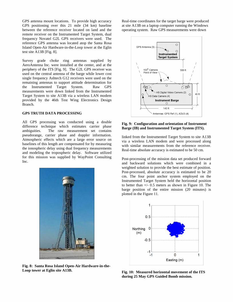
Real-time coordinates for the target barge were produced at site A13B on a laptop computer running the Windows operating system. Raw GPS measurements were down
Fig. 9: Configuration and orientation of Instrument Barge (IB) and Instrumented Target System (ITS). linked from the Instrumented Target System to site A13B via a wireless LAN modem and were processed along with similar measurements from the reference receiver. Real-time absolute accuracy is estimated to be 50 cm. Post-processing of the mission data set produced forward and backward solutions which were combined in a weighted solution to provide the best estimate of position. Post-processed, absolute accuracy is estimated to be 20 cm. The four point anchor system employed on the Instrumented Target System held the horizontal position to better than +/- 0.5 meters as shown in Figure 10. The barge position of the entire mission (20 minutes) is plotted in the Figure 11.
Fig. 10: Measured horizontal movement of the ITS during 25 May GPS Guided Bomb mission.

Post-process attitude determination was made possible by using the mission data set to compute the relative vector relationships between the three GPS antennas located on the Instrumented Target System. Fixed integer ambiguity determination enabled a better than 2 cm accuracy on the pitch and roll baselines which are 4.939 and 2.423 m
Fig. 11: Plot of horizontal and vertical ITS movement during 25 May GPS Guided Bomb mission. respectively. A classic theodolite survey of the Instrumented Target System antennas provided a one dimensional range constraint which allowed an estimate of GPS derived platform attitude accuracy. Software written in Matlab computed barge attitude estimates for pitch, heading and roll. These quantities are plotted for the last 1 minute of bomb flight in Figure 12. The estimated accuracy for pitch and heading is 0.23 degrees. The estimated accuracy for roll is 0.47 degrees.
Fig. 12: Plot of heading, pitch and roll of the ITS 1 minute prior to 25 May GPS Guided Bomb impact.
WEAPON SCORING RESULTS AT EGLIN TEST RANGE 12 March 2004 Operation − Laser Guided Bomb (LGB) Test Mission Following an initial checkout of the TARGT system pier side, the TARGT system was taken to sea and successfully deployed in just under 30 minutes in relatively calm (sea state 1-2) seas. Due to the limited (<5 nm) communications range experienced during an earlier operation in February (in which there was no weapon deployed), and with little time to troubleshoot the cause of the error prior to the 12 March test, the shipboard CCS was relocated to the Instrument Barge to ensure data collection. Prior to departing the test area it was noted that GPS and acoustic data was being successfully received by all six (6) of the TARGT AGS buoys, with only a few sporadic acoustic events noted by the system. The deployment pattern for the TARGT system during the test is depicted in Figure 13. Following the weapons release and impact, the support vessel returned to the OSDT test area and commenced AGS buoy recovery while the second TARGT operator transited to the Instrument Barge to recover the CCS. Upon recovery of the CCS, it was noted that a single real-time score was produced for the first weapon strike, but a real-time score was not produced for the second strike. It was also noted that two clear acoustic signatures were recorded onboard the CCS and on one of the AGS buoys – indicating the second weapon score could be produced. AGS buoy recovery was completed in approximately 80 minutes. The extended recovery time was due to one buoy dragging anchor due to increasing seas (sea state 4+). Following system recovery, it was noted that all AGS buoys performed well – with no leaks or physical damage experienced during the operation. It was further noted that a minor bug was present in the real-time scoring algorithm; that once corrected, allowed for generation of two real-time scores for the two events. Post-mission processing was performed by first computing a differential GPS C/A-code pseudo range solution between the NovAtel G2L GPS receiver located at the Eglin AFB Santa Rosa Island Open-Air Hardware-in-the-Loop tower, and each of the TARGT AGS buoy sensors. Using the GrafNav V7.0 post processing software developed by Waypoint Consulting, the DGPS pseudorange solution trajectory for each sonobuoy was used to identify a unique AGS buoy position for each impact event time. The real-time TARGT scoring software was then re-run to provide a refined post-mission score for each impact. The principal errors in this processing method are listed in Table 3.

Following generation and reporting of the post-mission score to the 46th Test Wing, the final score produced by the Instrumented Target System was provided to Trident Research. The ITS consisted of a precision time-tagged GPS target position and attitude determination subsystem
TARGT Buoy Locations - 12 March 2004 OSDT
0
5
10
15
20
25
30
35
40
20 25 30 35 40 45 50 55 60East Longitude (sec)
Nor
th L
atitu
de (s
ec)
Buoy 04
Buoy 07
Buoy 05
Buoy 06
Buoy 02
Buoy 03
InstrumentBarge
InstrumentedTarget System
Fig. 13: TARGT sensor deployment pattern for the 12 March 2004 operation LGB Test Mission. and target deck witness panels capturing the weapon impact location on the target. Table 5 lists the real-time and post-mission scores produced by TARGT, Table 6 lists the differences between the TARGT score and the instrumented target score, and Figure 14 depicts these differences graphically; assuming the Instrumented Target System score as truth (at the center of the plot). In both cases, the TARGT system performed as designed – with post-mission scores within 3.7 meters of truth. Detailed listings of the estimated error components that are included in this estimated post-mission scoring error are included in Table 4.
12 March 2004 Laser Guided Bomb Mission TARGTMiss Distances and Error Ellipses
-20
-15
-10
-5
0
5
10
15
20
-20 -15 -10 -5 0 5 10 15
Longitude Error (ft)
20
Latit
ide
Erro
r (ft
)
Miss DistanceFor Bomb 2 Relativeto GPS Truth
Miss DistanceFor Bomb 1 Relativeto GPS Truth
TruthCoordinates
Est 2D RMSError: +/-12.1 ft
Fig. 14: Graphical representation of TARGT miss-distances with estimated error ellipses.
The 12 March 2004 TARGT system test successfully demonstrated the ability to provide real-time and post-mission acoustic scores that were within the estimated errors predicted for the system in its original design. Further, software issues that were discovered during post-mission analysis were subsequently corrected, validated, and tested. 25 May 2004 Operation – GPS Guided Bomb The TARGT system was successfully deployed in support of this test mission utilizing the same CONOPS that was successfully deployed in the March test mission. However, prior to test mission day, a series of RF communications tests were performed to determine why the effective communications range of the TARGT system did not meet previously developed link budgets. Testing indicated RF interference with 900 MHz transmissions from a Yaggi directional antenna located on the Instrument Barge. Relocation of the TARGT antenna on the Instrument Barge, coupled with a 1 watt amplifier, provided communications ranges in excess of 10 nm (consistent with link budget estimates). In addition, a remote acoustic gain control capability was successfully tested at-sea on three of the six AGS buoys. This remote acoustic gain control feature allows the acoustic sensitivity of each TARGT buoy to be remotely set independently.
TARGT Buoy Coordinates - 25 May 2004 - OSDT Test
14.00
16.00
18.00
20.00
22.00
24.00
26.00
28.00
30.00
Nor
th L
atitu
de (s
ec)
10.00
12.00
25.00 30.00 35.00 40.00 45.00 50.00
West Longitude (sec)
Buoy 03
Buoy 07
Buoy 06
Buoy 02
Buoy 05
Buoy 04
Impact Event
Fig. 15: TARGT sensor deployment pattern for the 25 May 2004 GPS guided bomb test mission. Following an initial checkout of the TARGT system pier side, the TARGT system was taken to sea and successfully deployed in less than 30 minutes in very calm (sea state 1) seas. The deployment pattern for the TARGT system during the test is depicted in Figure 15. The precise location of the impact with the ITS was determined by measuring the bomb penetration on the witness panels of the platform [Fig. 16]. Following the weapon release and impact, the support vessel returned to the OTTA and commenced AGS buoy recovery while one

TARGT operator transited to the Instrument Barge to recover the CCS. Upon recovery of the CCS, it was noted that a single real-time score was produced for the weapon strike. The real-time score was immediately relayed to the Test Director and recorded. AGS buoy recovery was completed in approximately 45 minutes. Following system recovery, it was noted that all AGS buoys performed well – with no leaks or physical damage experienced during the operation. The 25 May GPS Guided Bomb test mission was the first test opportunity to prove out the time required to post-process a TARGT score since the software was modified after the March
Fig. 16: Location of 25 May 2004 bomb impact on ITS platform witness panels. 2004 test. Following strict data processing procedures, both the real-time score, produced within seconds after impact, and the post-mission score, produced within 24 hours after receipt of GPS reference station data, were performed without requiring any modifications to the TARGT software or processing procedures. It should noted that the score for the CORS reference station possesses an error ellipse slightly larger than that for the Eglin reference station score. This increased error
is due to a DGPS baseline between the CORS station and the impact area longer than the Eglin reference station to impact area baseline (approximately 74 and 34 km respectively). The real-time and post-mission scores produced by TARGT for the GPS Guided Bomb test mission are displayed in Table 7. In addition to utilizing the Eglin AFB reference station GPS data, Trident accessed the CORS data from the US Geological Survey (USGS) station at Pensacola, Florida and developed a score using this data as well. These results are also listed in Table 7. This was done to demonstrate the achievable performance of the TARGT system without reliance on the Eglin AFB ground station equipment. A comparison of the final TARGT score against the GPS derived truth coordinates are listed in Table 8 and depicted graphically in Figure 17. Note from Figure 17 that the estimated error ellipses for the score overlaps both the estimated truth coordinates provided by the 46th Test Wing and the targeting coordinates entered into the weapon.
25 May 2004 GPS Guided Bomb Mission
TARGT Miss Distances and Error Ellipses
-20
-15
-10
-5
0
5
10
15
20
-20 -15 -10 -5 0 5 10 15 20
Longitude Error (ft)
Latit
ude
Erro
r (ft
)
TruthCoordinates
Est 2D RMS Error: +/-12.1 ft
Miss DistanceRelative to
Bomb Coord
Miss DistanceRelative toGPS Truth
Fig. 17: TARGT post-mission miss distances with error ellipses for the 25 May 2004 GPS Guided Bomb Test Mission. The TARGT system successfully provided a real-time score that was within the estimated errors predicted for the system in its original design. The real-time score was available within seconds of the weapon impact (delayed due to time required to recover the CCS from the instrumentation barge). The exercise also successfully tested the remote audio gain control capability of the system, and pre-test day testing and analysis identified the RF communications interference source that had prevented effective TARGT communications in the preceding operations. Effective communications were demonstrated to 10+ nm; however, the TARGT CCS was located on the instrumentation barge as in the previous

operation to maintain configuration control over the system during the test. CONCLUSIONS Demonstrated Performance Comparison of TARGT weapon scores for tests conducted at the Eglin OTTA range with scores determined using the instrumented target method demonstrated the viability of using GPS acoustic buoys to assess weapon accuracy. The small size of the AGS buoys reduced logistical costs and minimized deployment and recovery time. TARGT performance is further enhanced by the use of COTS technology that reduced the cost and time required to develop the system. Pending Enhancements Sub-Meter Accuracy Scoring The current TARGT system is under modification to support sub-meter scoring requirements for precision weapons testing in the Eglin OTTA. The modification requires an upgraded OEM-GPS receiver capable of providing carrier phase data, and modification of onboard firmware to interface to the new receiver and to properly interpret and process the new measurements to the shipboard command and control system. The post-mission processing software is already capable of utilizing kinematic ambiguity resolution algorithms to provide fixing or floating the carrier phase ambiguities, allowing for accuracies of 20-40 cm in position for each AGS sensor, resulting in an estimated impact scoring accuracy of 60-70 cm CEP. Munition Recovery The capability to recover the deployed munition can prove useful during weapons testing operations. The ability to determine the location of the weapon on the bottom of the ocean can be accomplished by utilizing an impact area in shallow water (less than 300 ft), and by supplementing each AGS buoy with a secondary hydrophone and acoustic recording channel. The concept under investigation includes locating a secondary hydrophone approximately 30 ft above the sea floor. The acoustic signal from the secondary weapon impact on the bottom would be recorded and extracted in post-mission to determine impact time. Estimated bottom localization accuracies of 10-15 ft CEP are expected; well within the search range for recovery divers. Mammal Detection and Range Clearance The possible presence of marine mammals in an offshore test range creates a potential situation where endangered species can be harmed. One method to mitigate this harm is to identify the presence of marine mammals by the
sound they make [Au] and then use trilateration to determine their location [Ramaswamy]. Initial steps are being taken to modify the audio circuitry of TARGT to trigger on frequencies associated with marine mammals. An acoustic relay capability is also under development to allow the CCS operator to listen for mammal noises. TARGT listening and detection capabilities will provide test operators with the means of evaluating the range clearance of marine mammals. REFERENCES Au, Whitlow W.L; Popper, Arthur N.; Fay, Richard R., “Hearing by Whales and Dolphins” Springer-Verlag, 2000 Brekhovskikh, L.; Lysanov, Yu, “Fundamentals of Ocean Acoustics,” Springer-Verlag, 1982 Burdic, William S., “Underwater Acoustic System Analysis,” Prentice Hall, 2nd Edition, 1991 Cardoza, Miguel, et. al., “Autonomous Surface Watercraft”, US Patent 5119-09600, 11 February 2002. Eglin, “Final Programmatic Biological Assessment, Eglin Gulf Test and Training Range,” Eglin Air Force Base, Florida, November 2002 Etter, Paul, “Underwater Acoustical Modeling Principles, Techniques and Applications,” Elsevier Applied Science, 1991 Garnier, R.; Beltri, E.; Marchand, Ph. and Diner, N., “Noise Signature Management of Fisheries Research Vessels: A European Study,” European Conference on Underwater Acoustics, Elsevier Applied Science, 1992, p 210-215 Hamilton, Michael J., et al; “Acoustic Energy Attenuation of 3DVSP Airgun Arrays Operating in Long Beach Harbor,” IEEE Oceans Conference Record, Vol. 1, 2003, p 76-80 Ramaswamy, B.; Potty, G.R.; Miller, J.H., “A marine mammal acoustic detection and localization algorithm using spectrogram image correlation”, IEEE Oceans Conference Record, Vol. 4, 2001, p 2354-2358 Saunders, J. and Cardoza, M., “Preliminary Results from a GPS-Based Portable Impact Location System,” Proceedings of The Institute of Navigation’s Satellite Division Meeting, ION GPS-95, Palm Springs, CA, Sept., 1995, p 12-15 Wenz, Gordon M., “Acoustic Ambient Noise in the Ocean: Spectra and Sources,” The Journal of the Acoustical Society of America, Vol. 34, No. 12, Dec. 1962, p 1936-1956

Table 1. Relative Magnitude of Underwater Sound Sources
Source Level Reference Earthquake 65 to120 dB Wenz
66m Fishing Vessel 160 to 165 dB Garnier 53m Fishing Vessel 140 to 150 dB Garnier
Air Gun Array 236 dB Hamilton Blue Whale Moan 188 dB Au Grey Whale Moan 180 dB Au
Table 2. Ambient Ocean Noise Sources and Levels [Wenz].
Source Frequency Level Distant Shipping 10 – 200 Hz 60 – 85 dB
Sea State 6 200 – 2000 Hz 65 – 75 dB Sea State 1 200 – 2000 Hz 45 – 55 dB
Table 3: Principal Error Sources Associated With GPS Acoustic Scoring.
Error Source Description Approximate Magnitude
GPS Position Position of Buoy 7.0 m – no differential correction 0.6 m – phase & differential correction
Hydrophone Scope Displacement of Hydrophone Relative to GPS Antenna
1.0 m – drifting hydrophone 0.05 m – instrumented mast
Acoustical Timing Detecting Sound Arrival and Assigning Time Value
0.4 m – 8 kHz resolution 0.08 m – 40 kHz resolution
Estimated Total Root Mean Square 7.1 m – real time, low resolution 0.6 m – post-processed, high resolution
Table 4: Estimated Error Sources Associated With TARGT Post-Mission Scoring.
Error Source Description Approximate Magnitude
GPS Position Estimated Error in Computed
Differential GPS Position of Buoy Using C/A-code Data
0.50 m – est signal multipath at reference 1.50 m – est signal multipath at buoy 0.60 m – est reference receiver meas noise 2.24 m – est buoy C/A-code meas noise 0.05 m – reference coordinate uncertainty 1.28 m – satellite ephemeris baseline error 0.29 m – residual ionospheric error 0.52 m – est tropospheric baseline error 1.10 – estimated relative dilution of precision 3.65 m – estimated relative position error
Hydrophone Scope
Residual Error on Hydrophone Scope After Hydrophone Cantilever
Model Used to Account for Bias Due To Moored Buoys and Drifting
Hydrophone
0.50 m – residual drifting hydrophone error 0.05 m – instrumented mast offset
Acoustical Timing Detecting Sound Arrival and Assigning Time Value
0.40 m – 8 kHz resolution
Estimated Total Root Mean Square 3.71 m – total post-mission error

Table 5: Real-time and Post-processing TARGT Weapon Impact Scores for the Laser Guided
Bomb Test. Event Impact Time
(UTC) TARGT Lat
(N) TARGT Lon
(W) Estimated Error (ft)
2D RMS Real-time Score
Bomb 1 490226 30:03
21.24 086:34 30.72
23.2
Real-time Score Bomb 2
491140 30:03 21.60
086:34 31.44
23.2
Post-Mission Score Bomb 1
490226.01 30:03 21.276432
086:34 30.815256
12.1
Post-Mission Score Bomb 2
491139.99 30:03 21.493080
086:34 30.9109440
12.1
Table 6: Differences Between TARGT and Truth for the Laser Guided Bomb Test.
Event TARGT Lat (N)
TARGT Lon (W)
Truth Lat (N)
Truth Lon (W)
Lat Diff (ft)
Lon Diff (ft)
Bomb 1 30:03 21.276432
086:34 30.815256
30.03: 21.358058
086:34: 30.912103
-8.24 -9.78
Bomb 2 30:03 21.493080
086:34 30.9109440
30.03: 21.606898
086:34: 30.896098
-2.61 1.50
Table 7: Real-time and Post-Mission TARGT Scores for the GPS Guided Bomb Test.
Event Impact Time (UTC)
TARGT Lat (N)
TARGT Lon (W)
Estimated 2D RMS Error (ft)
Real-time 233020.31 30:03 21.426768
086:34 38.564148
23.2
Post-mission – Eglin Reference Station
233020.31 30:03 21.572856
086:34 38.451900
12.1
Post-mission – CORS Reference Station
233020.31 30:03 21.540744
086:34 38.433072
15.3
Table 8: Differences Between TARGT and Truth for the GPS Guided Bomb Test.
Event TARGT Lat (N)
TARGT Lon (W)
Truth Lat (N)
Truth Lon (W)
Lat Diff (ft)
Lon Diff (ft)
Bomb 1 30:03 21.56544
086:34 38.26838
30.03: 21.524101
086:34: 38.194895
4.18 7.42