wearable textile elongation sensor - upirf/proceedings_irf2016/data/papers/6223.pdf · fig. 4 -...
TRANSCRIPT

Proceedings of the 5th International Conference on Integrity-Reliability-Failure, Porto/Portugal 24-28 July 2016
Editors J.F. Silva Gomes and S.A. Meguid
Publ. INEGI/FEUP (2016)
-271-
PAPER REF: 6223
WEARABLE TEXTILE ELONGATION SENSOR
Carlos Gonçalves1(*)
, Alexandre Ferreira da Silva2, Ricardo Simoes
3,4
1Center of Nanotechnology and Smart Materials (CENTI), Famalicão, Portugal 2Center for Microelectronical Systems, University of Minho, Guimarães, Portugal 3Institute for Polymers and Composites IPC/I3N, University of Minho, Guimarães, Portugal 4Polytechnic Institute of Cávado and Ave, Barcelos, Portugal (*)Email: [email protected]
ABSTRACT
This work shows a developed wearable elongation sensor based on an optical fiber. The
presented approach to sew a fiber optic into a lycra textile enables the modulation of light
amplitude in respect to textile strain. This apparatus in combination with small-size
instrumentation enables the development of a wearable textile garment capable of monitoring
and acquiring strain data, and send it wirelessly to a base station. The light amplitude
increases with the increment of textile strain. The output voltage remains stable over time for
the resting and maximum textile strain position.
Keywords: Wearable applications, fiber optic sensors, elongation sensor.
INTRODUCTION
In this paper it is reported the design and fabrication of a wearable elongation sensor based on
optical fibers. The optical fiber is sewed on the top of a lycra textile surface. This kind of
sensors can be used for posture and motion analysis in sports, medicine and rehabilitation.
The unique properties of an optical fiber contribute to enhance the performance of elongation
sensors making them capable of providing reliable solutions for those applications where
conventional sensors are not suitable. Glass optical fibers have some good properties, such as
lightweight, small diameter and no threat of electrical risk [1]. A typical single mode fiber
(SMF) has an outer diameter of only 125 µm (62 µm inner core more cladding). Additional
protective layers will increase dimensions, up to 900 µm for the outer diameter. Glass optical
fibers are made of SiO2 with a density (2200 kg m-3) approximately four times lighter than
copper, which also facilitates miniaturization [2, 3].
The geometrical versatility of optical fibers allows them to bend in textiles to diameters of
10 mm, which make them suitable to adapt to complex surfaces, such as skin surfaces and
body joints [4]. They also offer an excellent measurand-type range and can be used as a
generic sensing element to quantify other physical quantities such as force, acceleration,
pressure, vibration, electromagnetic field and certain chemical quantities [5-7].
During the past few years many successful attempts have been done in order to integrate
optical fibers into wearable textiles. Dunne et al. developed a wearable plastic optical fiber
(POF) sensor for monitoring seated spinal posture [8]. Li et al. developed a novel wearable
sensor for human body temperature measurement, with the goal of integrate optical Fiber
Bragg Grating (FBG)-based sensors into functional textiles, extending the capabilities of
wearable solutions for body temperature monitoring [9]. Fujiwara et al. developed a glove-

Topic_D: Composite and Advanced Materials
-272-
based sensor using flexible optical fiber microbending transducers for applications in
biomechatronics. The devices are attached onto the dorsal surface of monitored joint, which
detects variations of ~4° in angular displacements [10].
In this paper it is possible to read a short description of the developed elongation sensor. The
hardware/software needed to operate the sensor is also reported. The results describe how the
test was performed and discuss the plots from the elongation tests. Final section in this paper
is a conclusion about the elongation sensor where the results and possible applications are
synthetize.
SENSOR DESCRIPTION
The elongation sensor is made of a single mode optical fiber (ø = 900 µm) sewn into a lycra
textile in a double wave shape as shown in figure 1. SC fiber optic connectors are used for
pass light through the optical fiber. Those connectors were chosen due to their small
dimensions that make easier textile integration. One connector connects with a photodetector
and the other end connects with a light emitter. The optical fiber is sewn into 22 wave shapes,
with a maximum diameter of 1.2 cm, which together decrease the resting sensed voltage in
the photodetector down to 1.5 V after amplification. At the same time the wave shapes and
diameter allow to increase the sensed voltage up to 1.9 V after amplification when the sensor
is stretched. Decreasing the optical fiber wave diameter can damage the optical fiber, which
will stop or decrease the amount of light passing through. Increasing the number of waves
will also decrease the amount of light passing through the fiber.
Fig. 1 - Elongation sensor.
HARDWARE
The fiber optic connectors couple with the light emitter and a photo detector. When the lycra
is stretched, the light amplitude passing thought the fiber increases, which increases the
output voltage coming out the photodetector. The output voltage from the photodetector was
amplified and then digitalized from the analog to digital converter (ADC) of the
microcontroller. The digital value was sent to a computer by Bluetooth connection. The
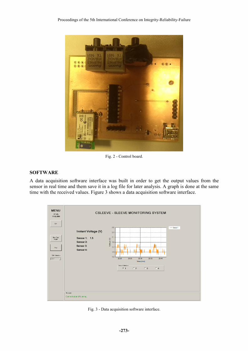
sampling ratio was 1 Hz. Figure 2 shows the printed circuit board (PCB) where the fiber optic
connectors are plugged. The circuit can be powered by a battery or plugged into a 5 V power
supply.
Proceedings of the 5th International Conference on Integrity-Reliability-Failure
-273-
Fig. 2 - Control board.
SOFTWARE
A data acquisition software interface was built in order to get the output values from the
sensor in real time and them save it in a log file for later analysis. A graph is done at the same
time with the received values. Figure 3 shows a data acquisition software interface.
Fig. 3 - Data acquisition software interface.
Topic_D: Composite and Advanced Materials
-274-
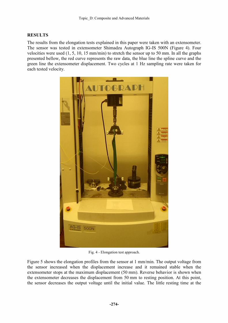
RESULTS
The results from the elongation tests explained in this paper were taken with an extensometer.
The sensor was tested in extensometer Shimadzu Autograph IG-IS 500N (Figure 4). Four
velocities were used (1, 5, 10, 15 mm/min) to stretch the sensor up to 50 mm. In all the graphs
presented bellow, the red curve represents the raw data, the blue line the spline curve and the
green line the extensometer displacement. Two cycles at 1 Hz sampling rate were taken for
each tested velocity.
Fig. 4 - Elongation test approach.
Figure 5 shows the elongation profiles from the sensor at 1 mm/min. The output voltage from
the sensor increased when the displacement increase and it remained stable when the
extensometer stops at the maximum displacement (50 mm). Reverse behavior is shown when
the extensometer decreases the displacement from 50 mm to resting position. At this point,
the sensor decreases the output voltage until the initial value. The little resting time at the

Proceedings of the 5th International Conference on Integrity-Reliability-Failure
-275-
maximum extension and resting point justify the curve sloop shape. Similar behavior is
presented in the second cycle.
Fig. 5 - Elongation profile at 1 mm min-1
Figure 6 shows the elongation profiles from the sensor at 5 mm/min. The output voltage from
the sensor increased when the displacement increase. No resting time was set for this
experiment, which justify the sloop peaks in the graph. The absolute gradient sloops are the
same for the stretching and de-stretching sensor. For the stretching, there is a positive gradient
sloop and for the de-stretching the gradient sloop is negative. Similar behavior is shown in
both cycles.
Fig. 6 - Elongation profile at 5 mm min-1

Topic_D: Composite and Advanced Materials
-276-
Figure 7 shows the elongation profiles from the sensor at 10 mm/min. Comparing the results
performed at 5 and 10 mm/min, the main difference is the absolute gradient sloops. As
expected the absolute gradient sloop is higher for the higher velocity. The absolute gradient
sloops are the same for the stretching and de-stretching sensor. For the stretching there is a
positive gradient sloop and for the de-stretching the gradient sloop is negative. Once again, no
resting time was set, which justify the peaks. Similar behavior is shown in both cycles.
Fig. 7 - Elongation profile at 10 mm min-1
Figure 8 shows the elongation profiles from the sensor at 15 mm/min. The square shape seen
in the graph can be justify due to the short time needed to reach 50 mm elongation and the
longer resting time. Once again, when the sensor reaches the 50 mm extension, the output
voltage remains stable and the same behavior is noticed when the sensor returns to the resting
position. Similar behavior is presented in the second cycle.
Fig. 8 - Elongation profile at 15 mm min-1

Proceedings of the 5th International Conference on Integrity-Reliability-Failure
-277-
CONCLUSION
With the performed work to this paper it is possible to prove that optical fibers can be
embedded into wearable textiles in order to measure displacements induced by applied forces
into the textiles. The results show a direct correlation between the sensor displacement and
the output voltage sensed in the optical sensor. In all the performed tests the sensor increase
the output voltage when the displacement increase. The same output voltage at resting
position and maximum displacement (50 mm) it is always verified remaining stable over time.
With the collected data it is possible to calculate a sensibility of 1 mm and a resolution of 8
mV/mm. This work can be applied in the field of compression garments for sports and
healthcare, enabling the sensing of an active compression control in real time.
ACKNOWLEDGMENTS
This work is funded by FEDER funds through the COMPETE 2020 Programme and National
Funds through FCT - Portuguese Foundation for Science and Technology under the project
UID/CTM/50025/2013, and the PhD grant SFRH/BD/52352/2013. We also acknowledge
support from CeNTI – Centre for Nanotechnology and Smart Materials.
REFERENCES
[1]-Roriz, P., et al., Review of fiber-optic pressure sensors for biomedical and biomechanical
applications. Journal of biomedical optics, 2013. 18(5): p. 050903-050903.
[2]-Xu, J., High temperature high bandwidth fiber optic pressure sensors. 2005, Virginia
Polytechnic Institute and State University.
[3]-Miller, S., Optical fiber telecommunications. 2012: Elsevier.
[4]-Mohanty, L., et al., Fiber grating sensor for pressure mapping during total knee
arthroplasty. Sensors and Actuators A: Physical, 2007. 135(2): p. 323-328.
[5]-Dennison, C.R. and P.M. Wild, Enhanced sensitivity of an in-fibre Bragg grating pressure
sensor achieved through fibre diameter reduction. Measurement Science and Technology,
2008. 19(12): p. 125301.
[6]-Yeh, C., Handbook of fiber optics: theory and applications. 2013: Academic Press.
[7]-Grattan, L. and B. Meggitt, Optical fiber sensor technology: advanced applications-Bragg
gratings and distributed sensors. 2013: Springer Science & Business Media.
[8]-Dunne, L.E., et al. Design and evaluation of a wearable optical sensor for monitoring
seated spinal posture. in Wearable Computers, 2006 10th IEEE International Symposium on.
2006. IEEE.

Topic_D: Composite and Advanced Materials
-278-
[9]-Li, H., et al., Wearable sensors in intelligent clothing for measuring human body
temperature based on optical fiber Bragg grating. Optics express, 2012. 20(11): p. 11740-
11752.
[10]-Fujiwara, E., et al. Design of a glove-based optical fiber sensor for applications in
biomechatronics. in Biomedical Robotics and Biomechatronics (2014 5th IEEE RAS &
EMBS International Conference on. 2014. IEEE.