web-based wireless sensor network platform
TRANSCRIPT

WEB-BASED WIRELESS SENSOR
NETWORK PLATFORM
Pérez Cano, José Antonio
Academic course 2014-2015
Supervisor: Gabriel Martins
BACHELOR’S DEGREE IN AUDIOVISUAL SYSTEMS ENGINEERING
Final Degree Project
GRAU EN ENGINYERIA EN
xxxxxxxxxxxx


WEB-BASED WIRELESS SENSOR NETWORK
PLATFORM
José Antonio Pérez Cano
FINAL DEGREE PROJECT
Bachelor’s degree in Audiovisual Systems Engineering
Polytechnic School – Pompeu Fabra University
2015
Supervisor
Gabriel Martins Dias


iii
Dedicado a mi familia y amigos.


v
Acknowledgement
I would like to specially thank my family and friends for supporting me during these
recent years of my life, and my supervisors, Toni Adame and Gabriel Martins, for
helping me in the development of this project.


vii
Abstract
The aim of this project is to design and implement a web-based platform for storing and
visualizing the data retrieved by Wireless Sensor Networks (WSNs). This approach is
part of the Entomatic project, an European Union (EU) funded plan for addressing a
major problem faced by EU Associations of Olive growing Small and Medium-sized
Enterprises (SMEs): the Olive fruit fly (Bactrocera oleae). Olive oil trees will feature a
series of sensors, mainly consisting of olive fly traps as a way to track its population.
Such sensors will output data through a gateway to be finally gathered by the platform
proposed in this document. The system presented in this project consists of two parts:
(1) a web-server that receives the sensed data and stores them in a database; and (2) a
web-application for visualizing the obtained measurements including, among others,
map node location, statistics, and charts. Cutting edge web technologies have been used
in order to create a modern, yet maintainable and scalable platform.
Resumen
El objetivo de este proyecto es diseñar e implementar una plataforma web para
gestionar una red de sensores inalámbrica (WSN). Esta propuesta es parte del proyecto
Entomatic, un plan financiado con fondos de la Unión Europea (UE) para solucionar un
problema creciente en las pequeñas y medianas empresas (Pymes) de cultivo de aceite
de oliva: la mosca del Olivo (Bactrocera oleae). Diferentes tipos de sensores,
principalmente trampas para moscas, serán colocados en los olivos como manera de
controlar la población. Estos sensores generarán datos a través de una puerta de enlace
(Gateway) para finalmente ser obtenidos por la plataforma propuesta en este
documento. El sistema presentado en este proyecto consiste de dos partes: (1) un
servidor web que recibe los datos obtenidos por los sensores y los almacena en una base
de datos; y (2) una aplicación web para visualizar las medidas obtenidas, incluyendo,
entre otros, localización de nodos en mapa, estadísticas, y gráficos. Tecnologías de
estado del arte se han usado con la finalidad de crear un plataforma moderna,
mantenible y escalable.


ix
Index
Page
Abstract.......................................................................... vii
1.INTRODUCTION……………………….................. 1
1.1 Project overview......................................................
1.2 Entomatic Project………………………………….
1.1.2 Internet of the things (IoT)………………………
1.2.2 Wireless Sensor Networks (WSN)………………
1.2.3 Cloud Computing………………………………..
1.2.4 Problem to be solved…………………………….
1.2.5 Motivation……………………………………….
1.2.6 Scope of the proposed project…………………...
1.2.7 Project planning…………………………………
1
2
3
3
4
4
5
5
6
2. STATE OF THE ART……………………………... 7
2.1 Existing WSN platforms.........................................
2.2 Web technologies………………………………….
2.2.1 Web architecture………………………………...
2.2.1.1 Client-server model……………………………
2.2.1.2 N-tier architecture……………………………..
2.2.1.3 Uniform Resource Locators (URL)…………...
2.2.1.4 HTTP protocol………………………………..
2.2.1.5 Messaging formats…………………………….
2.2.1.6 Representational State Transfer……………….
2.2.1.7 Web applications………………………………
2.3 Web frameworks…………………………………..
2.3.1 Backend frameworks…………………………….
2.3.1.1 Architectural patters –MVC…………………...
2.3.1.2 Programming languages……………………….
2.3.1.3 Software design style………………………….
2.3.1.4 Object-relational mapping (ORM)…………….
2.3.1.5 Restful APIs…………………………………...
2.3.1.6 Considered platforms………………………….
2.3.2 Frontend Frameworks…………………………...
2.3.2.1 Single page applications………………………
2.3.2.2 Asynchronous JavaScript And XML (AJAX)...
2.3.2.3 JavaScript frameworks………………………..
2.3.2.4 CSS frameworks………………………………
2.3.3 Data Base Engines………………………………
2.3.3.1 Relational Data bases (SQL)…………………..
2.3.3.2 No SQL DB……………………………………
2.4 Code versioning…………………………………...
3. USED TECHNOLOGIES…………………………..
3.1 Server side framework…………………………….
3.2 Front End frameworks…………………………….
7
7
8
9
9
10
10
11
11
11
12
12
12
14
15
15
16
17
19
20
20
20
23
23
23
23
23
25
25
26

x
3.3 Data Base engine…………………………………..
3.4 Versioning…………………………………………
27
27
4. PLATFORM IMPLEMENTATION……………......
4.1 Design Strategy……………………………………
4.1.1 Design constraints……………………………….
4.1.2 Proposed design…………………………………
4.2 Database…………………………………………...
4.2.1 Requirements……………………………………
4.2.2 Data model………………………………………
4.3 Sails.js Backend…………………………………...
4.3.1 Project structure…………………………………
4.3.2 WSN API………………………………………..
4.3.2.1 New gateway………………………………….
4.3.2.2 New Sensor……………………………………
4.3.2.3 New Measurement…………………………….
4.3.2.4 New Alarm…………………………………….
4.3.3 Web app API…………………………………….
4.3.3.1 Page Controller………………………………..
4.4 Front End…………………………………………..
4.4.1 Angular.js app components……………………...
4.4.2 Login module……………………………………
4.4.2.1 User authentication……………………………
4.4.3 Dashboard module (main module)………………
4.4.3.1 CSS components………………………………
4.4.3.2 UI routing……………………………………...
4.4.3.4 Main…………………………………………...
4.4.3.5 Home…………………………………………..
4.4.3.6 Sensor Location……………………………….
4.4.3.7 Statistics……………………………………….
4.4.3.8 Alarms…………………………………………
4.4.3.9 Configurations…………………………………
4.5 Version control…………………………………….
5. WEB APPLICATION WALKTHROUGH………...
5.1 Login………………………………………………
5.2. Dashboard………………………………………...
5.2.1 Top Navigation bar……………………………...
5.2.2 Lateral navigation bar…………………………...
5.2.3 Home…………………………………………….
5.2.4 Sensor location…………………………………..
5.2.5 Statistics…………………………………………
5.2.6 Alarms…………………………………………...
5.2.7 Configurations…………………………………...
29
29
29
29
30
31
31
35
35
37
38
39
41
44
46
46
47
47
48
48
49
49
49
52
53
53
54
54
55
55
57
57
58
59
59
60
61
64
66
66
6. DEPLOYMENT AND TESTING……………….....
6.1 Deployment………………………………………..
6.2 Testing scenario…………………………………...
6.2.1 Measurement types……………………………...
69
69
69
70

xi
6.2.2 WSN Hardware………………………………….
6.2.3 WSN simulation results………………………....
7. CONCLUSIONS……………………………………
7.1 Future Work……………………………………….
Bibliography…………………………………………...
70
73
77
77
79

xii

1
Chapter 1: Introduction
1.1 Project overview
During the last decade, sensors have become part of our lives. We use them constantly:
in our smartphones, factories tracking CO2 emissions, heart monitoring implants, etc.
Even the most unimaginable things can be sensed and tracked. In that sense, the
reduction of manufacturing costs and the technological development of these devices
have led to the spread of the phenomena of the Internet of things (IoT), a scenario in
which objects, animals or people are provided with unique identifiers and the ability to
transfer data over a network without requiring human interaction [1].
Moreover, the use of Wireless Sensor Networks (WSN) has made possible many IoT
scenarios by the use of wireless distributed independent devices (within a network) that
use sensors to monitor physical conditions, and therefore, making it easier in for certain
applications that need the use of this technology [2].
Many interesting applications can be derived from these concepts including wide areas
such as health and sports, military and defense or industrial use. The data generated
from the sensors in these projects can be huge and any sort of managing platform is
needed for storing, visualizing and manipulating the output. The use of graphical
interfaces (GUI) with desktop or web applications combined with servers and data bases
(DB) are a common way to solve this issue by providing user friendly access to data.
This project proposes, designs and implements a web platform for storing and
visualizing the data retrieved by WSNs. This approach is part of the Entomatic Project,
a European funded plan for tracking the olive fruit fly population. The system will be in
charge of (1) obtaining and storing the data gathered by a WSN and (2) a web-
application for visualizing the obtained measurements including, among others, map
node location, statistics, and charts. Fig 1 shows an approximation of the system that is
presented.

2
Fig. 1.1: The presented system
1.2 Entomatic Project
This section will provide information regarding the project in which the platform is
framed.
The Entomatic project is a European for addressing a major problem faced by EU
Associations of Olive growing Small and Medium-sized Enterprises (SMEs): the Olive
fruit fly (Bactrocera oleae). This insect pest causes yearly economic losses estimated to
be almost €600/ha. ENTOMATIC aims to develop a novel stand-alone field monitoring
system comprising: a fully autonomous trap with integrated insect bioacoustic
recognition embedded in a wireless sensor network and supported by a spatial decision
support system. Olive producers will be able to track pest population and geographical
status and receive advice on precision pesticide application. [3]
The architecture of the Entomatic project can be summarized in two parts: the WSN
where sensors are placed and obtains the information, and the cloud platform for storing
the data and managing the platform (where this project takes part).

3
Fig. 1.2: The Entomatic Architecture
1.2.1 Internet of things (IoT)
This project should be considered as part of the Internet of things (IoT). The Internet of
things can be defined as “[..] A scenario in which objects, animals or people are
provided with unique identifiers and the ability to transfer data over a network without
requiring human-to-human or human-to-computer interaction.” [1]. In this sense,
Entomatic is providing a series of sensors meant for tracking the population of the olive
oil fruit fly and thus making use of the IoT paradigm
1.2.2 Wireless Sensor Networks (WSN)
The whole Entomatic project relies on the WSN technology. In a WSN, wireless sensor
nodes are spatially distributed autonomous sensors to monitor physical or
environmental conditions, such as temperature, sound, pressure, etc., and to
Database
IPM SoftwareWeb Map
ServerPC
PC
MobilePhone
Tablet
ONLINE ACCESSWeb-Access
Data Receiver Server
OFFLINE ACCESSStand-Alone Aplication
Gateway
Traps + Wireless modules
Internet
Olive tree
GPRS, GSM,
Satellite-Internet
USB, RS-232
IEEE 802.15.4 (Zigbee),IEEE 802.11 (WLAN)
ENTOMATIC Cloud Architecture
Monitoring & Management Central
GIS (Geographic Information System)
GUI (Graphical User Interface)
IPM SOFTWARE(Integrated Pest Management Software)
Regional & national authorities
Organizations from a specific region
Single SME-AG
LEVELS OF DATA ACCESS

4
cooperatively pass their data through the network to a main location [2]. Entomatic is
designed to feature two keys elements of a WSN:
Wireless sensor nodes, such as the olive fruit fly traps, acting as end points.
One or more gateways which transmit (as well as manage) all the nodes data to
an external server.
Fig. 1.3: Entomatic WSN
1.2.3 Cloud computing
Cloud computing is a paradigm in which computing services can be done through the
internet [4]. Entomatic project relies over this term as all data coming from the different
olive trees fields will be stored over a cloud platform, physically located away from
where the data was acquired, and therefore relying on an internet resource. It is
important to focus on this fact as the prototype proposed in this work will act as an early
stage cloud cloud platform for Entomatic.
1.2.4 Problem to be solved
The problem to be solved relies on creating the cloud or web platform for the WSN. In
its final form, this platform should provide a solution for SMEs to track their Olive tree
fields and obtain meaningful data so as to increase their productivity. This will include,
storing in a proper way all the data coming from the sensors; and a web application for
showing the data regarding the obtained measurements, and the location of the nodes.
Although the market provides a wide variety of tools for developing web platform,

5
research has been carried in order to show the current state of the art technologies as
well providing with a scalable and maintainable system.
1.2.5 Motivation
The main motivation for carrying out this project was to be involved in a real project as
my final degree work and to contribute to something meaningful.
Having been a developer in a consulting company for almost a year was also an extra
motivation as to expand my knowledge into new technologies and to apply into a
personal project the learned concepts.
1.2.6 Scope of the proposed system
The platform or system to be implemented should have to following specifications:
Feature a Restful API for managing a WSN which should store the following
information:
o Gateway: The system should be able to store and sync with any gateway
from the WSN.
o Nodes: The platform should be capable of storing nodes and to
synchronize with them.
o Measurements: Store the different measurements the sensors output such
as temperature, relative humidity among others.
o Alarms: Handle alarms from the WSN (as way to notify if any problems
happen in the network) and create any other if issues occur.
Web Application to visualize data including the following features:
o Provide a user authentication tool.
o Map nodes and gateways location.
o Manage different measurements from the sensors, and filter and sort
them by different date periods.
o Alarm handling as a way of managing the possible issues that the WSN
may face.
6
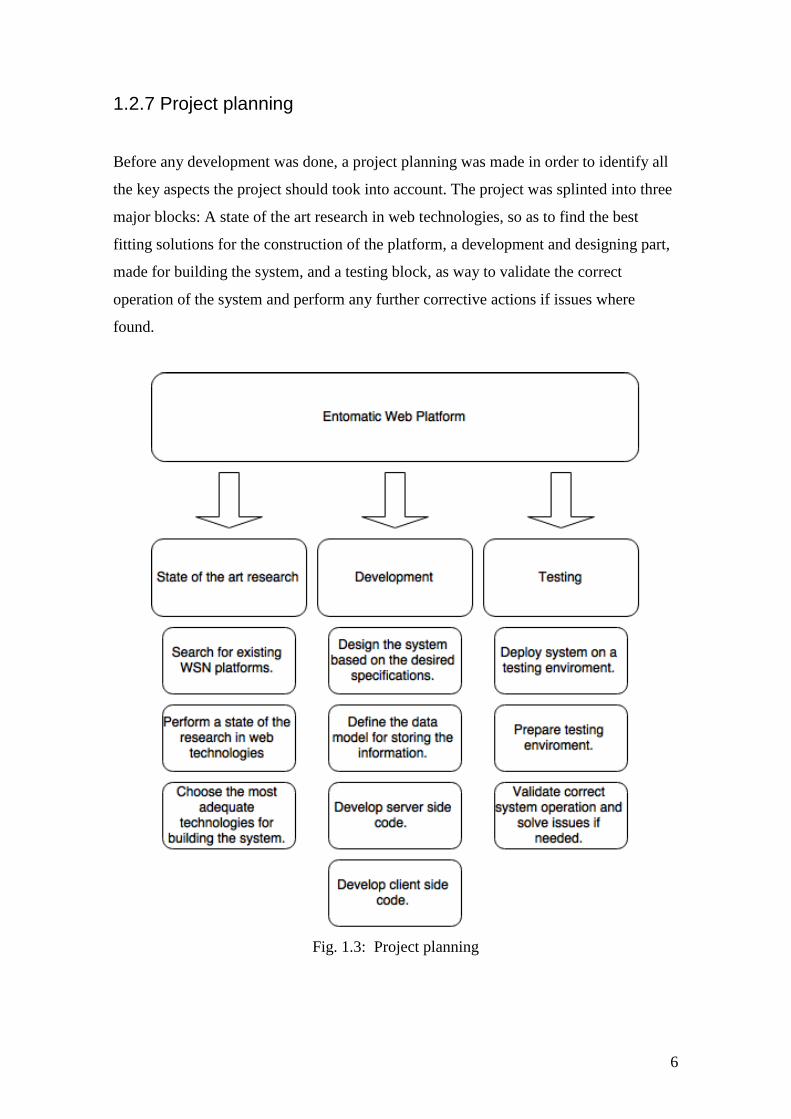
1.2.7 Project planning
Before any development was done, a project planning was made in order to identify all
the key aspects the project should took into account. The project was splinted into three
major blocks: A state of the art research in web technologies, so as to find the best
fitting solutions for the construction of the platform, a development and designing part,
made for building the system, and a testing block, as way to validate the correct
operation of the system and perform any further corrective actions if issues where
found.
Fig. 1.3: Project planning
7
Chapter 2: State of the art
This chapter will feature the current state of the art as far as web technologies for
developing modern web platforms are concerned as well as giving brief information
about the existing platforms for managing WSNs.
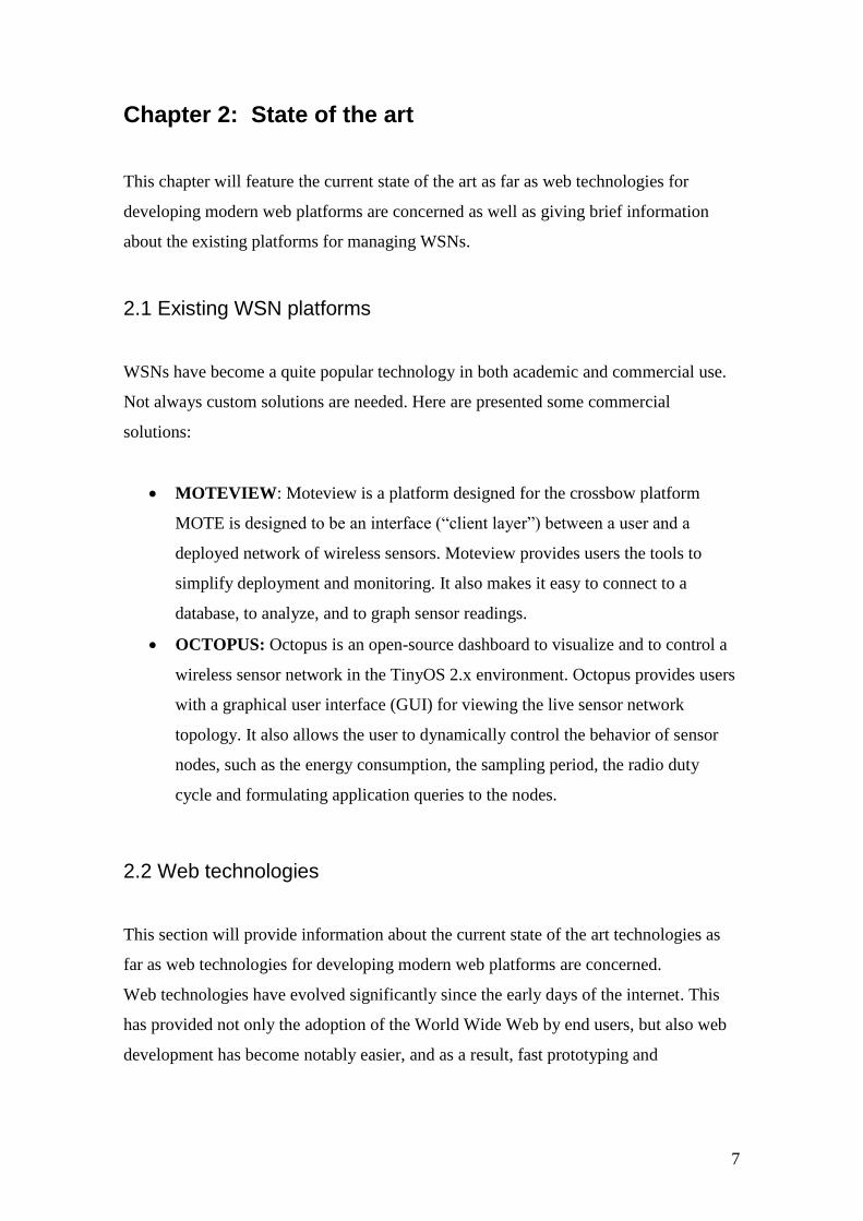
2.1 Existing WSN platforms
WSNs have become a quite popular technology in both academic and commercial use.
Not always custom solutions are needed. Here are presented some commercial
solutions:
MOTEVIEW: Moteview is a platform designed for the crossbow platform
MOTE is designed to be an interface (“client layer”) between a user and a
deployed network of wireless sensors. Moteview provides users the tools to
simplify deployment and monitoring. It also makes it easy to connect to a
database, to analyze, and to graph sensor readings.
OCTOPUS: Octopus is an open-source dashboard to visualize and to control a
wireless sensor network in the TinyOS 2.x environment. Octopus provides users
with a graphical user interface (GUI) for viewing the live sensor network
topology. It also allows the user to dynamically control the behavior of sensor
nodes, such as the energy consumption, the sampling period, the radio duty
cycle and formulating application queries to the nodes.
2.2 Web technologies
This section will provide information about the current state of the art technologies as
far as web technologies for developing modern web platforms are concerned.
Web technologies have evolved significantly since the early days of the internet. This
has provided not only the adoption of the World Wide Web by end users, but also web
development has become notably easier, and as a result, fast prototyping and

8
implementation of web applications, like the one proposed in this work, could be made
possible.
In order to introduce the reader the different solutions available, prior explanations will
be carried about core concepts regard how web platforms are designed followed by
more specific technology point of view implementations of the available technologies.
2.2.1 Web architecture
A web architecture represents how a network enabled system is designed from a high
level perspective. Figure 2.1 shows an approximation of how the proposed web
architecture should look like from web architecture perspective.
Fig. 2.1: Resume of the proposed web architecture

9
2.2.1.1 Client-server model
The client-server model is the de-facto way of how web-enabled systems work. The
application proposed in this document will feature this model. This type of distributed
computing model splits the tasks or workloads between the providers of a resource or
service, called servers, and service requesters, called clients [5].
In the proposed web-application there will be the following distinction:
Clients:
Data coming from the WSNs (sensors placed in the olive trees).
Web explorer (i.e. Chrome, Firefox etc.) requesting for the web-application for
visualizing and managing the WSN data.
Server:
Web-server in charge of gathering the data and serving the web-application.
Data base server for storing the WSNs information as well as other web
application related information.
2.2.1.2 N-tier architecture
In addition to the client-server model, further divisions can be done. Typical web
architectures will feature the n-tier or multi-tier architectures, usually consisting of 3 or
4 tiers, which can be listed as:
Client tier: Usually consisting of a web applications or client end points.
Application tier: The web server and the app server (which can be sometimes
split) that accepts the requests from the clients and performs the business logic.
Data tier: The data layer provides access to external systems such as a data
base. Databases provide a solution for persisting data and for managing all the
related transitions.

10
Fig. 2.2: Example 3-tier architecture
2.2.1.3 Uniform Resource Locators (URL)
A uniform resource locator (URL) is a reference to a resource that specifies the location
of the resource on a computer network and a mechanism for retrieving it [6]. URLs are
the standard way web browsers and in general any connected device to the internet uses
for obtaining a result.
2.2.1.4 HTTP Protocol
In order to provide with an application protocol for exchanging data between clients and
server, HTTP is the standard protocol for this purpose. The HTTP protocol is based on a
request-response model. The client requests data from a web application that resides on
a physical machine. The web application in turn responds to the request with the data
requested by the user. [7]
The HTTP protocol contains a series or methods (or verbs) meant for the different types
of requests the client can send, which in turn represent different intentions on the client
side. The main methods are:
GET: For accessing data.
POST: For submitting data.
11
PUT: For updating existing data.
DELETE: For deleting resources.
2.2.1.5 Messaging formats
The most used formats of messaging using the HTTP protocol are the following:
XML: Extensible Markup Language (XML) is a markup language that defines a
set of rules for encoding documents in a format which is both human-readable
and machine-readable.
JSON: JavaScript Object Notation (JSON) is an open standard format that uses
human-readable text to transmit data objects consisting of attribute–value pairs.
It is used primarily to transmit data between a server and web application, as an
alternative to XML.
2.2.1.6 Representational State Transfer (Rest)
Representational State Transfer (Rest) defines a set of architectural principles by which
Web services can be designed that focus on a system's resources, including how
resource states are addressed and transferred over HTTP by a wide range of clients
written in different languages [8]. Rest defines 4 basic rules:
The basic use of HTTP methods explicitly.
Stateless, meaning the server never stores a state from any client.
Expose directory structure-like URLs.
Transfer XML, JavaScript Object Notation (JSON), or both.
Most modern web systems use this approach as the standard way of communication
between clients and server.
2.2.1.7 Web applications
A web application is a software that runs in a web-browser, and therefore, relies on a
web-server for serving the data [14]. A general web page or application is
composed of the following elements:

12
HTML code: The html code defines the elements in a webpage. Version 5
CSS Style Sheet: The CSS is the style that will be applied to the webpage.
JavaScript: Expands the functionality of the basic HTML features by applying
an underneath logic beneath it.
2.3 Web frameworks
A web application framework is a type of framework, or foundation, specifically
designed to help developers build web applications. These frameworks typically
provide core functionality common to most web applications, such as user session
management, data persistence, and templating systems. By using an appropriate
framework, a developer can often save a significant amount of time building a web
application[9].
By following this definition, the main reason for using a framework will be time
constraints and for available documentation, which will enable developing features with
better ease.
There are several frameworks available, but in this project I will consider the most
active ones as having a proven trajectory of being successful in production
environments.
2.3.1 Backend frameworks
Backend frameworks are the frameworks that reside on the server side of the
application, and are responsible for accepting the HTTP requests and communicating
with the data base servers (application tier). Different framework types can vary
significantly depending on the purpose of their usage; whether they are enterprise
oriented (robust and reliable platforms) or more prototype-oriented such as start-up
companies.
2.3.1.1 Architectural software Patterns - MVC
Software architecture refers to how a software is structured from a high level point of
view. In an analogous way, it could be considered as an equivalent of the architecture of
a building. There are many ways of describing the type of software architecture, but
13
because of the scope of this paper, only the de-facto industry standard for web
applications will be explained.
Model–view–controller (MVC) is one of the most popular software architecture
patterns. This pattern, intended for implementing interfaces, divides the software into
three interconnected layers as way to separate internal representations from what the
user should see [9].
Keys components of this pattern are:
• Models: Models represent knowledge. A model could be a single object or it could be
some structure of objects. For instance, a model could represent a data base table.
• Views: A view is a (visual) representation of its model. It would ordinarily highlight
certain attributes of the model and suppress others. It is thus acting as a presentation
filter. A view is attached to its model (or model part) and gets the data necessary for the
presentation from the model by asking questions.
• Controllers A controller is the link between a user and the system. It provides the user
with input by arranging for relevant views to present themselves in appropriate places
on the screen. It provides means for user output by presenting the user with menus or
other means of giving commands and data. The controller receives such user output,
translates it into the appropriate messages and passes these messages on to one or more
of the views.

14
Fig. 2.3: The MVC model
2.3.1.2 Programming languages
Programming languages are the basic tool for creating computer software. The
considered programming languages will be Object oriented as they are the industry
standard for web development.
Two basic distinctions can be made from the maintainability point of view of a
programming language:
Type Safe languages: Variables are declared as fixed types thus providing with
better maintainability. The main drawback is that development is slower and can
be a crucial aspect for fast prototyping.
Type Unsafe languages: Variables are not declared as static types with the gain
of development speed at the cost of worst maintainability.
And from a performance point of view:

15
Compiled languages: The programmed code is compiled into machine code and
then run by the server natively or in a virtual machine. They provide better
performance at the cost of being slower at deploying the application.
Interpreted languages: Code is executed at the run time, meaning compiling is
not needed, but peak performance can be worse compared with complied ones.
Programming language Type Safe Compiled/Interpreted
Java Yes Compiled
Php No Interpreted
Python No Interpreted
JavaScript No Interpreted
C# Yes Compiled
Ruby No Interpreted
Table 2.1: Main Web oriented programming languages
2.3.1.3 Software design style.
From a software design perspective, a framework can be:
Opinioned: The framework guides the developer of how things should be done,
giving no margin for alternative implementations. The main advantage of this is
that the development is less prone to errors as things can only be made one way.
Unopinioned: Developer should make its own decisions of how the system will
be implemented and therefore relying on its experience. This type of software
design can be useful for more custom solutions and experienced programmers.
2.3.1.4 Object-relational mapping (ORM)
Object relational mapping (ORM) is a technique for mapping table entities (data base)
to object oriented programming languages. This is crucial part for easy data base access
as abstracts the developer from the querying language layer. [10]

16
Fig. 2.4: Object relational mapping (ORM)
2.3.1.5 Restful APIs
An application programming interface (API) is a set of routines, protocols, and tools for
building software applications. An API expresses a software component in terms of its
operations, inputs, outputs, and underlying types. An API defines functionalities that are
independent of their respective implementations, which allows definitions and
implementations to vary without compromising each other.[14]
In that sense and following the Rest paradigm, the use of APIs that are Restful are the
most common used way of providing web resources using the HTTP protocol.
A standard Restful API should look like a series of URLs that provide a resource. For
example, imagine a server that implements the URL /getCookies using the HTTP verb
GET. When accessing this URL, the system should provide with all the cookies.
Because of the use the HTTP protocol, the RestFul APIs are programming language
independent.

17
2.3.1.6 Considered platforms
Based on the previous constraints, the considered platforms for the backend are the
following:
Django: Django is a web-framework which uses Python as the programming
language to write applications. It supports the MVC pattern and it is widely used
in large scale systems (such as Instagram, Disqus, Pinterest, Bitbucket, etc.). It
offers good documentation and great community support. The main weak point
might be its weak performance in high concurrency environments due to its
interpreted language nature.
Fig. 2.5: Django logo
Ruby on Rails: Ruby on Rrails is among the most popular web-frameworks
used nowadays. It uses ruby as the programming language and has even better
support than Django. Production environments such as Github or Twitter proof
the excellence of this tool. The main disadvantage of this tool is its weak
performance in the same cases of Django.

18
Fig 2.6: Ruby on Rails logo
Play! Play! is a web-framework written in the Scala programming language. It
supports Java and Scala as main programming languages. It is not as widely
used or documented as Rails or Django, but it offers better performance and
better concurrency management due to its asynchronous petition handling
capabilities. Also, Java and Scala are typesafe programming languages and
therefore can make the code easily maintainable.
Fig 2.7: Play framework logo
Node.js: Node.js it is not a web framework, but a run-time using Google‟s V8
JavaScript engine, enabling the use of JavaScript in the server side. It features a
great performance in high concurrent situations, but its support for relational
DBs is weaker when compared to the other platforms described above. Also,
JavaScript language is known for not being easily maintainable due to its
callback nature so, which can make things difficult for future development.
Notable frameworks for Node.js are the following:

19
Express.js: Express is a minimalistic and an unopinioned framework
providing with the basic tools for web development. It has become a very
popular platform in the latest years due its simplicity and excellent
performance.
Sails.js: Sails is a framework that lies upon Express.js and tries to replicate
the ruby on rails paradigm on the node platform by providing an ORM
(object relational mapping) and an opinioned way of developing web
applications. Available documentation might be its weakest point.
Fig 2.8 Node logo
Table 2.1 shows a summary of the considered frameworks main features:
Framework Programming
language
Typesafe? Opinioned? Restful
API
MVC ORM Performance
Django Python No Yes Yes Yes Yes Good
Ruby on
Rails
Ruby No Yes Yes Yes Yes Good
Play Java/Scala Yes Yes Yes Yes Yes Best
Express.js JavaScript No No Yes No No Very Good
Sails.js JavaScript No Yes Yes Yes Yes Very Good
Table 2.2: Different specifications for the proposed frameworks
2.3.2 Frontend frameworks
Raw HTML client side pages offer only static information. As a way to offer dynamic
content, JavaScript was created for proving with extra functionalities. Javascript
20
frameworks have become an important part in modern development to offer decoupled
and scalable systems. CSS part
Because of the modern approach of this project, the frontend will be developed using
the Single Page approach.
2.3.2.1 Single page applications
A single-page application (SPA) is a web application or web site that fits on a single
web page with the goal of providing a more fluid user experience akin to a desktop
application. In a SPA, either all necessary code – HTML, JavaScript, and CSS – is
retrieved with a single page load or the appropriate resources are dynamically loaded
and added to the page as necessary, usually in response to user actions. The page does
not reload at any point in the process, nor does control transfer to another page.
Interaction with the single page application often involves dynamic communication
with the web server behind the scenes[13].
2.3.2.2 Asynchronous JavaScript And XML (AJAX)
Asynchronous JavaScript And XML (AJAX) and its JSON variant AJAJ, is a group of
interrelated web development techniques used on the client-side to create asynchronous
web applications [14]. The selected framework should be based on this principle as
communication.
2.3.2.3 JavaScript frameworks
The considered JavaScript frameworks are the following:
AngularJs: AngularJS is a fully client-side library. AngularJS's templating is based
on bidirectional UI data binding. Data-binding is an automatic way of updating the
view whenever the model changes, as well as updating the model whenever the
view changes. The HTML template is compiled in the browser. The compilation
step creates pure HTML, which the browser re-renders into the live view. The step

21
is repeated for subsequent page views. In traditional server-side HTML
programming, concepts such as controller and model interact within a server
process to produce new HTML views. In the AngularJS framework, the controller
and model state are maintained within the client browser. Therefore new pages are
generated without any interaction with a server.
Fig. 2.9: AngularJS logo
EmberJs: Ember.js is a client-side JavaScript web application framework based on
the model-view-controller (MVC) software architectural pattern. It allows
developers to create scalable single-page applications by incorporating common
idioms and best practices into a framework that provides a rich object model,
declarative two-way data binding, computed properties, automatically-updating
templates powered by Handlebars.js, and a router for managing application state.
Fig. 2.10: EmberJS logo
2.3.2.4 CSS frameworks
The CSS part is in charge of styling the html components.
The considered frameworks are the following:

22
Twitter Bootstrap: Bootstrap is a free and open-source collection of tools for
creating websites and web applications. It contains HTML- and CSS-based
design templates for typography, forms, buttons, navigation and other interface
components, as well as optional JavaScript extensions. The bootstrap framework
aims to ease web development.
Fig. 2.11: Bootstrap logo
Foundation: is a responsive front-end framework. Foundation provides a
responsive grid and plenty of HTML and CSS UI components, templates, and
code snippets, including typography, forms, buttons, navigation and other
interface components, as well as optional JavaScript extensions. Bootstrap is
also a JavaScript library available for multiple frameworks (such as Angular.js
or JQuery).
Fig. 2.11: Foundation framework

23
2.3.2 Data Base Engines
In order to provide with a persistence layer for storing all the data, a data base engine
should be considered (data base tier).
2.3.2.1 Relational Data bases (SQL)
Structured Query language (SQL) is the industry standard for reliable relational data
bases. Most world computer systems use SQL databases. SQL is based on the Create,
Read, Update, Delete (CRUD) principle for managing data. Data is stored in tables and
is accessed using the SQL query language [15]
There are several open source implementations (most of them are quite similar), of
which I have considered:
MySql: Most used DB engine in the world but becoming less popular due to its
weak support from Oracle company.
PostgreSQL: Good alternative to MySql and widely used, offering better
performance than mySQL
MariaDB: Open Source alternative to MySql.
2.3.2.2 No SQL DB
On the other hand, NoSQL databases offer a different approach compared to relational
ones, but because of the nature of this project, there will not be considered.
2.4 Code versioning
Code versioning or revision control is a software in charge of managing the source code
of a computer program[16]. In the case of this work, the repository will be used for
storing the source code and provide a history of all the different commits done during
the development. The main revision control solutions available are:
24
GIT: GIT is an open source decentralized versioning software that enables the
developer to version its code using a branch system. One of advantages of being
a decentralized system is that it does not rely on a server to store the code thus
enabling the use of a local repository. A very popular web platform
implementing GIT is Github.
SUBVERSION (SVN): SVN is an open source code versioning software that
relies on a server for versioning the code. It is also based on the branch system,
but as opposed to GIT, no local repositories can be made, so a running server is
always needed for versioning the code.

25
Chapter 3: Used Technologies
This chapter will show the used technologies for the implementation of the platform.
Although in the previous chapter state of the art research was done for finding the best
fitting technologies, as shown by the Entomatic specification sheet, the platform is
expected to use the Sails.js framework as backend technology, AngularJS for frontend,
and PostgreSql as data base server. Despite this fact, final decisions criteria are
explained in the following sections.
Platform component Used Technology
Back end framework Node.js with Sails.js framework
Data base engine PostgreSQL
Front end framework Angular.js
CSS Twitter Bootstrap framework
Table 3.1: Chosen technologies
3.1 Server side framework
Being a Java programmer for the last years biased my opinion into selecting a Java
based solution as learning curve was going to be stepper. The Play! framework, while
keeping away from other enterprise based solutions the Java platform is known for,
provided an interesting and solid tool with production tested environments.
On the other hand, the Sails.js framework is an opinioned framework, and development
should not be difficult as things can only be done in one way. The fact that JavaScript is
the programming language is also positive because of its C like syntax which in a
certain way is similar to Java and the learning curve was going to be shallower. So the
final decision was to use Sails.js.

26
3.2 Front End frameworks
Despite not having prior HTML and JavaScript web development experience,
AngularJS was de facto solution from the beginning as is becoming a quite popular tool
for its easy use and fast development capabilities as shown by fig 3.1 and 3.2.
Fig. 3.1 Front end Framework popularity based on google searches[18]
Fig. 3.2 Front end Framework popularity based on Github contributors

27
As for the CSS framework, twitter bootstrap is the chosen one for being the most
popular framework for fast prototyping [18].
3.3 Data Base engine
SQL data base servers do not vary a lot from one solution to another as they are all
based on the relational data base priciples. My previous experience included MySQL
and Oracle solutions, so the initial preference was to use the first one. Because of the
project specifications, PostgreSQL was chosen.
3.4 Versioning
The main versioning website aimed for open source developers is the GitHub platform.
Github offers free public Git repositories and is the most used one aimed for both
amateur and professional developers. It also provides with issue reporting for making
the supervisors easier to report problems. For this reason, github will be chosen for this
project. The code was be stored in the following repository:
https://github.com/jose908/entomatic-server

28

29
Chapter 4: Platform Implementation
Once the development technologies have been selected, next step is designing and
developing the whole system. Sails framework provides with interesting, out of the box
features for making modern web applications. First steps will be carrying out t
he platform design strategy so as to make the development as easy as possible and
therefore, providing with the mentioned constraints for a maintainable and scalable
system. Once this is done, data base, backend and frontend development can be done
based on the initial premises.
All the code can be found on the github repository, so only basic code will be shown.
4.1 Design Strategy
This section describes the constraints taken into account for the design of the platform
as well as showing the final proposed design.
4.1.1 Design constraints
The considered constraints for modern and scalable platforms are the following:
Provide with a Restful API for making easier the gathering of the data (HTTP
Requests).
Should be loosely coupled, meaning each systems (clients and server) should not
depend one with each other.[17]
Platform independent, meaning that not only the proposed web app client will
work, but also a Smartphone app (i.e. Android) could obtain data from the
system.
4.1.2 Proposed design
The proposed design follows an approximation of the service oriented architecture
(SOA) and the Web services paradigm. This can be broken into main parts:

30
WSN API: This will include all the methods needed for accepting the requests
from the WSN such the sensor association and the measurement receiving.
Web-app API: In charge of serving the web-app, managing the session and
serving the data asked by the client.
Fig 4.1: Integrator view of the system
4.2 Database
The database will be supported by the PostgreSQL server using SQL standard ways of
storing information and maintaining data consistency, which include:
Data tables with rows for basic data storage.

31
Primary Keys and Foreign keys for data consistency.
Sequences for primary key Id generators.
Indexes, as way for increasing querying performance.
4.2.1 Requirements
The required data to be stored, as described on the project specification of the first
chapter, should be the following:
Gateway: The system should be able to store the gateways connected to
the system and provide with information such as the date they were
inserted, the identifier, the MAC address, the coordinates and the update
date.
Sensor: In the same way as the gateway, sensors should provide an
identifier, the MAC address, the coordinates, the inserted date and the
update date. Moreover, one sensor must be linked to a gateway, meaning
a gateway can have up to N1 sensors.
Measurements: The sensors will send measurements and the system
will need to store them in a table. Different measurements types should
also be considered. A sensor can have N measurements, and a
measurement type can have N measurements. Insertion dates are also to
be expected.
Alarms: In the same way as the measurements, an alarm can be linked to
a sensor and different alarms type should also be considered, meaning 1
sensor can have N alarms, and 1 alarm type can have N alarms.
User: Storing user authentication data and passwords for the client.
4.2.2 Data model
Figure 4.2 and table 4.1 shows the implemented data model:
1 N meaning numerous values or the Nth value. For now on it should be considered as this.

32
Fig 4.2: The data model for storing the WSN Data
Table name Fields Description
Gateway IdGateway: The primary
key Id for the gateway.
Latitude: The coordinate
parameter.
Longitude: The coordinate
parameter.
MAC: The gateway Mac
Table for storing the
current active gateways of
the system

33
LastUpdate: Timestamp
for last system
synchronization.
Sensor IdSensor: The primary key
Id for the gateway.
IdGateway: The foreign
key to relate a sensor to
gateway.
Latitude: The coordinate
parameter.
Longitude: The coordinate
parameter.
Mac: The node MAC
LastUpdate: Timestamp
for last system
synchronization.
Table for storing the
current active
nodes/sensors of the
system. Each sensor must
be related to a gateway.
MeasurementType IdMeasurement: The
primary key for the
measurement type.
ShortName: This name
will be used as an identifier
in the http request.
Name: The type name.
The types of measurements
the system should expect
coming from the sensors.
This provides easy
scalability options for new
types of measurements.
Measurement IdAlarm: The primary key
Id for the Alarm.
IdSensor: The foreign key
that relates a measurement
to a sensor.
IdMeasurementType: The
foreign key that relates a
measurement to a
measurement type.
The table for storing the
measurements from the
sensor. A measurement is
related to a measurement
type and to a sensor.

34
Counter: The epoch value
for server syncing with the
WSN.
Value: The value of the
reading.
TimeStamp: The
timestamp for knowing
when the register was
inserted.
AlarmType IdAlarm: The primary key
for the alarm type
ShortName: This name
will be used as an identifier
in the http request.
Name: The type name.
The types of Alarms the
system should expect
coming from the sensors.
This provides easy
scalability options for new
types of alarm.
Alarm IdAlarm: The primary key
for the alarm.
IdAlarmType: The
foreign key that relates an
alarm to an alarm type
IdSensor: The foreign key
that relates an alarm to a
sensor (if required).
Value: The value of the
alarm (if required).
Viewed: Boolean value for
checking if the user has
seen the alarm.
TimeStamp: The
timestamp value for
knowing when the register
was inserted
The table for storing the
Alarms. An alarm is related
to an alarm type and can be
related to a sensor.

35
User UserId: The user Id
primary key.
Name: The name of the
user.
Password: The hashed
user password.
isAdmin: Boolean for
knowing if a user has
administrator permissions.
Table for storing the user
authentication information.
Table 4.1: The data model explained
4.3 Sails.js Backend
The backend section will provide information regarding how the server has been
developed.
4.3.1 Project structure
Because of its nature of being an opinioned framework, Sails.sj project basic structure is
always the same. Following fig 4.3, project folder structure can be summarized in:
API: Features the tools for implementing a restful API following the MVC
architecture pattern:
o Models: Each data base object (i.e., table) has a mapping with a
JavaScript object through the waterline ORM, and a file defining this
model. For example, the sensor table will have a sensor.js file mapping it
to make CRUD operations really controllable. The models defined in the
project are the following:
Gateway: gateway table
Sensor: sensor table
MeasurementType: measurement_type table
Measurement: measurement table
AlarmType: alarmType table
Alarm: Alarm table
36
User: User table
o Controllers: In addition to models, each one of these features a
controller. A controller is a file where all the logic business is defined
and where CRUD operations are done. The controllers defined are the
following:
GatewayController: All the logic relating the gateways will be
defined in this file.
SensorController: All the logic relating the sensors will be
defined in this file.
MeasurementTypeController: All the logic relating the
measurement types will be defined in this file.
MeasurementController: All the logic relating the measurements
will be defined in this file.
AlarmTypeController: All the logic relating the Alarm types will
be defined in this file.
AlarmController: All the logic relating to the Alarm will be
defined in this file.
UserController: All the logic relating to the User will be defined
in this file.
PageController: All requests for the web client will be handled in
this file.
Assets: These folder will include all the files required by the client such as
JavaScript files, .CSS files, HTML files, and images.
Config: Two main folder types can be distinguished:
o Routes.js: The file where the URLs are defined so as to find the proper
route to map them and perform an action. For example, when trying to
access the /newSensor URL, the system is programmed to link with the
sensor controller that will perform the desired logic. I will later explain
all the used routes.
o Configuration folders: Here system settings can be configured such as
the database connection, among others.

37
Views: Sails provides a template engine for generating HTML files for the
client, so any views to be delivered to the browser are placed in here. Because of
the single page nature of the web app, only two views will be supplied.
Fig. 4.3: project structure
4.3.2 WSN API
Although the Restful API is the same for all the system (all the Http requests are
defined in the same route.js file), the division of the methods used for the WSN, and the
ones used for the Web-app has been made for better understanding.
The methods used and their explanation can be found in the next sections.
The WSN API is used to get all the information from the WSN regarding the data
structure explained before.
Http Method URL ACTION
GET /newGateway Creates a new gateway
GET /newSensor Creates a new sensor

38
GET /newMeasurement Creates a new measurement
GET /newAlarm Creates a new Alarm
Table 4.2: The URLs used by the WSN
4.3.2.1 New gateway
The gateway is the link where the WSN sends messages to the internet.
When a new gateway is connected to the WSN, a new petition is made to the server.
This petition is done via a GET request and has the following URL encoded
information:
MAC adress
Latitude
Longitude
The gateway makes the petition to the /newGateway URL defined in the routes.js file
When the system receives this, the following actions are performed:
A call to the newGateway function within the gateway controller is made.
System searches in the database if the informed MAC address is already inserted
as gateways can switch off and therefore once they turn on a new server
engagement is needed.
If the mac is not found, a new gateway is inserted in the DB with the data
supplied by the request and a response message is send indicating the success of
the link and informing the server date for synchronization reasons.
If the mac is found, means the gateway has switched on and therefore the
response will be the same as the previous one but without inserting the new
gateway on the data base.
Otherwise, if any error occurs, an error message is sent to the gateway and an
alarm is created to indicate the bad gateway association.
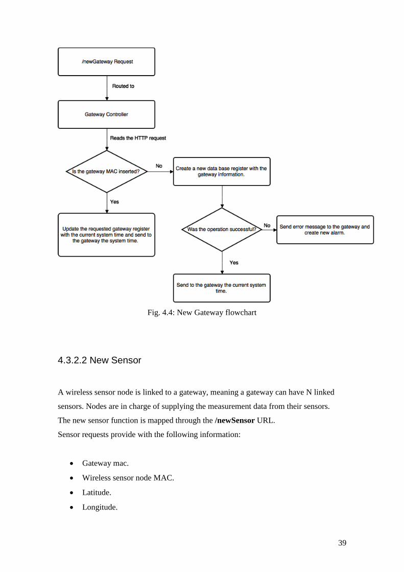
39
Fig. 4.4: New Gateway flowchart
4.3.2.2 New Sensor
A wireless sensor node is linked to a gateway, meaning a gateway can have N linked
sensors. Nodes are in charge of supplying the measurement data from their sensors.
The new sensor function is mapped through the /newSensor URL.
Sensor requests provide with the following information:
Gateway mac.
Wireless sensor node MAC.
Latitude.
Longitude.

40
When this URL is called, the following logic is performed:
A call to the newSensor function within the sensor controller is made.
The systems checks if the supplied gateway mac is inserted in the system.
If it is not found, an error message is sent.
If the gateway is found, a query is made for checking if there are any sensors
inserted with that mac.
If no sensor is found, a new sensor is inserted and a primary key ID is sent as a
response to the WSN (the WSN will communicate via this Id for to create new
measurements) as well as indicating the success of the operation.
If a sensor is found, it means that the sensor was switched off and now is on, and
the Id found is sent back.
Otherwise, if any error occurs, an error message is sent and an alarm is created.

41
Fig. 4.5: New Sensor flowchart
4.3.2.3 New Measurement
Once a gateway and a sensor are signed up in the system, the WSN is ready for sending
measurements data. The measurement_type table includes all the expected
measurements to be found in the URL encoded http request via the short_name field.
The new measurement request should provide the following information:
The Id associated with the measurements.
All the values for the measurements with URL key value being the same as the
short name.

42
The new measurement is inserted through the /newMeasurement URL. When a request
is received, the following logic is performed:
A call to the newMeasurement function within the measurement controller is
made.
System checks if the sensor is inserted in the DB.
If it is not found, an error message is sent.
If it is found, a query is made to the measurement_type for obtaining all the
measurement types in the system.
The URL values are looped checking for the short values found in the query of
the previous step.
If a value is found, then a register is created in the measurement table.
Finally, if everything ends successfully, an Ok response is sent.

43
Fig. 4.6: New measurement flowchart
44
4.3.2.4 New Alarm
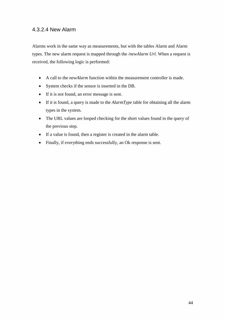
Alarms work in the same way as measurements, but with the tables Alarm and Alarm
types. The new alarm request is mapped through the /newAlarm Url. When a request is
received, the following logic is performed:
A call to the newAlarm function within the measurement controller is made.
System checks if the sensor is inserted in the DB.
If it is not found, an error message is sent.
If it is found, a query is made to the AlarmType table for obtaining all the alarm
types in the system.
The URL values are looped checking for the short values found in the query of
the previous step.
If a value is found, then a register is created in the alarm table.
Finally, if everything ends successfully, an Ok response is sent.

45
Fig. 4.7: New Alarm flowchart
46
4.3.3 Web app API
The web app API, or the URLs designed for the client side, are the ones used by the
angular frontend application. Although they have been designed for this application,
because of the decoupled nature of the system architecture, these could be used for
serving any other client side device like a smartphone. No extensive explanation will be
carried in this section as this will later discussed in the front end section.
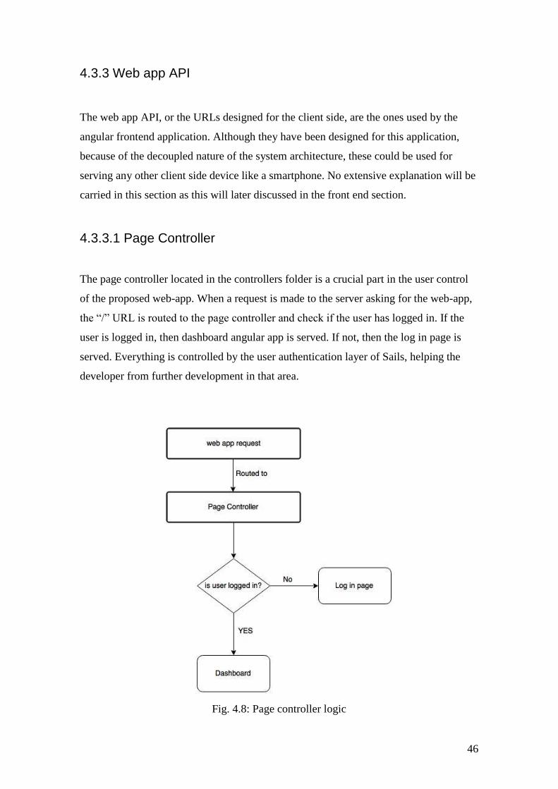
4.3.3.1 Page Controller
The page controller located in the controllers folder is a crucial part in the user control
of the proposed web-app. When a request is made to the server asking for the web-app,
the “/” URL is routed to the page controller and check if the user has logged in. If the
user is logged in, then dashboard angular app is served. If not, then the log in page is
served. Everything is controlled by the user authentication layer of Sails, helping the
developer from further development in that area.
Fig. 4.8: Page controller logic

47
The rendered views are located in the views folder under homepage.ejs for the login and
dashboard/index.ejs for the dashboard (rendered by Sails template engine)
4.4 Front End
The front end section will include all the logic for developing the web application. As
mentioned in previous chapter, the app will use as main components the Angular.js
framework and Twitter Bootstrap CSS style framework.
This section will provide information regarding the logical implementation with no
regards to the user interface design as this will be covered in the next chapter. A
detailed view of the application will be featured in the next chapter.
4.4.1 Angular.js app components
Angular.js is a single page style framework, which means that the browser does not
refresh or access new html files every time a link is clicked.Therefore all the logic relies
beneath the JavaScript layer. Any Angular application should contain the following
elements:
Directives: Directives are extended Html attributes with the prefix –ng. Any
Angular element defined in the webpage should contain this prefix to be
interpreted as an Angular element. Apart from the stock directives, custom ones
can be created for encapsulating new functionalities. This project will include
some 3rd
party open source directives for maps and statistics manipulation.
Angular Module: An angular module is a directive that defines an Angular app.
So every single page application should be defined as angular module. This
component is defined in a JavaScript file and imported into the html. The
Entomatic web app will feature two modules (as described in page controller
section):
o Login Module
o Dashboard Module
Controller: A controller is the a directive that creates a communication layer
between the HTML and the JavaScript for DOM manipulation. At least one

48
Controller is needed for each module. As a way of providing with good
practices, the app will have a controller for each screen.
Other no essential components but that will be used in the implementation:
Services: So as to group all the HTTP requests to the API, the framework
provides a service characteristic for encapsulating and avoiding repetition of
common used server requests. The proposed platform will feature a service file
for grouping all HTTP requests. The different controllers will implement the
HTTP server request via the service injection (dependency injection).
Router: Organizing the different screens (user interface elements) into router
logic helps application maintenance and the development of new features.
Angular features a stock router but with limited features. The ui-router
directive[19] that will be used in this project, is the de-facto interface routing
used in Angular apps, and provide with extra functionalities.
All the necessary JavaScript files are located in the Sails.js assets folder.
4.4.2 Login module
The login module, linked to the view homepage.ejs, is in charge of providing the user a
way to access to the web app. User authentication includes a username and a password
as way to authenticate. Once the user has been authenticated, the page controller
redirects the user to the dashboard view.
4.4.2.1 User authentication
User authentication data is stored in the users table. The user information includes user
name and a bCrypt [20] hashed password.
The system enables to create, log in, and log out users. The angular controller,
loginController, is responsible of obtaining the data of the form and sending it to Sails.
Authentication in done in the following way:
The loginController obtains the data and is sent to Sails via the PUT method
/login.

49
The user controller function of the server encrypts the password and checks if
the user is in data base and if the supplied password matches with the one stored.
If user authentication is succesful, the user associated with the client is stored in
the Sails session manager and the pageController redirects the user to the
dashboard.
Otherwise, a bad request is sent to the front end meaning something has failed
and an error message is shown.
4.4.3 Dashboard module (main module)
The Dashboard module includes the main app for managing the data from the WSN and
is the core part of the web application. The angular module is defined in the
mainModule.js file. All the application uses Bootstrap components for representing the
different contents of the screen.
4.4.3.1 CSS components
All the application uses the CSS components from the bootstrap framework. Some of
items that will be used are the following:
Buttons.
Panels.
Navigation Bar.
Dropdown menus.
Tables.
Pagination components.
4.4.3.2 UI routing
Following the initial specifications regarding the basic requirements to be implemented,
and using the UI-Router directive for interface routing, fig 4.5 shows the logic interface
diagram of the application.

50
Fig. 4.9: Interface Structure dependecy
The routing file is located under assets\js\private\dashboard\Router and defines the
routes of the diagram:
angular.module('MainModule').config(function($stateProvider, $urlRouterProvider){
// For any unmatched url, send to /route1
$urlRouterProvider.otherwise("/main/home");
$stateProvider
.state('main', {
url: "/main",
templateUrl: '/views/main.html',
controller: 'MainController'
})
.state('main.home', {
url: "/home",
templateUrl: '/views/home.html',
controller: 'HomeController'
})
.state('main.sensorLocation', {
url: "/sensorLocation",
params: {
param: 'noSensor'
},
templateUrl: '/views/sensorLocation.html',
controller: 'SensorLocationController'
})
.state('main.statistics', {
url: '/statistics',
params: {

51
param: 'noSensor'
},
templateUrl: '/views/statistics.html',
controller:'StatisticsController'
})
.state('main.alarms', {
url: '/alarms',
params: {
param: 'noSensor'
},
templateUrl: '/views/alarms.html',
controller:'AlarmController'
})
.state('main.config', {
url: '/config',
templateUrl: '/views/config.html',
controller:'ConfigController'
})
});
Each different screen is a state, meaning the app knows where the user is located and
making it possible to easily move from one screen to another. Each different view
depends of the main screen and is defined in a separate HTML file as shown in the code
extract.
For a view, the following html tag is inserted in the main document:
<div ui-view></div>
All html files can be located under /assets/views.

52
Fig. 4.10: The dashboard screen distribution
4.4.3.4 Main
The main screen, defined in the main.html and using the mainController.js, is the
template screen for containing the nested views.
The included elements are the following:
Top Navigation Bar:
o User name information
o Log Out button
Lateral navigation bar for accessing the different screens.
This screen uses the following backend API methods via AJAX calls for obtaining the
user information and for logging out.
'GET /logout': 'UserController.logout'
'GET /getInitValues': 'UserController.getInitValues'

53
4.4.3.5 Home
The home screen is the default view that is rendered when accessing the application.
The screen is defined in the home.html file and uses the homeController.js controller.
This view provides this information:
Lists all the active nodes and gateways
Gets the last 24h node/sensor measurement
This is done via the following AJAX call:
'GET /getDailyReport': 'GatewayController.getDailyReport'
4.4.3.6 Sensor Location
The sensor location screen is defined in the sensorLocation.html file and uses the
sensorLocationController.js.
In the sensor location screen the user is able to view in a map the active gateways and
their sensors. The map service is provided by Google Maps using the Angular Google
Maps directive. The information for showing this data is done thought the following
API methods:
'GET /getGateways': 'GatewayController.getGateways',
'GET /getSensors': 'SensorController.getSensors'
WebSockets technology (offered as a stock option from Sails.js) is used for offering
real-time gateway and sensor synchronization information.
This is done by using the publish-subscribe pattern in which the application is
subscribed to the event of new gateway or new sensor synchronization. When the event

54
is triggered, the Angular application refreshes the screen with the new inserted
information.
4.4.3.7 Statistics
The sensor location screen is defined in the statistics.html file and uses the
statisticsController.js.
This screen is meant for visualizing the sensor‟s measurement data filtered by the
measurement type, the sensor and a time period. The data is visualized through a chart,
provided by Google Chart API and packaged through a custom directive, and a table for
raw data visualization. An export to CSV option is also available.
The following API methods are used for retrieving the data:
'GET /getSensors': 'SensorController.getSensors'
'GET /getMeasurementTypes': 'MeasurementTypeController.getMeasurementTypes',
'GET /getSelectedMeasurement': MeasurementController.getSelectedMeasurement',
WebSockets technology is also used in a similar way as the sensors location for real
time measurement updates.
4.4.3.8 Alarms
The sensor location screen is defined in the alarms.html file and uses the
alarmsController.js.
The alarms screen is composed by two main features: One collapsable panel enables the
user to view the new alarms and mark them as viewed, and another one that should be
used for searching the historic alarms.
A new alarm is no longer a new alarm when the Boolean value viewed from database
has been set on true.
The following API methods are used for this purpose:

55
'GET /getSelectedAlarms': 'AlarmController.getSelectedAlarms',
'GET /getUnviewedAlarms': 'AlarmController.getUnviewedAlarms',
'PUT /setViewedAlarm': 'AlarmController.setViewedAlarm',
'GET /getSensors': 'SensorController.getSensors',
'GET /getAlarmTypes': 'AlarmTypeController.getAlarmTypes'
4.4.3.9 Configurations
The sensor location screen is defined in the config.html file and uses the
configController.js.
This screen is used for adding new types of measurement, new types of alarm, and to
create new users.
The following API methods are used:
'POST /newMeasurementType': 'MeasurementTypeController.newMeasurementType',
'POST /newAlarmType': 'AlarmTypeController.newAlarmType',
'POST /signup': 'UserController.signup',
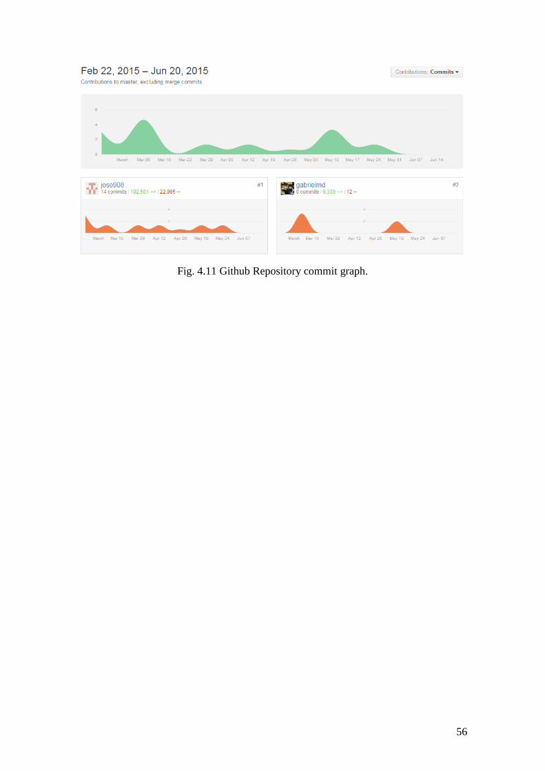
4.5 Version control
Although no special focus was made into version control, several commits where done
during the development of the system. The main use of the repository was a way to
store all the source code so then it could be easy to be deployed in the server using the
clone command.
Also, using the provided issue tool from GitHub, supervisors were able to report all the
problems related with the application in a proper way.
56
Fig. 4.11 Github Repository commit graph.

57
Chapter 5: Web Application walkthrough
This chapter contains information regarding the user interface and usage of the
developed web application.
5.1 Login
When the user accesses the “/” default URL through a web browser, the login
application is served. The user is then asked for its credentials (fig X)
Fig. 5.1: Login screen
If the authentication fails, either because the user doesn‟t exist or the password is
wrong, an error message is shown. If authentication is successful, then browser redirects
to the dashboard page.

58
Fig. 5.2 Login authentication has failed.
5.2. Dashboard
The Dashboard page is where the WSN management is done. The dashboard is capable
of locating in a map the gateways and the nodes/sensors attached to the system,
visualizing through a chart the desired measurements, and manage the alarms generated
by the system.
Fig 5.3 shows the home page of the dashboard.

59
Fig. 5.3: General view of the dashboard
5.2.1 Top Navigation bar
The top navigation bar is used for user information and for logging the user out.
Fig: 5.4 top navigation bar detail
5.2.2 Lateral navigation bar
The lateral bar is meant for accessing the different screens that the dashboard is
composed of. The Alarm icon provides a number for showing the current unviewed
alarms.

60
Fig. 5.5: Lateral navigation bar detail
5.2.3 Home
The home screen is the start point of the dashboard where the user is informed with
relevant data such as the number of active gateways and nodes, as well as showing the
last 24h measurements. Also, a quick link access to different screens is found.

61
Fig. 5.6: Home page detail
5.2.4 Sensor location
In the sensor location screen the user can locate through a map the sensors and
gateways attached to the system. Gateways are marked in blue while sensors in red.
When a sensor or gateway is clicked, a window appears. This window shows
information about the coordinates, the id, and the mac. Also, if a sensor is selected, the
user can access its measurements and alarms.

62
Fig 5.7: Map detail from the sensor location screen
Apart from the map view, there are two collapsable lists:
Gateway: Shows all the gateways attached to the system. If one item is clicked,
then map will navigate to the gateway point and open the gateway window.
Sensor: If a sensor is clicked, then the map will show the selected item. Also,
obtaining information regarding the gateway, the measurements and alarms can
be done via click to the icons.

63
Fig. 5.8: Gateway and Sensor detail list
One interesting feature is the capability that share the sensor location, the statistics and
alarms screen of switching between different screens for a selected node.

64
Fig. 5.9. Graph showing the relations between the different screens
5.2.5 Statistics
From the statistics screen, the user can visualize the measurements in a chart for a
selected sensor.
Fig. 5.10: Statistics screen overview

65
The screen has a node selector and a measurement type selector, from which the user
can obtain a chart representation in desired time period.
Fig. 5.11: Statistics filter
Also, access to the selected node map location and alarms can also be found.
If the multiple check is selected, then multiple nodes can be visualized for a selected
measurement type and period type.
Fig. 5.12: More than one node per graph

66
5.2.6 Alarms
The Alarms screen has two main collapsable panels: One enables the user to view the
new alarms and mark them as viewed, and the other is used for searching the historic
alarms.
Fig. 5.13: Alarm screen
Also, access to the selected node map location and measurements can be found.
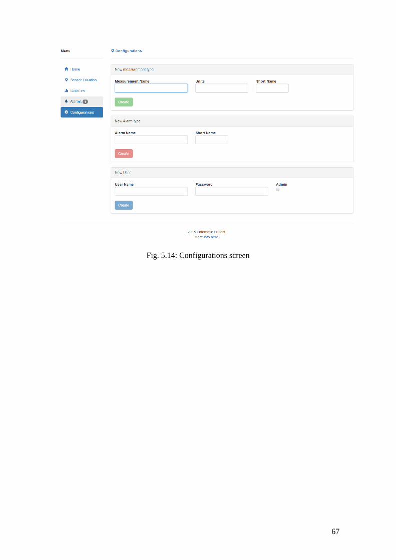
5.2.7 Configurations
Configuration screen is designed to add new users, new measurement types, and new
alarm types.
67
Fig. 5.14: Configurations screen

68

69
6. Deployment and Testing
Once the platform has been developed and tested in a local environment, integrated tests
in a simulated real environment should be done for verifying the correct operation of the
system.
6.1 Deployment
The Sails.js server and the PostgreSQL database server have been deployed in a testing
environment supplied by the university. This server is located at the UPF facilities and
can only be accessed within the network or through the VPN, using the following URL:
http://em-test.s.upf.edu/ (port 80)
6.2 Testing scenario
As a way to test the platform in a real scenario, a WSN was simulated in the laboratory
using a gateway and a node. The features tested by the WSN where gateway
synchronization, sensor/node synchronization and sensor measurements. The testing
scenario was composed of two nodes linked to a gateway which sent through the
university network the data gathered by the WSN to the platform server.
Fig. 6.1: Testing scenario

70
6.2.1 Measurement types
The measurements expected by the system were (where physical sensor was not
available, simulated data was used):
Temperature: Provided by a temperature sensor.
Voltage: The current voltage value supplied by the battery.
Relative humidity: Provided by a relative humidity sensor.
Light: Fixed value set to 50%.
Olive fruit fly counter: Using a random number generator.
These types of measurements were inserted in the system via the MeasurementType
table for proper recognition by the system.
6.2.2 WSN Hardware
The hardware used for the simulation were two Waspmote nodes, one acting as a node,
and the other one acting as a gateway.
The information relating to the coordinates was also simulated.

71
Fig. 6.2: Waspmote Gateway
Fig: 6.3 Waspmote Gateway with a case.

72
Fig: 6.4 Waspmote Node with temperature sensor.
Fig. 6.5: Waspmote Node
73
6.2.3 WSN simulation results
Two major results were crucial in order to validate the correct operation of the system,
the WSN synchronization with the platform server, and the validation of the sent
measurements.
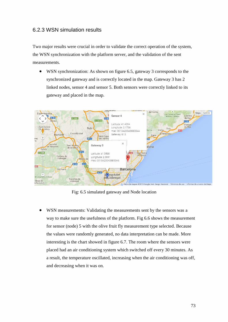
WSN synchronization: As shown on figure 6.5, gateway 3 corresponds to the
synchronized gateway and is correctly located in the map. Gateway 3 has 2
linked nodes, sensor 4 and sensor 5. Both sensors were correctly linked to its
gateway and placed in the map.
Fig: 6.5 simulated gateway and Node location
WSN measurements: Validating the measurements sent by the sensors was a
way to make sure the usefulness of the platform. Fig 6.6 shows the measurement
for sensor (node) 5 with the olive fruit fly measurement type selected. Because
the values were randomly generated, no data interpretation can be made. More
interesting is the chart showed in figure 6.7. The room where the sensors were
placed had an air conditioning system which switched off every 30 minutes. As
a result, the temperature oscillated, increasing when the air conditioning was off,
and decreasing when it was on.

74
Fig: 6.6 Olive fruit fly measurements

75
Fig: 6.7 temperature measurements

76

77
Chapter 7: Conclusions
A web platform for managing WSNs has been presented. The first chapters included an
introduction to the concept of WSN to later introduce the reader into the available
technologies for developing the platform. Although the selected tools were the ones
suggested by the specification of the Entomatic project, their use provided an easy
development with a moderate learning curve.
The development was carried taking into account maintainability and scalability
constraints, thus providing a viable model for the early development of the Entomatic
project. The platform testing was the crucial part for ensuring the correct functioning of
system, although close communication was established with the supervisors for
ensuring that everything was going in the right direction.
In spite of being a simple prototype, the results have provided to fulfill with the original
set project scope and being completely functional in development environments.
It has been a wonderful opportunity to develop from scratch a system for managing
WSNs and being able to solve complex problem using the available resources. Learning
new technologies has also provided me with a new perspective of modern web
development, helping me in developing my professional career.
7.1 Future work
The implemented platform could be improved in several ways:
Security: The testing environment was set within a private network, meaning
undesired access was not going to be found. If the platform had to be set in a
production environment, the following points should be taken into account:
o API private keys: The way the restful API is designed, it is not guaranteed that
any unwanted user can perform undesired actions. Using a private key for API
clients ensures that only users with this key can use it.
o Client password encryption: Although password user‟s passwords are stored
encrypted in the data base, client sends the HTTP authentication request with no
encryption, which means that any network sniffer could trace and obtain the user

78
credentials. Using the HTTPS protocol could be an easy solution for solving this
problem.
User permissions: The current implementation has no support for user permissions.
Final product should have user filtering depending on the user that wishes to access
the platform.
Custom UI: Instead of using the Bootstrap framework, which is ideal for this sort
of prototype development, final product could use a custom framework for more
specific and accurate design.
Bidirectional WSN communication: Current WSN communication with the
system is only done in one direction. In other words, only data coming from it can
be received. Bidirectional communication would increase system reliability as more
WSN information can be obtained (check if sensors are switched off, battery status
etc.).

79
Bibliography
[1] Ashtom, K. That „Internet of Things‟ Thing. In the real world, things matter more
than ideas. RFID Journal, 22 June 2009. Available from: http://www.rfi
djournal.com/articles/view?4986
[2] Bröring, A. et al. New generation sensor web enablement. Sensors, 11, 2011, pp.
26522699. ISSN 1424-8220. Available from: doi:10.3390/s110302652
[3] Entomatic project UPF (2015) Retrieved 10 June 2015
http://entomatic.upf.edu/concept-objectives
[4] Zhang, Q., Cheng, L., & Boutaba, R. (2010). Cloud computing: state-of-the-art and
research challenges. Journal of internet services and applications, 1(1), 7-18.
[5] Zhang, H. (2013). Architecture of Network and Client-Server model. arXiv preprint
arXiv:1307.6665
[6] Berners-Lee, T.; Fielding, R. (January 2005). "Uniform Resource Identifier (URI):
Generic Syntax". www.ietf.org. Network Working Group. Retrieved 2014-09-05.
[7] Fielding, Roy T.; Gettys, James; Mogul, Jeffrey C.; Nielsen, Henrik Frystyk;
Masinter, Larry; Leach, Paul J.; Berners-Lee, Tim (June 1999). Hypertext Transfer
Protocol -- HTTP/1.1. IETF. RFC 2616.
[8] Fielding, R. T.; Taylor, R. N. (2000). "Principled design of the modern Web
architecture". pp. 407–416. doi:10.1145/337180.337228
[9] "More deeply, the framework exists to separate the representation of information
from user interaction." The DCI Architecture: A New Vision of Object-Oriented
Programming - Trygve Reenskaug and James Coplien - March 20, 2009.
[10] "What is Object/Relational Mapping?". Hibernate Overview. JBOSS Hibernate.
Retrieved 02 June 2015. http://hibernate.org/orm/what-is-an-orm/

80
[11] Ka-Ping, Yee. "Definition of a Mediator". Ka-Ping. In the context of WWW
applications, a mediator is a service that functions simultaneously as a server on its
front end and as a client on its back end.
[12] "ASP.NET MVC, Web API,Web Forms, Razor and Open Source - ScottGu's
Blog". Weblogs.asp.net. Retrieved 02 June 2015.
[13] "Inner-Browsing: Extending Web Browsing the Navigation Paradigm". Retrieved
04 June 2015. https://developer.mozilla.org/en-US/docs/Inner-
browsing_extending_the_browser_navigation_paradigm
[14] Jesse James Garrett (18 February 2005). "Ajax: A New Approach to Web
Applications". AdaptivePath.com. Archived from the original on 2 July 2008. Retrieved
19 June 2008
15] "The application/sql Media Type, RFC 6922". Internet Engineering Task Force.
April 2013. p. 3. Retrieved 10 April2013.
[16] "Rapid Subversion Adoption Validates Enterprise Readiness and Challenges
Traditional Software Configuration Management Leaders". Collabnet. May 15, 2007.
Retrieved October 27, 2010. Version management is essential to software development
and is considered the most critical component of any development environment.
[17] F. Beck, S. Diehl. On the Congruence of Modularity and Code Coupling. In
Proceedings of the 19th ACM SIGSOFT Symposium and the 13th European
Conference on Foundations of Software Engineering (SIGSOFT/FSE '11), Szeged,
Hungary, September 2011. doi:10.1145/2025113.2025162
[18]Tobi Borlinghaus Daniel Clasen (2015) Comparison of 4 popular JavaScript MV*
frameworks retrieved 06 June 2015 http://www.developereconomics.com/comparison-
4-popular-javascript-mv-frameworks-part-2/
[19] AngularUI Router retrieved 05 June 2015 https://github.com/angular-ui/ui-router
[20] Provos, Niels; Talan Jason Sutton 2012 (1999). "A Future-Adaptable Password
Scheme". Proceedings of 1999 USENIX Annual Technical Conference: 81–92.