web configuration 2008 mrd-310 - beijer...
TRANSCRIPT

3G Cellular Modem / Router
Web configuration reference guide
www.westermo.com
RE
V.b
662
3-32
01 2008-10 M
älartryck AB, Eskilstuna, Sweden
©Westermo Teleindustri AB • 2008Web configuration
reference guide6623-3201 MRD-310
MRD-330

2 6623-3201
1 Basic Configuration ...................... 4
1.1 Configure the 3G Wireless interface .. 4
1.1.1 Network Configuration .......................... 5
1.1.2 Setting the SIM card PIN ........................ 5
1.1.3 Adding a Network
Connection Profile ................................... 6
1.1.4 Enable the Wireless Connection .......... 9
1.1.5 Checking the Status of the
Connection ..............................................10
1.2 Configure the LAN interface and
DHCP Server ..........................................12
1.2.1 Setting the IP Address ...........................12
1.2.2 Enabling DHCP .......................................12
1.3 Configure clients to use the
MRD-3xx ..................................................14
2 System Administration .............. 15
2.1 Administration ........................................15
2.2 System Information ................................17
2.3 Configuration Backup & Restore .......18
2.4 Firmware Upgrade .................................20
2.5 SNMP ........................................................22
2.6 GPIO .........................................................23
3 Wireless Interface Configuration 24
3.1 Network Configuration ........................25
3.1.1 Wireless Operating Mode ...................26
3.1.2 Operating Frequency Band ..................27
3.1.3 Setting the SIM card PIN ......................27
3.2 Packet Mode Configuration .................29
3.2.1 Adding a Network Connection
Profile ........................................................29
3.2.2 Deleting a Profile....................................32
3.2.3 Editing a Profile .......................................33
3.2.4 Enable the Wireless Connection ........34
3.2.5 Checking the Status of the
Connection ..............................................35
3.3 Connection Management .....................39
3.3.1 Connection Establishment ...................40
3.3.2 Connection Maintenance .....................42
3.3.3 Remote Poll Setup .................................43
3.3.4 Miscellaneous Options ..........................44
3.3.5 Connect on Demand ............................45
3.4 Circuit Switched Data (CSD) Mode..45
3.4.1 CSD Single Port......................................46
3.4.2 CSD Multiplexed ....................................47
3.5 SMS Triggers ............................................50
3.5.1 Trigger configuration .............................50
3.5.2 Access Control .......................................52
3.5.2.1 Example: Default policy accept.........53
3.5.2.2 Example: Default policy to Drop .....54
4 Network ...................................... 56
4.1 LAN Interface .........................................56
4.1.1 Changing the IP Settings of the
LAN Interface .........................................56
4.1.2 Disabling the LAN Interface ................58
4.2 DHCP Server Configuration ...............59
4.3 Configuring clients to use the
MRD-3xx ..................................................60
4.4 Domain Name System (DNS) ............61
4.4.1 DNS Proxy ..............................................61
4.4.2 Manual DNS Configuration .................62
4.4.3 Dynamic DNS Client Configuration..62
5 Firewall ........................................ 64
5.1 Firewall Setup ..........................................64
5.1.1 Network Address and
Port Translation (NAPT) ......................65
5.1.2 Stateful Packet Inspection (SPI) .........65
5.1.3 Connection tracking options...............66
5.2 Access Control .......................................67
5.2.1 Accessing unit services from the
wireless port or VPN tunnels .............68
5.3 DoS Filters ...............................................69
5.3.1 Enabling the Denial of Service filters 70
5.4 Custom Filters ........................................71
5.4.1 Description ..............................................71
5.4.2 New Custom Filter Options ...............72
5.4.3 Adding a new custom filter .................75
Table of Contents

36623-3201
5.4.4 Editing a Custom Filter .........................79
5.4.5 Deleting a Custom Filter......................81
5.5 Port Forwarding .....................................83
5.5.1 Port Forward Options ..........................84
5.5.2 Adding a new port forward .................86
5.5.3 Editing a port forward ..........................89
5.5.4 Deleting a port forward .......................91
5.6 Custom NAT ...........................................93
5.6.1 Description ..............................................93
5.6.2 Custom NAT Options ..........................94
5.6.3 Adding a new custom NAT .................97
5.6.4 Editing a Custom NAT .......................100
5.6.5 Deleting a Custom NAT ....................102
6 Virtual Private Network (VPN) 104
6.1 Secure Sockets Layer (SSL) VPN. ......105
6.1.1 SSL VPN Configuration .......................106
6.1.2 Connecting to a VPN Server .............110
6.2 Internet Protocol Security
(IPsec) VPN ............................................115
6.2.1 General IPsec Configuration .............115
6.2.2 Adding an IPsec Tunnel .......................118
6.2.3 IPsec Configuration Example.............130
6.3 PPTP and L2TP .....................................138
6.3.1 Point-to-Point-Tunneling-Protocol ...138
6.3.2 Layer 2 Tunnel Protocol ......................139
6.3.3 PPTP and L2TP Configuration ..........140
6.3.4 Add a PPTP or L2TP Tunnel ..............141
6.3.5 PPTP Configuration Example ............143
6.4 Multiple VPN Tunnels ...........................147
6.5 Certificate Management .....................148
6.5.1 Add a Certificate ..................................149
6.5.2 Checking the Certificate Details ......151
6.5.3 Adding Further Certificates...............152
6.5.4 Deleting a Certificate ..........................154
7 Serial Server ............................. 156
7.1 Selecting a port function ....................156
7.2 Common configuration options .......158
7.2.1 Serial port settings ...............................158
7.2.2 Packet framer settings ........................160
7.3 Raw TCP Client/Server .......................162
7.3.1 Description ............................................162
7.3.2 Selecting the port function ................162
7.3.3 Configuring the port function ...........163
7.4 Raw UDP ...............................................166
7.4.1 Description ............................................166
7.4.2 Selecting the port function ................166
7.4.3 Configuring the port function ...........167
7.5 Unit Emulator .......................................169
7.5.1 Description ............................................169
7.5.2 Selecting the port function ................169
7.5.3 Configuring the port function ...........170
7.6 DNP3 IP-Serial Gateway ....................174
7.6.1 Description ............................................174
7.6.2 Selecting the port function ................175
7.6.3 Configuring the port function ...........176
7.7 Modbus IP-Serial Gateway .................180
7.7.1 Description ............................................180
7.7.2 Selecting the port function ................180
7.7.3 Configuring the port function ...........181
7.8 Telnet (RFC 2217) Server ..................183
7.8.1 Description ............................................183
7.8.2 Selecting the port function ................184
7.8.3 Configuring the port function ...........185
7.9 Phone Book ...........................................187
7.9.1 Description ............................................187
7.9.2 Phone Book Options ..........................188
7.9.3 Adding a new phone book entry .....189
7.9.4 Editing a phone book entry ...............192
7.9.5 Deleting a phone book entry ............193
8 AT Command set ..................... 195

4 6623-3201
1 Basic Configuration
The three sections below detail the steps needed to config-ure the MRD-3xx for basic packet mode functionality. For details on configuring the unit for Circuit Switched mode and for more advanced configuration refer to the Advanced Configuration section.
1.1 Configure the 3G Wireless interface
To access the configuration page for the 3G Wireless inter-face, click on Wireless. The Basic Wireless configuration page will be displayed as shown in Figure 1.
Figure 1: Wireless Interface Basic configuration.
56623-3201
1.1.1 Network Configuration
The Network Configuration section contains the settings for the operational mode and the frequency band of the unit, the default settings will usually be adequate to connect the unit to a packet based network.
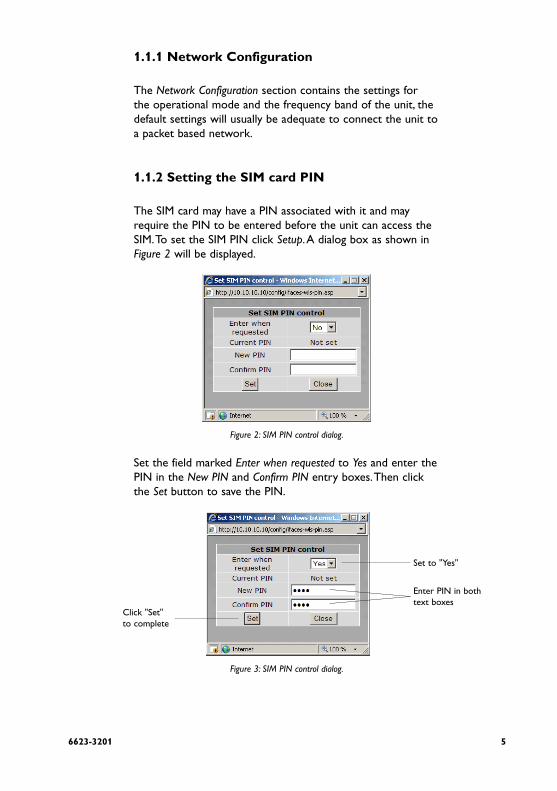
1.1.2 Setting the SIM card PIN
The SIM card may have a PIN associated with it and may require the PIN to be entered before the unit can access the SIM. To set the SIM PIN click Setup. A dialog box as shown in Figure 2 will be displayed.
Figure 2: SIM PIN control dialog.
Set the field marked Enter when requested to Yes and enter the PIN in the New PIN and Confirm PIN entry boxes. Then click the Set button to save the PIN.
Figure 3: SIM PIN control dialog.
Set to "Yes"
Enter PIN in bothtext boxes
Click "Set"to complete

6 6623-3201
1.1.3 Adding a Network Connection Profile
To access the wireless packet mode settings click on the Packet mode tab. The screen shown in Figure 4 will be displayed. The page shows the connection configuration details and is divided into two sections. The first section shows the current connection state and the selected profile and the second sec-tion lists the available profiles. A connection profile groups together the settings required to connect to a provider's network. The unit allows multiple profiles to be configured to allow quick changes to the network connection settings. For most applications only one profile is required.
Figure 4: Wireless Interface Packet mode settings
76623-3201
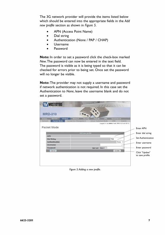
The 3G network provider will provide the items listed below which should be entered into the appropriate fields in the Add new profile section as shown in Figure 5.
APN (Access Point Name)•Dial string•Authentication (None / PAP / CHAP)•Username•Password•
Note: In order to set a password click the check-box marked New. The password can now be entered in the text field. The password is visible as it is being typed so that it can be checked for errors prior to being set. Once set the password will no longer be visible.
Note: The provider may not supply a username and password if network authentication is not required. In this case set the Authentication to None, leave the username blank and do not set a password.
Figure 5: Adding a new profile.
Enter APN
Enter dial string
Set Authentication
Enter username
Enter password
Click "Update" to save profile

8 6623-3201
Once the data has been entered click the Update button to add the profile. The screen will now change to show the added profile as shown in Figure 6. As this is the only profile entered it will be automatically selected as the current profile and the profile entry will be shaded green to indicate that it is the selected profile.
Figure 6: Profile added and selected.

96623-3201
1.1.4 Enable the Wireless Connection
To complete the configuration of the wireless connection, set the Connection state to Always connect and click the Update button to save the changes. Once the changes have been set, the MRD-3xx will initiate a 3G connection. Connection will normally take up to 30 seconds. Figure 7 shows the completed wireless configuration.
Figure 7: Completed wireless configuration.

10 6623-3201
1.1.5 Checking the Status of the Connection
To check the status of the connection select Status from the top level menu and then select Wireless from the second level menu. The Wireless status page will be displayed which will look similar to that shown in Figure 8. The status of the con-nection will change as the unit connects to the network, first it will report Checking then Connecting and finally Connected. To see the value changing the page will need to reload.
Figure 8: Wireless Status page.
Note: If the status is reported as Error then check that the profile settings have been entered correctly as shown in Section 3.2.1Once connected the Status Alarms page should have no faults listed as shown in Figure 9

116623-3201
Figure 9: Status alarm page.
12 6623-3201
1.2 Configure the LAN interface and DHCP Server
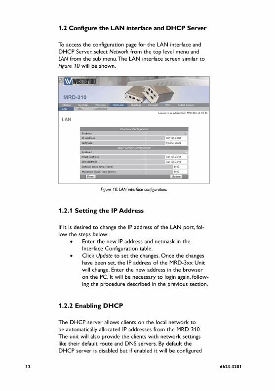
To access the configuration page for the LAN interface and DHCP Server, select Network from the top level menu and LAN from the sub menu. The LAN interface screen similar to Figure 10 will be shown.
Figure 10: LAN interface configuration.
1.2.1 Setting the IP Address
If it is desired to change the IP address of the LAN port, fol-low the steps below:
Enter the new IP address and netmask in the •Interface Configuration table.Click • Update to set the changes. Once the changes have been set, the IP address of the MRD-3xx Unit will change. Enter the new address in the browser on the PC. It will be necessary to login again, follow-ing the procedure described in the previous section.
1.2.2 Enabling DHCP
The DHCP server allows clients on the local network to be automatically allocated IP addresses from the MRD-310. The unit will also provide the clients with network settings like their default route and DNS servers. By default the DHCP server is disabled but if enabled it will be configured

136623-3201
to serve IP addresses in the range 192.168.2.210 through 192.168.2.240, and the Default and Maximum lease times have been set to 1440 minutes. So if these values are consistent with the network that the MRD-310 is connected to, then the DHCP can be enabled by setting the Enabled field to Yes and clicking the Update button. If the standard settings are not applicable for the connected network, then refer to Figure 11 and follow the steps below, to configure the DHCP server:
Figure 11: DHCP configuration.
Choose a group of available IP addresses on the •local network. For example, if the IP address of the MRD-3xx is 192.168.2.200 with a net-mask of 255.255.255.0, a group chosen could be 192.168.2.210 to 192.168.2.240. This will provide 31 addresses for clients.Under the DHCP Server Configuration table, •
Set the o Enabled option to Yes.Enter the first address of the group in the o Start Address box.Enter the last address of the group in the o End Address box.Enter a lease time for the o Default Lease time.Enter a lease time for the o Maximum Lease time.
Click • Update to set the changes.
Set to "Yes" to enable DHCP server
Set the DHCP IP address range
Set the DHCP lease times
Click "Update" to save changes

14 6623-3201
1.3 Configure clients to use the MRD-3xx
The MRD-3xx will act as a gateway for connections destined over the wireless interface. The default configuration will pro-vide Network Address Translation and firewalling to protect clients on the local network.
To configure clients to use the MRD-3xx as their gateway:If the clients have a DHCP address allocated by the •MRD-3xx, they will have learned the necessary set-tings. No further configuration is needed.If clients have static IP addresses, set their default •route and DNS server to the IP address of the MRD-3xx.

156623-3201
2 System Administration
The System Administration functions are accessed by selecting the System tab of the main menu.
2.1 Administration
To access the Administration features, select •Administration from the System sub-menu, a page similar to that shown in Figure 12 will be displayed.
Figure 12: System Administration page.

16 6623-3201
The options available are:
Hostname • Set the required hostname for the MRD-3xx.•
Check time with NTP Server • Set to Yes to synchronise the internal clock with a NTP server.
Timezone • Specify the timezone for location of the MRD-3xx.
Manually set time • Click button to set time manually.
Edit users and passwords • Click button to edit users and passwords.
Timed reboot • Specify a time in hours after which the MRD-3xx will automatically reboot. Set to 0 to disable automatic re-boot.
Reboot unit • Click the Reboot button to immediately reboot the MRD-3xx.

176623-3201
2.2 System Information
The MRD-3xx System Information is accessed by selecting the System Information tab from the System sub-menu. An example of the System Information page is shown in Figure 13. The first section of the page lists the Model and serial number of the unit, plus the firmware and boot-loader version. The seconds part of the page lists the LAN MAC address the IMEI of the wireless module, wireless IMSI ant the wireless software ver-sion.
Figure 13: System Information page.

18 6623-3201
2.3 Configuration Backup & Restore
The configuration of the MRD-3xx can be saved as a file to a PC. This file can then be used to restore the configuration of the unit at some later time or used to configure multiple units with the same configuration. To access the configuration back-up restore options select Backup & Upgrade from the System sub-menu. The Backup & Upgrade page will be displayed as shown in Figure 14.
Figure 14: Backup and Upgrade page.
To save the current configuration click on the link in the sec-tion titled Backup current configuration. A pop-up box similar to that shown in Figure 15 will be displayed, select Save to Disk and click OK and select a suitable location to save the file.
Figure 15: Save configuration.

196623-3201
To restore a configuration, click the Browse button in the sec-tion titled Restore a saved configuration select the configuration file, which should then be shown in the text box, as shown in Figure 16, click the Upload button to transfer the file to the MRD-3xx. Once the upload is complete, the MRD-3xx will need to be rebooted so the restored configuration can take affect. The details for performing a reboot can be found in the Administration section.
Figure 16: Restore configuration.

20 6623-3201
2.4 Firmware Upgrade
The MRD-3xx firmware can be upgraded via the web inter-face. To access the firmware upgrade page select Backup & Upgrade from the System sub-menu, the Backup & Upgrade page will be displayed as shown in Figure 17.
Figure 17: Backup and Upgrade page.
To upgrade the MRD-3xx firmware click the Browse button in the section titled Upgrade MRD-3xx firmware then select the navigate to and select the upgrade file.
Figure 18: Select firmware upgrade file.

216623-3201
To upload the file to the MRD-3xx click the Upload button. The file will now be uploaded to the MRD-3xx and, when it is complete, information on the upgrade file will be displayed, as shown in Figure 19. At this point the you can chose to can-cel the upgrade by clicking the Cancel Upgrade button.
Figure 19: Upload the upgrade file.
To proceed with the upgrade click the Upgrade button, the page will change to that shown in Figure 20. The firmware upgrade will now proceed.
Figure 20: Upload the upgrade file.
Note: The upgrade will take several minutes to complete after which the MRD-3xx will reboot, during this time the power to the MRD-3xx must not be removed.

22 6623-3201
2.5 SNMP
The MRD-3xx supports SNMP for network management of the unit. The SNMP configuration page can be accessed by selecting the SNMP tab of the System sub-menu.
Figure 21: The SNMP configuration page.

236623-3201
2.6 GPIO (MRD-330 only)
The MRD-330 has two general purpose digital inputs and two general purpose digital outputs, the options for these can be found by selecting GPIO on the System sub-menu.
Figure 22: The General Prupose I/O configutration page.

24 6623-3201
3 Wireless Interface Configuration
This section describes the 3G Wireless interface options of the MRD-3xx. The MRD-3xx supports two modes of opera-tion: packet mode and Circuit Switched Data (CSD) mode.
The Wireless menu contains the settings for the Wireless Interface. To display the settings, click on the Wireless tab on the top menu bar.
The subsections of the configuration are:
NetworkConfigure the operation mode, select the frequency band of operation and set the SIM PIN.
Packet modeConfigure the packet mode.
Connection ManagementAdvanced configuration of the network connection.
Circuit switched modeConfigure the circuit switched data mode.
SMSConfigure the Short Message Service (SMS) functionality of the unit.
EventsConfigure the event reporting of the unit.

256623-3201
3.1 Network Configuration
The Wireless Network options are used to set the operat-ing mode, select the frequency band of operation and set the SIM PIN. To display the Network page select Wireless from the main menu, the Network page is the default page displayed, it should appear similar to that of Figure 23.
Figure 23: Wireless Network configuration.

26 6623-3201
3.1.1 Wireless Operating Mode
The MRD-3xx support two modes of operation, packet mode and Circuit Switched Data (CSD) mode. In packet mode the MRD-3xx acts as a TCP/IP unit and router, data can be routed between the LAN ports and the Wireless port and the serial server is used to interface the serial ports to the packet inter-face of the network. Circuit Switched Data mode is similar to tradition dial-up unit, in this mode one serial port of the MRD-3xx is connected to the Wireless interface, once con-nected all data coming into the Wireless port is directed to the serial port and all data received by the serial port is trans-mitted to the Wireless interface.
To set the mode of the MRD-3xx select Wireless from the main menu and Network from the Sub-menu then select either Packet mode (HSDPA/GPRS) or Circuit switched mode from the drop-down menu adjacent to Operating mode, once the mode has been selected click the Update button the commit the change. Figure 24 displays the MRD-3xx operating mode options.
Figure 24: Wireless Network operating mode options.

276623-3201
3.1.2 Operating Frequency Band
The MRD-3xx is capable of operating on several frequencies and using the GSM or UMTS (3G) protocols. By default the MRD-3xx is set to operate on all bands, this means that when powered on the MRD-3xx will start to search for available networks, when a network is found it will check if the SIM is valid for that network and if so attempt to connect to it. If it cannot connect to the network it will then move to the next network and try again. The search will start using UMTS (3G) if the network list is exhausted without finding a valid network the MRD-3xx will then attempt to connect using GSM. Using the options available for the frequency band it is possible to restrict the band and protocol search to a limited number, this may mean a quicker connection time and it also means that the MRD-3xx will not connect in an unexpected mode. Frequency band selection shows the available frequency band options.
3.1.3 Setting the SIM card PIN
The SIM card will have a PIN associated with it, if PIN check-ing is enabled on the SIM then in order for the unit to access the SIM, the PIN will need to be set in the unit. To set the SIM PIN click Setup a dialog box as shown in Figure 26 will be displayed.
Figure 26: SIM PIN control dialog.
Set to "Yes"
Enter PIN in bothtext boxes
Click "Set"to complete

28 6623-3201
Set the field marked Enter when requested to Yes and enter the PIN in the New PIN and Confirm PIN entry boxes. Then click the Set button to save the PIN.
Figure 27: SIM PIN control dialog.

296623-3201
3.2 Packet Mode Configuration
The packet mode options are described in this section.
3.2.1 Adding a Network Connection Profile
To access the wireless packet mode settings select Wireless from the main menu then select the Packet mode tab from the sub-menu, the screen shown in Figure 28 will be displayed. The page shows the connection configuration details and is divided into two sections. The first section shows the current connec-tion state and the selected profile. The second section lists the available profiles. To add a new profile, click Add a new profile and a screen similar to Figure 29 will be displayed. A connec-tion profile groups together the settings required to connect to a provider's network, the MRD-3xx allows multiple pro-files to be configured to allow quick changes to the network connection settings. For most applications only one profile is required.
Figure 28: Wireless Interface Packet mode settings.

30 6623-3201
The 3G network provider will provide the items listed below which should be entered into the appropriate fields in the Add new profile section as shown in Figure 29.
APN (Access Point Name)•Dial string•Authentication (None / PAP / CHAP)•Username•Password•
Figure 29: Adding a new profile.
Note: In order to set a password click the check-box marked New, the password can now be entered in the text field. The password is visible as it is being typed so that it can be checked for errors prior to being set, once set the password will no longer be visible.
Note: The provider may not supply a username and password if network authentication is not required, in this case set the Authentication to None, leave the username blank and do not set a password.
Once the data has been entered click the Update button to add the profile. The screen will now change to show the added profile as shown in Figure 30, as this is the only profile entered it will be automatically selected as the current profile and the profile entry will be shaded green to indicate that it is the selected profile.
Enter APN
Enter dial string
Set Authentication
Enter username
Enter password
Click "Update" to save profile

316623-3201
Figure 30: Profile added and selected.
Additional profiles can be added using the same procedure, to a maximum of five profiles. This is illustrated in Figure 31, the configuration shown has 4 profiles, profile 1 is the selected profile, this is highlighted by the green background of this profile in the profile index.
Figure 31: Multiple profiles added.

32 6623-3201
3.2.2 Deleting a Profile
A profile can be deleted by clicking the Bin icon located in the Delete column, for the profile to be deleted. For example to delete profile 4 from the profile list shown in Figure 31, click on the Delete icon, a warning dialog box will appear, similar to that shown in Figure 32 click OK to delete the profile.
Figure 32: Profile delete warning.
The page will be re-displayed as shown in Figure 33 with pro-file 4 removed from the profiles index.
Figure 33: Profile 4 deleted.

336623-3201
3.2.3 Editing a Profile
To edit an existing profile click on the Edit icon for the profile you wish to edit. For example to edit profile 1 in the profile list shown in Figure 33 click the Edit icon for profile 1, the information for that profile will now appear in a new screen as shown in Figure 34. Complete the changes to the profile, then click the Update button to commit the changes.
Figure 34: Editing a profile.

34 6623-3201
3.2.4 Enable the Wireless Connection
To complete the configuration of the wireless connection, the connection needs to be enabled. There are two connec-tion options available, Always connect and Disabled, select the desired option, select the desired profile and click the Update button to save the changes. Once the changes have been set, the MRD-3xx will initiate a 3G connection, connection may take up to 120 seconds. Figure 35 shows an example of a Wireless packet mode configuration.
Figure 35: Completed wireless configuration.

356623-3201
3.2.5 Checking the Status of the Connection
To check the status of the connection select the Status tab from the main menu and then select the Wireless tab from the sub-menu. The Wireless status page will be displayed which will look similar to that shown in Figure 36. The status of the connection will change as the unit connects to the net-work, first it will report Checking then Connecting and finally Connected, to see the value changing the page will need to be refreshed.
Figure 36: Wireless status page.
Indicates modem is registerd to a network
Received Signal Level (RSSI)
Network provider details plus cell locations and ID
Indicates modem is connected to a network
Session timers
Wireless interface IP address
Packet and byte counter

36 6623-3201
The section titeld Network Status details the quality of the service available from the 3G network.
The SIM Card field will only be shown if an error with •the SIM card has been detected, and will be reported as Absent or faulty as shown in Figure 38.
If the SIM card fault is reported, possible causes include:•The SIM card has not be inserted correctly, refer o to the User Guide, for details on how to insert the SIM card.The SIM card pin number has not been entered or o is incorrect, refer to section 3.1.3, for details on entering the SIM card PIN.
The • Network Registration field indicates whether the MRD-3xx is actively registered to the 3G network. No connection is possible without registration. If the Network Registration field is No, possible causes include:
Poor signal strength. Check that the antenna is o properly connected and experiment with different locations for the MRD-3xx to achieve a higher RF Level.Problem with the SIM card. Ensure that the SIM o card fitted to the MRD-3xx is currently enabled with the network provider.
The • RF Level indicates the current strength of received signal from the network, with a maximum of 30. Any level over 10 should provide acceptable connection speeds.
The Connection Status table shows the statistics for the cur-rent connection.

376623-3201
Figure 38: Wireless Status page showing a SIM fault.
If the Status item doesn't show • Connected, verify the fol-lowing:Operation is • Enabled under the Wireless configuration.If the Status field always shows • Connecting..., a problem with the APN, username or password is likely. Check that the values these settings with the network provider. Refer to Section 3.2.1 for details on how to enter these values into the MRD-3xx.
The remaining fields list the length of time connected, IP address allocated by the network and data counters. All of this information will reset if a connection is restarted, except the Total Session Time field, which will accumulate across all ses-sions.

38 6623-3201
Once all errors have been resolved and the MRD-3xx is con-nected to a wireless network, the Status Alarms page should have no faults listed as shown in Figure 39.
Figure 39: Status Alarm page.

396623-3201
3.3 Connection Management
The MRD-3xx has numerous options for managing the wire-less network connection, these option cover two main areas, connection establishment and connection maintenance. To access the Wireless connection management options select the Wireless tab from the main menu and then select the Connection management tab from the sub-menu, the Connection management page as shown in Figure 40 will be displayed.
Figure 40: Wireless connection management page.

40 6623-3201
3.3.1 Connection Establishment
The connection establishment options are used to set the parameters for initial connection to a providers wireless net-work. The options are:
Timeout for network initialisation:
Specify the maximum time in seconds to allow for a network initialisation, the minimum value accepted is 60 Seconds.
Timeout for connection establishment:
Specify the maximum time in seconds to allow for a con-nection to be established, the minimum value accepted is 30 Seconds.
Remote poll required for successful connection:
Specify if a remote poll should be completed before consider-ing the connection successful. If this option is set to Yes then the Remote Poll Setup must be enabled and configured cor-rectly, refer to section 3.3.3
Timeout between remote poll attempts:
Specify the time in seconds to wait between successive polls should a poll fail. This option is only available when the Remote poll required for successful connection option is set to Yes.
Failed establishment attempts before RF restart:
Specify the number of failed connection attempts before restarting the RF circuitry. Set this value to 0 to disable RF Circuitry reset.
Failed establishment attempts before unit reboot:
Specify the number of failed connection attempts before resetting the MRD-3xx. Set this value to 0 to disable the MRD-3xx reset.
Failed establishment attempts before dropping to CSD:
Specify the number of failed connection attempts before switching to Circuit Switched Data (CSD) mode. Set this value to 0 to disable the fail-over to CSD feature.

416623-3201
Time to spend in CSD:
Specify a time in minutes to remain in CSD mode before reverting to packet mode and attempting to establish a con-nection. This value value is only used if the Failed establish-ment attempts before dropping to CSD option is set to a value greater than 0.

42 6623-3201
3.3.2 Connection Maintenance
The connection maintenance refers to the tests employed by the MRD-3xx to determine that a valid network connection is available. Should the connection maintenance test fail then the MRD-3xx will attempt to re-establish the connection. The remote poll and server configuration is described in section 3.3.3.
The connection maintenance options are:
Remote polling mode
Specify the connection maintenance operating mode, the 4 options are:
1. Disable: Connection maintenance is disabled.
2. Poll at fixed interval: Poll the specified server at the interval specified.
3. Poll if Rx idle for interval: Only poll the specified server when not data has been received from the wireless interface for the specified interval.
4. Reconnect if Rx idle for interval: Reconnect if data has not been received by the wireless interface for the specified inter-val.
Interval between successful polls:
Specify the time interval in minutes between polls.
Timeout between failed polls:
Specify the time in seconds between failed polls.
Failed polls before returning to establishment:
Specify the number of failed polls to declare the link failed and to re-start the establishment process.
Traffic generator enabled, interval (secs) and addresses:
Specify the address of the remote server that the on-board traffic generator should send traffic to.

436623-3201
3.3.3 Remote Poll Setup
The remote poll setup is used to specify the poll type to use and the address of the server to poll. A primary and second-ary server may be specified, the secondary server will be used if the primary server cannot be contacted. The options are:
Primary poll type
Specify the poll type, the options are:
1. Disabled: Primary poll is disabled.
2. Ping (ICMP): Ping the specified address.
3. TCP Socket: Establish a TCP socket to the specified address, the connection will be established then after a few seconds terminated.
Primary poll address
Specify the address of the primary server to poll.
Backup poll type
1. Disabled: Primary poll is disabled.
2. Ping (ICMP): Ping the specified address.
3. TCP Socket: Establish a TCP socket to the specified address, the connection will be established then after a few seconds terminated.
Backup poll address
Specify the address of the secondary server to poll.

44 6623-3201
3.3.4 Miscellaneous Options
Automatically obtain DNS:
If set to Yes the DNS server address passed when a connec-tion is established will be used by the MRD-3xx to direct DNS requests. If this value is set to No a DNS server should be entered manually.
Verbose output to system log:
If set to Yes verbose connection information will be included in the system log. As the size of the system log is limited, this option should only be enabled if connection problems are being experienced.

456623-3201
3.3.5 Connect on Demand
The connect on demand settings are only valid if the Wireless connection state has been set to always connect, refer to sec-tion 3.2.4.
The options are:
Idle time to disconnect:
Specify the time in minutes after the last data receive or transmit to terminate the connection.
Minimum time between reconnections:
Specify the minimum time in seconds to re-connect to the network after a disconnect from the network.
3.4 Circuit Switched Data (CSD) Mode
MRD-3xx can be configured to work in Circuit switched Data (CSD) mode. This mode works in a similar manner to a traditional dial-up unit. The MRD-3xx can be "dialed" by call-ing its associated data number, the MRD-3xx will answer the call and make a direct connection from the wireless port to a serial port. Once connected all data coming into the wireless port will be directed to the serial port and all data received by the serial port will be directed to the wireless port. When in CSD mode the MRD-3xx can only connect one serial port to the wireless port. The LAN interface will still be active and the MRD-3xx will still be accessible however no packet will be able to be routed to the wireless port. The MRD-3xx can operate in CSD "Single port" meaning only one serial port can be accessed, or CSD "Multiplexed" meaning one of the serial ports can be selected on connection.
Note: This section does not describe the serial port configu-ration, for details on configuring the serial ports refer to sec-tion 7 Serial Server.

46 6623-3201
3.4.1 CSD Single Port
The simplest configuration for Circuit Switched Data (CSD) is single port operation, this means that when a connection is established the pre-configured serial port is always connected. The Circuit switched mode settings are access by select-ing the Wireless tab from the main menu and then Circuit switched mode from the sub-menu, Figure 41 shows the Circuit switched mode page. The selected port will always be provid-ed with a standard "AT" command interface, allowing a device attached to the port to initiate dialing and answer incoming calls.
Figure 41: Circut Switched Data (CSD) mode page.
1. Set the Operating mode to Direct to single port and click Update.
2. Click on the Edit icon of desired serial port to access unit configuration. A new screen will be displayed.
3. Set the number of rings until answered, the DCD Mode and the DTR function for the port selected in step 2.
4. Click Update to save the changes.

476623-3201
3.4.2 CSD Multiplexed
The Circuit Switched Data (CSD) Multiplexed mode allows any one of the available MRD-3xx serial ports to be selected at the time of connection. This is achieved through having a vir-tual console to which the initial connection is made. The caller can then issue a command to select a port. Once selected, all data will be directed to the port.
Multiplexed mode can be configured to have a default port. This port will be selected should no connection command have been received within a specified time period or a number of bytes have been received. A disconnection sequence can be described which when received by the MRD-3xx will disconnect the serial port cur-rently selected and return the connection to the virtual termi-nal. Another port can then be selected, allowing communica-tion with multiple devices in one CSD telephone call.
The virtual terminal can operate in a verbose mode which will send prompts and echo characters sent to it. This mode is best used when issuing the commands manually as it provides the user with feedback. Alternatively the virtual terminal can operate in silent mode returning no character to the connec-tion. This mode is best used when doing a machine-to-machine type connection, where spurious character could cause prob-lems.
The command used to select the required port is:
PORT=x\r
where x is the number of port and \r is a carriage return (0x0d ASCII). No spaces should be present within the com-mand string and the command.
The disconnect string is of the form:
<guard time><disconnect character><disconnect character><disconnect character><guard time>

48 6623-3201
For example if the guard time is set to 2 seconds and the dis-connect character is 3F (? ASCII) then the disconnect sequence would be:
<2 seconds>???<2 seconds>
Upon receiving this sequence the MRD-3xx would disconnect from the currently connected serial port and return control to the virtual terminal.
Figure 42: Circuit Switched Data (CSD) mode port multiplexed page.

496623-3201
To configure CSD Multiplexed mode complete the following steps:
1. Select the Wireless tab from the main menu and then select Circuit switched mode tab from the sub-menu.
2. Set the Operating mode to Multiplexed and click Update. Click the Edit icon for desired port.
3. In the section titled Multiplexed Mode Configuration:
Set the Menu visibility to either • Silent or Verbose.Set the • Disconnect character in hex, leave it blank for no disconnect character. This value is specified in hex so that it is not limited to text values.Set the • Disconnect guard time in seconds.Set the • Default port to use should a port select com-mand not be received.Set the number • Bytes to wait from connection until the default port selected.Set the number of • Seconds to wait from connection until default port selected.
4. The second configuration section allows the parameters for each port to be set up. Each port can act in one of two modes:
(a) Raw mode: The port will be inactive except when selected during a CSD call. Data will pass transparently through the multiplexer. This is suited to communicating with devices that do not expect to see an AT command interface.(b) Unit mode: The port provides an AT command interface. A device attached to the port will see a simu-lated AT command interface that will indicate when a call is incoming and allow the port to initiate dialing of a CSD call. The is suited to devices that expect to see a dial-up type interface.
5. Click the Update button to save the changes.

50 6623-3201
3.5 SMS Triggers
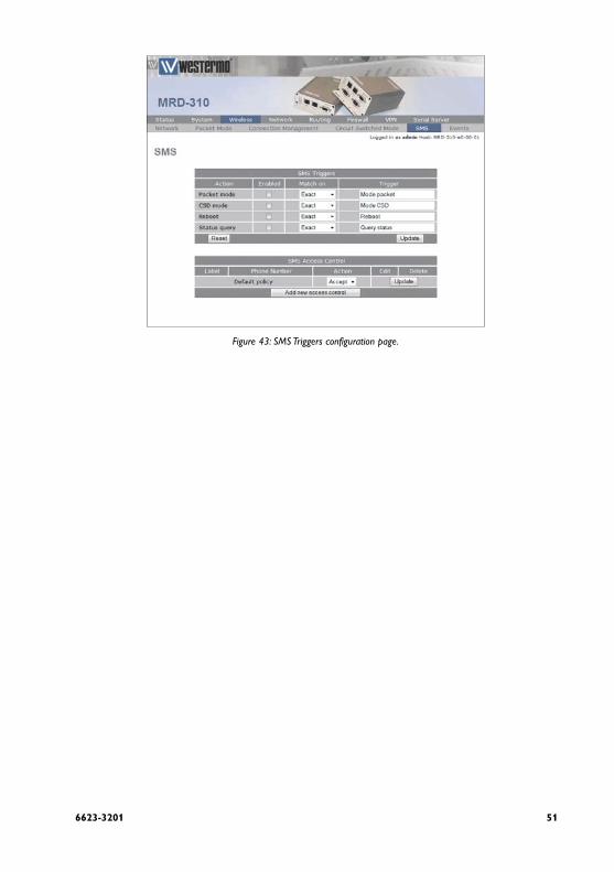
The MRD-3xx provides SMS triggers which can be used to change the Wireless operating mode, reboot the unit and request a status summary. Each SMS trigger can individually be enabled and disabled and the text trigger can be defined for each trigger. Access control is provided to control what numbers have access to the SMS triggers.
3.5.1 Trigger configuration
To access the SMS Triggers select the Wireless tab from the main menu and the SMS tab from the sub-menu. A page simi-lar to that of Figure 43 will be displayed. To configure the trig-gers complete the following steps:
1. For each of the triggers to be enabled, tick the Enabled checkboxes.
2. For each of the triggers to be disabled, untick the Enabled checkboxes.
3. For each of the triggers that has been enabled set the Match on field to:
(a) Exact: The received text must exactly match the Trigger string, any additional characters will cause a mis-match.(b) Contains: The received text must contain the Trigger string, additional characters can be received.(c) Start with: The received text must start with the Trigger string, no additional characters can be received before the Trigger string.
4. For each of the enabled triggers set the Trigger string to the desired text.
5. Click the Update button to save the changes.
516623-3201
Figure 43: SMS Triggers configuration page.

52 6623-3201
3.5.2 Access Control
The SMS Access Control allows fine control over the access to the SMS triggers. The default policy can be set to allow which will allow any number that has not be specifically set to be denied, or the default policy can be set to deny in which case all numbers will be denied unless specifically set to allow.

536623-3201
3.5.2.1 Example: Default policy acceptTo set the SMS Access Control for a default action of allow and to specifically block a number, refer to Figure 43.
and complete the following steps:
1. Click the Add new access control button.
2. In the section titled Add new SMS access control:
(a) Add a label for the new entry.
(b) Enter the phone number.
(c) Set the Action to Drop.
3. Click the Update button to save the changes.
4. Repeat the steps above to add further numbers.
When complete the page will include the number to be dropped, as shown in Figure 44.
44.Figure 44: SMS Triggers number to drop added.

54 6623-3201
3.5.2.2 Example: Default policy to Drop
To set the SMS Access Control for a default action of drop and to specifically accept a number, refer to Figure 45 and complete the following steps:
1. In the section titled SMS Access Control set the Default policy Action to Drop.
2. In the section titled Add new SMS access control:
(a) Add a label for the new entry.(b) Enter the phone number.(c) Set the Action to Accept.
3. Click the Update button to save the changes.
4. Repeat the steps above to add further numbers.
When complete the page will include the number to be accepted, as shown in Figure 46.
Figure 45: SMS Triggers accept entry.

556623-3201
Figure 46: SMS Triggers number to accept added

56 6623-3201
4 Network
This section describes the confiuration of the Network or LAN settings. This includes setting the IP Address of the MRD-3xx Unit, configuring the DHCP server and the DNS settings.
4.1 LAN Interface
The LAN Interface refers to the two switched Ethernet ports located on the front of the MRD-3xx. To access the LAN Interface settings select the Network tab from the main menu then the LAN tab from the sub-menu.
4.1.1 Changing the IP Settings of the LAN Interface
The LAN IP address is the address used to access the MRD-3xx via the LAN (Ethernet) interface. The default IP settings of the MRD-3xx Unit / Router are:
IP Address: 192.168.2.200•Netmask: 255.255.255.0•
The Network settings are contained on the Network / LAN page under the Interface Configuration heading. To change the IP settings :
1. Click the Network tab on the main menu, this will display the LAN page as shown in Figure 47, the LAN interface settings are in the section titled Interface Configuration.
2. Ensure that Enabled is set to Yes.
3. Enter the IP address in the IP Address box.
4. Enter the Netmask in the Netmask box, to that of the sub-net to which the unit is connected.
5. Click the Update button at the bottom of the page to com-mit the changes.

576623-3201
Figure 47: LAN Interface configuration.
Note: Once the IP Address has been changed the new IP address will need to entered into the web browser to re-gain access the MRD-3xx web interface, it will also be necessary to login again. For details on accessing the web pages and logging into the MRD-3xx refer to the User Guide.

58 6623-3201
4.1.2 Disabling the LAN Interface
By default the LAN interface is enabled. The LAN interface can be disabled if the LAN ports are not required.
Note: If the LAN ports are disabled then access to the web configuration pages will only be available via the wireless inter-face if the the Firewall settings allow access to the Web Server, for details on the Firewall configuration refer to Section 5. To re-enable the LAN ports without accessing the Web interface, it will be necessary to perform a factory reset of the MRD-3xx as described in the User Guide, this will clear all the configuration settings of the MRD-3xx to the factory default settings and the LAN ports will be enabled.
To disable the LAN Interface :
1. Click the Network tab on the main menu, this will display the LAN page as shown in Figure 47 the LAN interface settings are in the section titled Interface Configuration.
2. Untick Enabled checkbox.
4. Click Ok.
5. Click the Update button at the bottom of the page to com-mit the changes.
The LAN interface will now be disabled, if the connection to the MRD-3xx was via the LAN ports, a page error may now be indicated.

596623-3201
4.2 DHCP Server Configuration
The DHCP server allows clients on the local network to be automatically allocated IP addresses from the MRD-3xx. The MRD-3xx will also provide the clients with network settings like their default route and DNS servers.
By default the DHCP server is disabled however it has been configured to serve IP addresses in the range 192.168.2.210 through 192.168.2.240, and the Default and Maximum lease times have been set to 1440 minutes. So if these values are consitant with the network that the MRD-3xx is connected to, then the DHCP can be enabled by setting the Enabled field to Yes and clicking the Update button.
Figure 49: DHCP configuration.
If the standard settings are not applicable for the connected network, then refer to Figure 49 and follow the steps below, to configure the DHCP server:
1. Click the Network tab on the main menu, this will display the LAN page as shown in Figure 49, the DHCP settings are in the section titled DHCP Server Configuration.

60 6623-3201
2. Choose a group of available IP addresses on the local network. For example, if the IP address of the MRD-3xx is 192.168.2.200 with a netmask of 255.255.255.0, a group cho-sen could be 192.168.2.100 to 192.168.2.199. This will provide 100 addresses for clients.
3. Tick the Enabled checkbox.
4. Enter the first address of the group in the Start Address box.
5. Enter the last address of the group in the End Address box.
6. Enter a lease time for the Default Lease time.
7. Enter a lease time for the Maximum Lease time.
8. Click the Update button to commit the changes.
4.3 Configuring clients to use the MRD-3xx
The MRD-3xx will act as a gateway for connections destined over the wireless interface. The default configuration will pro-vide Network Address Translation (NAT) and firewalling to protect clients on the local network.
To configure clients to use the MRD-3xx as a gateway:
If the clients have a DHCP address allocated by the •MRD-3xx, they will have learned the necessary set-tings. No further configuration is needed.If clients have static IP addresses, set the default •route and DNS server to the IP address of the MRD-3xx.

616623-3201
4.4 Domain Name System (DNS)
The Domain Name System (DNS) is used to resolve domain names to IP addresses. When connecting to a wireless net-work the MRD-3xx normally receives the IP address of a DNS server to use for DNS requests. The MRD-3xx supports DNS proxy, Manual DNS Configuration and a Dynamic DNS client. The features can be accessed by selecting Network from the main menu and then DNS from the sub-menu. The DNS set-tings page is shown as in Figure 50.
Figure 50: Domain Name Service (DNS) configuration.
4.4.1 DNS Proxy
The MRD-3xx is configured by default to act as a Domain Name Server (DNS) proxy, this means that the MRD-3xx passes DNS requests from the LAN interface to an external DNS server, and returns the result to the client which initi-ated the DNS request. Therefore all devices connected to the LAN Interface can specify the IP address of the MRD-3xx as the DNS server. If the DHCP server of the MRD-3xx has been enabled, then any device that is connected to the LAN interface and requests an IP address via DHCP will automatically be given the IP address of the MRD-3xx as the DNS server.
Set to "Yes" to enable DNS client
Set the DNS service
Enter the DNS domain address
Enter DNS client username
Enter DNS client password
Click "Update" to save changes

62 6623-3201
4.4.2 Manual DNS Configuration
The manual DNS configuration is used to select a DNS server other than the one automatically supplied by the wireless net-work. To configure the manual DNS :
1. Enter an IP address for the primary DNS server in the Primary DNS Server box.
2. Optionally enter the IP address for a secondary DNS server in the Secondary DNS Server box.
3. Enter the DNS domain in the DNS Domain box.
4. Click the Update button at the bottom of the page to com-mit the changes.
The MRD-3xx will now use the DNS Server at the supplied IP addresses for all DNS requests.
4.4.3 Dynamic DNS Client Configuration
Dynamic DNS is a system which allows the domain name data held in a name server to be updated in real time. The most common use for this is in allowing an Internet domain name to be assigned to a device with a dynamic IP address. Depending on the system used by the wireless provider the MRD-3xx may receive a dynamic IP address, using this service it may be possible to establish connections to the MRD-3xx without needing to track the IP address of the MRD-3xx. This makes it possible for other sites on the Internet to establish connections to the machine without needing to track the IP address themselves.
Note: Some service providers do not allow access to dynam-ic IP address, so even though the Dynamic DNS client will connect and register the IP address provided to the MRD-3xx unit, all attempts to connect to that IP address will fail.
In order to use the Dynamic DNS feature of the MRD-3xx you will first need to register at a Dynamic DNS provider, the MRD-3xx supports the follwoing providers:
Drop-down option Provider
dyndns.com http://www.dyndns.com/
no-ip.com http://www.no-ip.com/
zoneedit.com http://zoneedit.com/
easydns.com http://www.easydns.com/

636623-3201
Once registration is complete follow the steps below to configure the MRD-310/330, for reference Figure 51 show an example configuration.
1. Click the Network tab on the main menu, then select DNS from the sub-menu, this will display the DNS page, the Dynamic DNS settings are in the section titled Dynamic DNS Client Configuration.
2. Tick Enabled checkbox.
3. Select the service provider from the Service drop-down menu.
4. Enter the Domain in the Domain text box.
5. Enter the username for your account in the Username text box.
6. Enter the password for your account in the Passoword text box.
7. Click the Update button to save the changes.
Figure 51: Dynamic Domain Name Service (DNS) Client configuration.

64 6623-3201
5 Firewall
The MRD-3xx has a Stateful Packet Inspection (SPI) Firewall that controls the connections from the wireless port to the LAN ports and to the unit itself. The firewall can be used to limit the connections that can be established to or via the unit. For example, if the unit is only to be used for serial communications then the firewall can be set-up to only allow connections through to the serial server (which connects to the serial ports).
5.1 Firewall Setup
The MRD-3xx firewall configuration is accessed by selecting the Firewall tab from the main menu. When selected the page shown in Figure 52 will be displayed. This page shows and allows configuration of the basic settings for the firewall.
Figure 52: Basic firewall conguration.

656623-3201
5.1.1 Network Address and Port Translation (NAPT)
As connection pass from the LAN network out the wire-less port, the firewall can perform Network Address and Port Translation (NAPT). When set, this option will cause the fire-wall to substitute the address of the wireless port for the source address of connections received from the LAN net-work. This is most useful where the LAN network is a private network but the wireless port has a public address.In some cases, for example, if connected to an IP WAN that supports direct routing to the LAN network of the unit, it may be desirable to disable the NAPT function. This will allow clients on the LAN to be directly addressed without the need for port forwards. To disable NAPT, uncheck the Connections from LAN checkbox and press Update.
5.1.2 Stateful Packet Inspection (SPI)
The firewall in the unit can function in Stateful Packet Inspection (SPI) mode. When enabled, the firewall will track the state of each connection passing through it (for example, TCP streams) and only allow packets belonging to a known connection to enter from the wireless port. In most cases, SPI should be enabled for greater security. When disabled, the fire-wall will allow all incoming packets from the wireless port to be forwarded through to the LAN network.
In some cases, for example, if connected to an IP WAN that supports direct routing to the LAN network of the unit, it may be desirable to disable the SPI function. This will allow clients on the LAN to be directly addressed without the need for port forwards. To disable SPI, uncheck the Accept only established destined to LAN checkbox and press Update.

66 6623-3201
5.1.3 Connection tracking options
The firewall can be configured to optionally provide connec-tion tracking and NAT support for a number of additional protocols. The protocols are listed in Table 1.To enable support for a protocol, click the checkbox for the protocol and press Update.
Protocol Description
FTP Adds support for active mode File Transfer Protocol
TFTP Adds support for the Trivial File Transfer Protocol
H.323 Adds support for the H.323 voice and videocon-ferencing protocol
PPTP Adds support for the Point-to-point Tunneling Protocol
IRC Adds support for the Internet Relay Chat pro-tocol
Table 1Firewall Connection tracking options
676623-3201
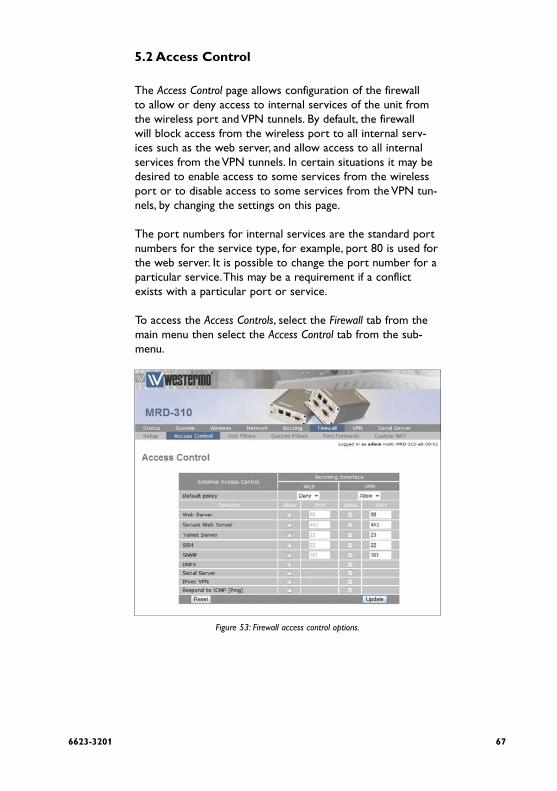
5.2 Access Control
The Access Control page allows configuration of the firewall to allow or deny access to internal services of the unit from the wireless port and VPN tunnels. By default, the firewall will block access from the wireless port to all internal serv-ices such as the web server, and allow access to all internal services from the VPN tunnels. In certain situations it may be desired to enable access to some services from the wireless port or to disable access to some services from the VPN tun-nels, by changing the settings on this page.
The port numbers for internal services are the standard port numbers for the service type, for example, port 80 is used for the web server. It is possible to change the port number for a particular service. This may be a requirement if a conflict exists with a particular port or service.
To access the Access Controls, select the Firewall tab from the main menu then select the Access Control tab from the sub-menu.
Figure 53: Firewall access control options.

68 6623-3201
5.2.1 Accessing unit services from the wireless port or VPN tunnels
The External Access table on the Access Control page is shown in Figure 53. It controls which services can be accessed from the wireless port and VPN tunnels. By default, the unit will block all requests received on the wireless port and allow all requests received from VPN tunnels.
There are several modes for determining which services can be accessed:
No access
All incoming requests are dropped. Set the Default policy set to Deny and check no boxes in the Allow column.
Restricted access
Incoming requests for particular services will be allowed. Set the Default policy to Deny and check the boxes for the desired services in the Allow column.
Full access
All incoming requests allowed. Set the Default policy to Allow.
To change the port number that a service is received on, change the entry in the Port column for the given service. For example, to change the web server to port 8080 on the wire-less port, enter 8080 in the WLS column on the Web Server row.

696623-3201
5.3 DoS Filters
A denial of service attack (DoS attack) is an attempt to render a network device unavailable to intended users. The most common method of attack involves saturating the target device with external communications requests, such that it cannot respond to legitimate traffic, or responds so slowly as to be rendered effectively unavailable. The intention of DOS attacks is to cause the targeted device to reset or consume resources to such a level that it is unable to provide the intended service. A consequence of such an attack is that even if the device is able to handle the large number of communica-tions requests, the bandwidth over the communications chan-nel used for the attack may be completely consumed, poten-tially preventing legitimate connections to the targeted device.
The firewall has filters that can detect and drop packets that may be part of a Denial of Service (DOS) attack, for example, TCP packets with invalid header information. Options to ena-ble and disable these filters can be found on DoS Filters page.

70 6623-3201
5.3.1 Enabling the Denial of Service filters
The Filter Description table provides a number of DOS filters, as shown in Figure 54. The filters can be applied to packets received from the LAN port, the wireless port (WLS), and from any VPN tunnel by checking the boxes in the appropriate column.
Figure 54: Firewall DoS filter options.
The function of each filter is described below:
Rate limit TCP SYN packets
This will limit the number of new TCP connection requests (SYN packets) allowed from the given interface. The rate will be limited to 5 per second.
Drop invalid TCP flag combinations
Some DOS attacks will send packets that present an invalid combination of TCP flags which may cause problems for some operating systems. The filter will drop packets with invalid combinations received on the given interface.
Rate limit ICMP requests
This will limit the number of ICMP requests (for example, ping requests) allowed from the given interface. The rate will be limited to 5 per second.
Accept limited ICMP types
The types of ICMP packets that are accepted will be limited to types 0, 3, 8 and 11.

716623-3201
5.4 Custom Filters
5.4.1 Description
Custom Filters allow new rules to be added to the firewall to allow or deny specific packets. Packets can be matched based on which of the unit's network interfaces they arrive on or will leave on, the protocol, the source or destination address.
Some example custom filters are:
A filter than only allows traffic from a particular host on • the WAN to access through to the LAN ports.A filter that drops all traffic from a particular host on the • WAN.
To select the Custom Filters page click the Custom Filters tab on the sub-menu. Figure 55 shows the custom filter page with no filters configured.
Figure 55: Custom Filter main page with no filters configured.
72 6623-3201
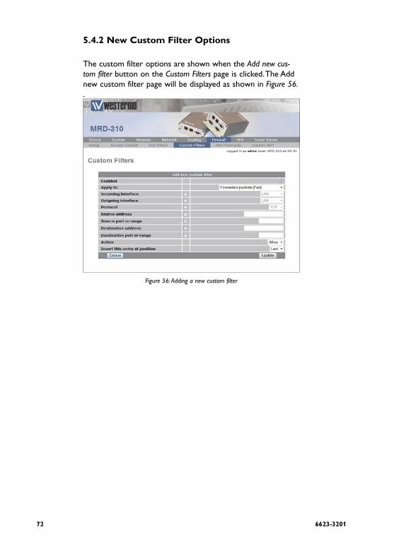
5.4.2 New Custom Filter Options
The custom filter options are shown when the Add new cus-tom filter button on the Custom Filters page is clicked. The Add new custom filter page will be displayed as shown in Figure 56..
Figure 56: Adding a new custom filter

736623-3201
The following options can be set for each custom filter:
Enabled
Set the Enabled check box to have the rule installed in the firewall. A rule can be temporarily disabled by unchecking this box.
Apply to
Custom filters can be applied at three separate points in the unit:
Forwarded packets. • The filter will be applied to packets that are received from one network interface and then routed out another network interfaceLocally destined packets. • The filter will be applied to packets destined for the unit's internal services.Locally generated packets. • The filter will be applied to packets generated by one of the unit's internal services.
Incoming interface
If selected, packets will be matched based on the network interface they have been received on. Note that this can't be applied to Locally generated packets as they have been gener-ated by the unit itself.
Outgoing interface
If selected, packets will be matched based on the network interface they will be transmitted on. Note that this can't be applied to Locally destined packets as they will be received by the unit itself.
Protocol
If selected, packets will be matched based on their protocol type. Note that if you wish to match on source or destination ports, the protocol must be set to TCP or UDP.

74 6623-3201
Source address
If selected, either a single address (for example, 172.16.1.132) or a subnet range (for example, 172.16.0.0/24) can be entered. Only packets matching this source address will have the filter applied to them.
Source port or range
If selected, packets will be matched based on their TCP or UDP source port. Either an individual port (for example, 443) or a range of ports (80-143) can be entered.
Destination address
Similar to the Source address, but instead matching on the destination address.
Destination port or range
Similar to the Source port or range, but instead matching on the destination port.
Action
Determines what action on packets who meet all of the matching criteria for the filter. If set to Deny, the packet will be dropped. If set to allow, the packet will be passed.
Insert this entry at position
Determines where this entry will be inserted in the list of custom filters.

756623-3201
5.4.3 Adding a new custom filter
From the main Custom Filters page click the Add new custom filter button. This will select the Add new custom filter page. An example of adding a new custom filter is shown in Figure 57. In this example, a new filter will be created to allow packets received via the wireless port, from IP address 112.112.112.112 and destined to the LAN network.
Figure 57: Adding a new custom filter.
As shown in the example that in the centre column, Incoming interface, Outgoing interface and Source address are checked. This indicates that these are the matching criteria that will be applied to packets. All criteria that are unchecked will be ignored.

76 6623-3201
To save the new filter click the Update button. The main Custom Filter page will again be shown with the new filter listed, as shown in Figure 58.
Figure 58: The custom filter page with a single filter.

776623-3201
To add a second filter, again click the Add new custom filter button. In the example shown in Figure 59, a custom filter is created which will deny packets received from the LAN port, from IP address 211.211.211.211 and destined to the wire-less network. Again notice that in the centre column, Incoming interface, Outgoing interface and Source address are checked. This indicates these are the matching criteria that will be applied to packets. All criteria that are unchecked will be ignored.
Figure 59: Adding a new custom filter

78 6623-3201
To add the filter to the filters table click the Update button, the main page will again be shown with the new filter added, as seen in Figure 60.
Figure 60: The custom filter table with 2 filters.

796623-3201
5.4.4 Editing a Custom Filter
A custom filter can be edited by clicking the pencil icon in the Edit column of the filter to be changed. Once clicked, the details of the filter will display in the same table as shown when adding a new filter.
As an example, to edit the second filter, click the pencil icon in the second row of the table. A page similar to the Add new fil-ter page will be displayed, but now showing the details of filter 2. Changes that add protocol and port number matching to the criteria are shown in Figure 61..
Figure 61: Editing a custom filter.

80 6623-3201
To save the changes click the Update button or to lose any changes click the Cancel button. The main page will again be displayed as shown in Figure 62, with the changes for filter 2 added to the table.
Figure 62: The main custom filter table after editing filter 2.
816623-3201
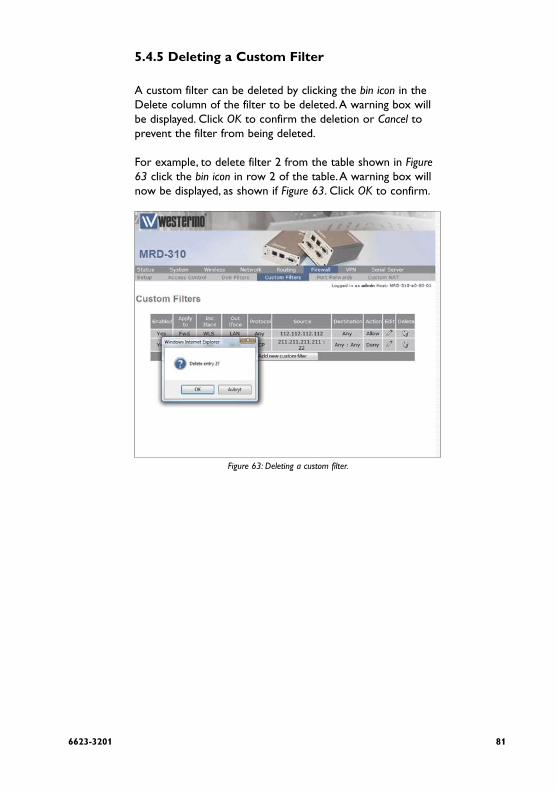
5.4.5 Deleting a Custom Filter
A custom filter can be deleted by clicking the bin icon in the Delete column of the filter to be deleted. A warning box will be displayed. Click OK to confirm the deletion or Cancel to prevent the filter from being deleted.
For example, to delete filter 2 from the table shown in Figure 63 click the bin icon in row 2 of the table. A warning box will now be displayed, as shown if Figure 63. Click OK to confirm.
Figure 63: Deleting a custom filter.

82 6623-3201
The filter table will be displayed with the filter removed, as shown in Figure 64.
Figure 64: Custom filter table with filter 2 removed.

836623-3201
5.5 Port Forwarding
Port forwarding rules alter the destination address (and optionally the destination port) of packets received on the wireless port or VPN interfaces of the unit. Port forwards can be used to forward specific services (eg HTTP) to a private machine on the LAN network without needing to expose the entire private machine to the public network.
To access the port forward configuration page, select the Firewall tab from the main menu, then the Port Forwards tab from the sub-menu. The page will list a table showing all cur-rent port forwards. When first selected the table will be empty as shown in Figure 65
Figure 65: Port forward page with no port forwards configured.

84 6623-3201
5.5.1 Port Forward Options
To access the port forward options click the Add new port for-ward button on the main port forwards page. Figure 66 shows the page for entering a new forward.
Figure 66: Page to add a Port forward.
The following options can be set for each port forward:
Enabled
Set the enabled check box to have the rule installed in the firewall. A rule can be temporarily disabled by unchecking this box.
Protocol
The unit is able to forward TCP, UDP, GRE, ESP and AH. Most forwards will be either TCP or UDP. Select the appropriate protocol from the list.
Incoming interface
Select the interface that the packets to be forwarded on will arrive (in this case, WLS, the wireless port, is selected).

856623-3201
Source address
For greater security, the source addresses that the forward will be applied to can be limited. In this field, either a single address (for example, 172.16.1.132) or a subnet range (for example, 172.16.0.0/24) can be entered.
Original destination port or range
This is the port number (80 in the example) but can also be a range (entered as, for example, 120-150) that the firewall will match on to forward to the new destination address.
New destination address
This is the IP address of the server to forward to (192.168.2.230 in the example).
New destination port
In addition to changing the destination address, it is also pos-sible to change the destination port. To do so, enter the port in this field. This field can be left blank to keep the port the same.
Insert this entry at position
Determines where this entry will be inserted in the list of port forwards.

86 6623-3201
5.5.2 Adding a new port forward
From the main port forwards page, click the Add new port forward button. This will select the Add new port forward page. An example of adding a new port forward is shown in Figure 67. In this example a new port forward is created to forward from port 80 of the wireless port to a HTTP server at address 192.168.2.240.
Figure 67: Adding a Port forward.

876623-3201
Click Update to save the new port forward. The port forward table will be updated to include the new port forward as shown in Figure 68.
Figure 68: The port forward page with a single port forward.
To add a second port forward click the Add new port forward button. In the example shown in Figure 69, a port forward is created which forward packets received for IP address 112.112.112.112 on port 80 of the wireless port to LAN IP address 192.168.2.232.
Figure 69: Adding a second port forward

88 6623-3201
To add the new port forward to the port forward table click the Update button. The main page will again be shown with the new port forward added, as seen in Figure 70.
Figure 70: The port forward page with a two port forwards.
896623-3201
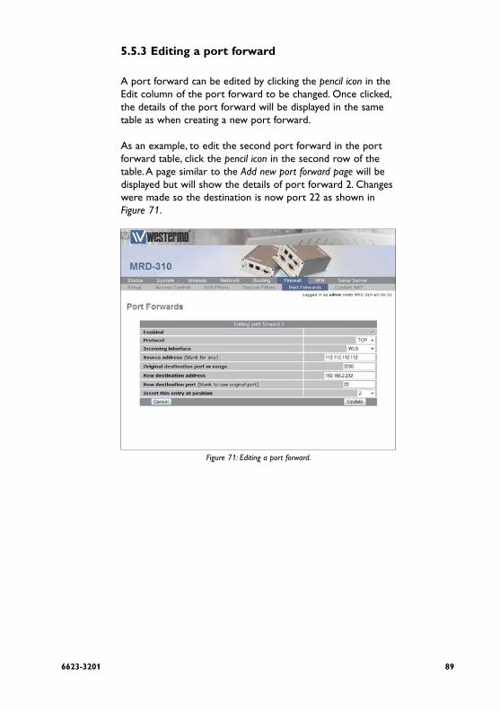
5.5.3 Editing a port forward
A port forward can be edited by clicking the pencil icon in the Edit column of the port forward to be changed. Once clicked, the details of the port forward will be displayed in the same table as when creating a new port forward.
As an example, to edit the second port forward in the port forward table, click the pencil icon in the second row of the table. A page similar to the Add new port forward page will be displayed but will show the details of port forward 2. Changes were made so the destination is now port 22 as shown in Figure 71.
Figure 71: Editing a port forward.

90 6623-3201
To save the changes, click the Update button or to lose changes click the Cancel button. The main page will again be displayed as shown in Figure 72, with the changes for port for-ward 2 added to the table.
Figure 72: Main port forward page with revised port forward.

916623-3201
5.5.4 Deleting a port forward
A port forward can be deleted by clicking the bin icon in the Delete column of the forward to be deleted. A warning box will be displayed. Click OK to confirm the deletion.
For example, to delete port forward 2 from the table shown in Figure 72, click the bin icon in row 2 of the table. A warning box will now be displayed as shown if Figure 73. Click OK.
Figure 73: Deleting a port forward.

92 6623-3201
The port forward table will be displayed with the port for-ward removed, as shown in Figure 74.
Figure 74: Port forward table of deleting a port forward

936623-3201
5.6 Custom NAT
5.6.1 Description
Custom NAT allow new rules to be added to the firewall to carry out Network Address Translation (NAT) that is differ-ent to the usual NAT provided by the firewall. Packets can be matched based on which of the unit's network interfaces they arrive on or will leave on, the protocol, the source or destination address. The packets can have Source-NAT (SNAT) applied, where the source address is altered, or Destination-NAT (DNAT) applied, where the destination address is altered.
Some example custom NATs are:
Source-NAT on all packets being transmitted out a • VPN tunnel. Destination-NAT to redirect packets to a host on the LAN.
To access the Custom NAT configuration page, select the Firewall tab from the main menu, then the Custom NAT tab from the sub-menu. The page will list a table showing all current custom NATs. When first selected the table will be empty as shown in Figure 75.
Figure 75: Main custom NAT page, with no custom NAT entries in the table.

94 6623-3201
5.6.2 Custom NAT Options
To access the Custom NAT options click the Add new custom NAT button on the main Custom NAT page. Figure 76 shows the page for entering a custom NAT.
Figure 76: Add new Custom NAT page.

956623-3201
The following options can be set for each custom NAT:
Enabled
Set the enabled check box to have the rule installed in the firewall. A rule can be temporarily disabled by unchecking this box.
NAT Type
Determines the type of NAT the entry will perform.
Apply to
When entering a destination NAT, there are two places the NAT can be applied:
Incoming packets • The rule will be applied to packets received from the unit's network interfaces.
Locally generated packets • The rule will be applied to packets generated by one of the unit's internal services.
Incoming interface
If selected, packets will be matched based on the network interface they have been received on. Note that this can only be applied to a Destination NAT on Incoming packets.
Outgoing interface
If selected, packets will be matched based on the network interface they will be transmitted on. Note that this can only be applied to a Source NAT.
Protocol
If selected, packets will be matched based on their protocol type. Note that if you wish to match on source or destination ports, the protocol must be set to TCP or UDP.
Source address
If selected, either a single address (for example, 172.16.1.132) or a subnet range (for example, 172.16.0.0/24) can be entered. Only packets matching this source address will have the filter applied to them.

96 6623-3201
Source port or range
If selected, packets will be matched based on their TCP or UDP source port. Either an individual port (for example, 443) or a range of ports (80-143) can be entered.
Destination address
Similar to the Source address, but instead matching on the destination address.
Destination port or range
Similar to the Source port or range, but instead matching on the destination port.
Target address
This is the address that the NAT rule will apply to packets. When set to Custom, any IP address can be entered in the text box. If an interface is selected from the dropdown box, the current address of that interface will be applied to packets.
Target port
For rules that specify either the TCP or UDP protocol, it is possible to also alter the port number. If no change of port number is desired, this field can be left blank.
Insert this entry at position
Determines where this entry will be inserted in the list of custom NAT rules.

976623-3201
5.6.3 Adding a new custom NAT
From the main port forwards page click the Add new custom NAT button. This will select the Add new custom NAT page. An example of adding a new custom NAT is shown in Figure 77. In this example, a new custom NAT is created which will source NAT packets outgoing on the SSL VPN interface to the IP address of the SSL VPN.
Figure 77: Adding a custom NAT.
It can be seen in the example that in the centre column only Outgoing interface is checked. This indicates these are the matching criteria that will be applied to packets. In this case, all packets outgoing on the SSL VPN will be source NAT'd.

98 6623-3201
Click Update to save the new custom NAT. The custom NAT table will be updated to include the new custom NAT as shown in Figure 78.
Figure 78: Main custom NAT page showing new custom NAT added to the table.

996623-3201
To add a second custom NAT again click the Add new custom NAT button. In the example shown in Figure 79, a destination NAT is created for packets destined for the wireless port.
Figure 79: Adding a custom NAT.
To add the new custom NAT click the Update button. The main page will again be shown with the new custom NAT added, as seen in Figure 80.
Figure 80: Main custom NAT page showing new custom NAT added to the table.
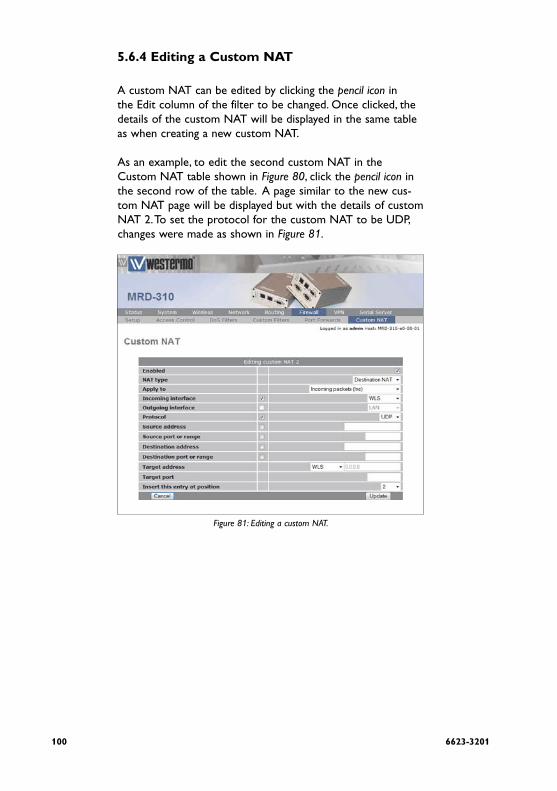
100 6623-3201
5.6.4 Editing a Custom NAT
A custom NAT can be edited by clicking the pencil icon in the Edit column of the filter to be changed. Once clicked, the details of the custom NAT will be displayed in the same table as when creating a new custom NAT.
As an example, to edit the second custom NAT in the Custom NAT table shown in Figure 80, click the pencil icon in the second row of the table. A page similar to the new cus-tom NAT page will be displayed but with the details of custom NAT 2. To set the protocol for the custom NAT to be UDP, changes were made as shown in Figure 81.
Figure 81: Editing a custom NAT.

1016623-3201
To save the changes click the Update button or to lose the changes click Cancel. The main page will again be displayed as shown in Figure 82, with the changes for custom NAT 2 added to the table.
Figure 82: Main custom NAT page with revised custom NAT 2.

102 6623-3201
5.6.5 Deleting a Custom NAT
A custom NAT can be deleted by clicking the bin icon in the Delete column of the NAT to be deleted. A warning box will be displayed. Click OK to confirm the deletion.
For example, to delete custom NAT 2 from the table shown in Figure 82, click the bin icon in row 2 of the table. A warning box will now be displayed as shown if Figure 83. Click OK.
Figure 83: Deleting a Custom NAT.

1036623-3201
The custom NAT table will be displayed with the custom NAT removed, as shown in Figure 84.
84.Figure 84: Custom NAT table after deleting a Custom NAT.

104 6623-3201
6 Virtual Private Network (VPN)
A virtual private network (VPN) is a communications network tunneled through another network, in the case of the MRD-3xx unit the secured communications network is tunneled through the 3G wireless network and then over the Internet or private network to a VPN capable router or server. The MRD-3xx unit has support for SSL, IPsec and PPTP/L2TP based VPNs and can be configured for multiple VPN tunnels to operate simultaneously.

1056623-3201
6.1 Secure Sockets Layer (SSL) VPN.
Secure Sockets Layer (SSL), are cryptographic protocols that provide secure communications over a communications net-work. SSL operates at the transport layer, layer 4 of the OSI model, this means that it is can be used to create a tunnel through which other layer 4 protocols such as TCP & UDP can pass.
An example of an SSL VPN is OpenVPN which is a free and open source virtual private network (VPN) program for creat-ing point-to-point or server-to-multiclient encrypted tunnels. It is capable of establishing direct links between computers that are behind NAT firewalls. For information on installing and configuring OpenVPN refer to the OpenVPN website: http://openvpn.net/

106 6623-3201
6.1.1 SSL VPN Configuration
To access the SSL VPN configuration page, select VPN on the main menu, the SSL VPN configuration page is the first option on the sub-menu so it will be automatically displayed. Figure 85 shows the MRD-3xx SSL based VPN configuration options available.
Figure 85: SSL based VPN configuration web page.
The configuration options are dived into Basic Configuration in the top part of the page and Advanced Configuration in the bottom section of the page. The details of each option is described below:

1076623-3201
Basic Configuration options
Enabled Check the box to enable the SSL VPN.
Connection ProtocolDropdown box to select the connection protocol, either TCP or UDP (default).
Transport TypeSelect the transport type from either routed (default) or bridged mode.
Bridged • Bridging is a technique for creating a virtual, wide-area Ethernet LAN, running on a single subnet. The advantages of bridging are broadcasts will traverse the VPN which in some situations is desirable, and no routing rules are required. The disadvantages are broadcasts can be problematic on a wireless network as the over-the-air traffic is increased and bridging does not scale well as new devices are added to the network.
Routed • Routing will create a separate sub-net for each VPN connection, to access one subnet from another requires routing rules to be configured at the VPN router. The advantages of routing are efficiency, scaleability and no broadcast traffic, this is particularly important with wireless networks to reduce the over-the-air traffic. The disadvan-tage is that routing rules are required which adds to the configuration.
Remote address Specify the address of the remote VPN server.
Remote portSpecify the port number of the remote VPN server.

108 6623-3201
CertificateSpecify the certificate to use for authentication. For details on how to load certificates refer to Section 6.5 Certificate Management.
Advanced Configuration options
Ping interval (secs)Specify the interval in seconds at which to Ping the remote server. This is used to determine the status of the connection.
Ping timeout (secs)Specify the ping timeout in seconds. This is used to determine if the VPN connection has terminated, if this time is exceeded the connection will be re-established.
CompressionSpecify if compression is to be used for the data being trans-mitted through the VPN tunnel. Select one of the following options from the drop-down list:
Off • Compression is disabled.
Adaptive • The performance will be measured with com-pression on and with compression off, the option with the higher performance will be selected.
On • Compression is enabled.

1096623-3201
Encryption algorithm Specify the encryption algorithm to use from the drop-down list, the options are:
DES • Data Encryption Standard.
3DES (192) • 192 bit Triple Data Encryption Standard.
Blowfish (128) • 128 bit Blowfish (Default).
AES (128) • 128 bit Advanced Encryption Standard (AES).
AES (192) • 192 bit Advanced Encryption Standard (AES).
AES (256)• 256 bit Advanced Encryption Standard (AES).

110 6623-3201
6.1.2 Connecting to a VPN Server
An example of connecting to a VPN server will be described. Figure 86 illustrates the network which will be established. For this example a connection will be established from the MRD-3xx to an OpenVPN server using a routed connection and UDP as the connection protocol. The IP address of the OpenVPN server is 123.123.123.123 and the port number is 1194. The certificate supplied for authentication is called demoClient. To ensure the connection remains connected the ping interval will be set to 30 seconds with a timeout of 120 seconds. Compression will be disabled and the Encryption algorithm will 128 bit Blowfish.
Figure 86: SSL based VPN example network.

1116623-3201
Select VPN on the main menu, to display the the SSL VPN con-figuration page. Figure 87 shows the MRD-3xx SSL based VPN configuration with the options set for the example.
Figure 87: SSL based VPN configuration web page.
The following are configuration settings used for the example:

112 6623-3201
Basic Configuration options
Enabled: Checked
Connection Protocol: UDP
Transport Type: Routed
Remote address: 123.123.123.123
Remote port: 1194
Certificate: demoClient
Advanced Configuration options
Ping interval (secs): 30
Ping timeout (secs): 120
Compression: Off
Encryption algorithm: Blowfish (128)

1136623-3201
Once the configuration has been completed click the Update button to save the changes. The SSL VPN will now be started and it will attempt to establish a connection with the VPN server specified. The status of the VPN can be checked on the VPN status page, to access this page click Status on the main menu then VPN on the sub-menu, a page similar to that shown in Figure 88 will be shown. This page indicates that the VPN is connected and lists the local IP address.
Figure 88: SSL VPN status page.
In order to test the VPN a ping command can be run from a machine connected to the VPN server, the following is the result of the ping:
$ ping 10.90.91.30
PING 10.90.91.30(10.90.91.30) 56(84) bytes of data.
64 bytes from 10.90.91.30: icmp_seq=1 ttl=62 time=141 ms
64 bytes from 10.90.91.30: icmp_seq=2 ttl=62 time=122 ms
64 bytes from 10.90.91.30: icmp_seq=3 ttl=62 time=120 ms
64 bytes from 10.90.91.30: icmp_seq=4 ttl=62 time=121 ms
64 bytes from 10.90.91.30: icmp_seq=5 ttl=62 time=121 ms
64 bytes from 10.90.91.30: icmp_seq=6 ttl=62 time=122 ms
64 bytes from 10.90.91.30: icmp_seq=7 ttl=62 time=123 ms
--- 10.90.91.30 ping statistics ---
7 packets transmitted, 7 received, 0% packet loss, time 5998ms
rtt min/avg/max/mdev = 120.620/124.725/141.429/6.867 ms
$

114 6623-3201
The MRD-3xx has responded to the ping and the byte counters on the status page have increased as seen in Figure 89.
Figure 89: SSL VPN status after running Ping, the byte counts have increased.
The VPN is now operational as can be used to pass data.

1156623-3201
6.2 Internet Protocol Security (IPsec) VPN
Internet Protocol Security (IPsec) is a suite of standards and protocols for securing Internet Protocol (IP) communications by authenticating and/or encrypting each IP packet in a data stream. Also include within IP sec are protocols for cryp-tographic key establishment. IPsec protocols operate at the network layer, layer 3 of the OSI model, this means that it can be used for protecting layer 4 protocols, including both TCP and UDP, the most commonly used transport layer protocols. Using strong encryption and public key cryptography IPsec can secure data links over public networks which would otherwise be insecure.
IPsec is a framework which is built in to various security products from companies such as Cisco and Juniper, to pro-vide end-to-end security. The MRD-3xx unit IPsec functionality has been tested for interoperability with the Cisco implemen-tation of IPsec know as Cisco IOS IPsec.

116 6623-3201
6.2.1 General IPsec Configuration
To access the MRD-3xx IPsec VPN configuration page click VPN on the main menu then click IPsec VPN on the sub-menu. The page shown in Figure 90 will be displayed. The page con-tains general IPsec configuration options at the top and a list of configured tunnels at the bottom.
Figure 90: IPsec based VPN main page.

1176623-3201
General IPsec Configuration
EnabledCheck the box to enable the IPsec VPN. Default is disdisabled.
NAT traversal enabled & keepalive period (secs)Check box to enable NAT Traversal and set the keepalive time.
NAT Traversal • When passing through a Network Address Translator (NAT) an IP packet is modified in such a way that is incompatible with Internet Protocol Security (IPsec). NAT-Traversal protects the original IPsec encoded packet by encapsulating it within another layer of UDP and IP headers. If the wireless interface of the MRD-3xx is allocated a dynamic and private IP address then the con-nection to the Internet will be via a Network Address Translator (NAT), this will require the use of NAT-Traversal for IPsec to establish a con-nection.
Keepalive Period • NAT keepalives are used to keep the dynamic NAT mapping alive during a connection between two peers. NAT keepalives are UDP packets with an unencrypted payload of 1 byte. Although similar to dead peer detection (DPD), NAT keep-alives are different, DPD is used to detect peer status, while NAT keepalives are sent if the IPSec entity did not send or receive the packet at a specified period of time.
IPsec MTU Maximum Transmission Unit (MTU) is the size (in bytes) of the largest packet which can be sent over the IPsec tunnel. Leave this value blank to use the default setting.

118 6623-3201
6.2.2 Adding an IPsec Tunnel
To add an IPsec tunnel click the Add new tunnel button, this will display the first of 3 pages used to configure the IPsec VPN tunnel. The first page is the Tunnel Configuration shown in Figure 91, the second page is Phase 1 configuration shown in Figure 92 and the third page is the Phase 2 configuration shown in Figure 93.
Figure 91: IPsec tunnel configuration.

1196623-3201
Tunnel Configuration
IPsec Tunnel configuration is the first stage in adding a new IPsec tunnel. The options are as follows:
Label Set the label or name for the tunnel. This is used as a refer-ence and is particularly useful when more than one tunnel is configured.
EnabledCheck the box to enable the IPsec VPN.
Local interface Select the interface over which to create the tunnel, from the following options:
Default (Default) • The interface to which the default route directs connections.
WLS • The wireless interface.
LAN • The LAN (Ethernet) interface.

120 6623-3201
Local nexthop The nexthop gateway IP address for the connection to the public network. If the local interface is set to default this option will be set to Auto and is not able to be changed. Select one of the following options:
Default • Use default route
Auto (Default) • Use the gateway IP address of the selected local interface.
Custom • Set an IP address.
Remote host IP address or fully qualified domain name of remote host, to which the connection is to be established.
Operating modeSelect the operating mode of the IPsec tunnel, from the fol-lowing options:
Tunnel (Default) • Tunnel mode encapsulates the entire IP packet to provide a secure connection between two gateways. In tunnel mode the payload, the header and the routing information are all encrypted, and then encapsulated into a new IP packet, this mode is generally used to create a VPN.
Transport • Transport mode provides a secure connection between two hosts, only the the payload of the IP packet is encrypted.

1216623-3201
Initiate tunnel Check the box to enable the tunnel initiation. If the wireless IP address is dynamic then this option would normally be enabled.
Init rekeying, margin (mins) & fuzz Rekeying is used to re-negotiated the connection prior to it expiring. The options are:
Init rekeying • Check to enable rekeying. Default is On.
Margin • The time in minutes prior to the connection expiring at which attempts to negotiate a new connection begin. Default is 10 Minutes.
Fuzz • Defines the maximum percentage by which the margin can be increased in order to randomise rekeying intervals. Default is 100%.
Dead peer detection delay & timeout (sec) Dead Peer Detection (DPD) is a method of detecting a dead Internet Key Exchange (IKE) peer. The method uses IPsec traf-fic patterns to minimise the number of messages required to confirm the availability of the connection. The options are:
Delay • Set the delay in seconds between Dead Peer Detection keepalives that are sent for the con-nection.
Timeout • The time in seconds to declare the peer dead after the delay and not receiving data or a keep-alive.

122 6623-3201
Figure 92: IPsec Phase 1 configuration.
Phase 1 Configuration
The Phase 1 Configuration is used to set the parameters for the first phase of IPsec Key Exchange (IKE). The first phase is a set-up phase in which the two hosts agree on how to exchange further information securely.
The options for Phase 1 are:
Authentication method Select the authentication method from the drop-down list, the options are:
Pre-shared key • The Pre-Shared Key (PSK) is a key value which is entered into each host and is used for authentica-tions.
Certificate • A certificate is an electronic document containing a public key and a digital signature.

1236623-3201
Pre-shared key This field is used to enter the Pre-Shared Key if this method of authentication was selected. To enter a new key check the box and enter the key in the text field. During key entry the key will be in clear-text, once the page is updated the key will no longer be visible. The text immediately prior the check-box will indicate if a key has been Set or Not set.
CertificateSelect the certificate to use if Certificate authentication has been selected. For information on how to enter certificates refer to Section 6.5 Certificate Management.
Remote ID The remote host ID.
Local ID The local host ID.
Negotiation modeSelect the negotiated mode from the drop-down list, the options are:
Main mode • Main mode provides identity protection for the hosts initiating the session. Main mode cannot be used when there is Network Address Translation (NAT) on the connection between hosts.
Aggressive mode • Aggressive mode is quicker to establish a con-nection than Main mode but provides no identity protection. Main mode can be used when there is Network Address Translation (NAT) on the con-nection between hosts.

124 6623-3201
IKE proposal A set of parameters for Phase I IPSec negotiations. The param-eters are encryption algorithm, authentication algorithm and the Diffie-Hellman group.
Encryption Algorithm • Select the encryption algorithm from the drop-down list, the options are: AES (128) 128 bit Advanced Encryption Standard (AES). AES (256) 256 bit Advanced Encryption Standard (AES). 3DES Triple Data Encryption Standard (3DES). DES Data Encryption Standard (DES).
Authentication Algorithm • Select the authentication mode from the drop-down list, options are: MD5 Message-Digest algorithm 5. SHA1 Secure Hash Algorithm.
Diffie-Hellman Group • A cryptographic protocol which allows two parties to establish a shared secret key over an insecure network without the parties having any prior knowledge of the other party. Select the Diffie-Hellman Group from the drop-down list, the options are: DH Grp 1 (768) The 768 bit Diffie-Hellman group. DH Grp 2 (1024) The 1024 bit Diffie-Hellman group. DH Grp 5 (1536) The 1536 bit Diffie-Hellman group. DH Grp 14 (2048) The 2048 bit Diffie-Hellman group.
IKE lifetime (mins) Specify the IKE lifetime in minutes. Default is 60 minutes.

1256623-3201
Figure 93: IPsec Phase 2 configuration.

126 6623-3201
Phase 2 Configuration
Phase 2 establishes the IPsec Security Associations (SA) parameters in order to establish an IPsec tunnel. Phase 2 has one mode called Quick mode, it starts after IKE has started a secure tunnel in phase 1. Quick mode is also used to re-negotiate a new IPsec SA when the current IPsec SA lifetime expires.
The phase 2 options are:
ESP proposal Encapsulating Security Payload (ESP) is used to encrypt the data transmitted in IP datagrams. The proposal establishes the Encryption algorithm and Authentication protocol to use.
Encryption Algorithm • Select the encryption algorithm from the drop-down list, the options are: AES (128) 128 bit Advanced Encryption Standard (AES). AES (256) 256 bit Advanced Encryption Standard (AES). 3DES Triple Data Encryption Standard (3DES). Blowfish (128) 128 bit blowfish. Blowfish (256) 256 bit blowfish.
Authentication Algorithm • Select the authentication algorithm from the drop-down list, the options are: MD5 Message-Digest algorithm 5. SHA1 Secure Hash Algorithm.
1276623-3201
Perfect forward secrecy & group In an authenticated key-agreement protocol using public key cryptography, such as Diffie-Hellman key exchange, perfect forward secrecy (PFS) is the property that ensures a session key derived from a set of long-term public and private keys will not be compromised if one of the private keys is compro-mised in the future.
Perfect_forward_secrecy • Check to enable perfect forward secrecy.
Diffie-Hellman Group • Select the Diffie-Hellman Group from the drop-down list, the options are: DH Grp 1 (768) The 768 bit Diffie-Hellman group. DH Grp 2 (1024) The 1024 bit Diffie-Hellman group. DH Grp 5 (1536) The 1536 bit Diffie-Hellman group. DH Grp 14 (2048) The 2048 bit Diffie-Hellman group.
Key lifetime (mins) Key lifetime in minutes, default is 480 minutes.

128 6623-3201
Tunnel Networks
The second section on this page is used to configure the IPsec tunnel networks. Up to 3 tunnel definitions can be configured in the table. The IPsec tunnel can be terminated at each end in one of two ways, host and network. In a host connection the tunnel is connected to a single IP address, in a network connection the tunnel is connected to a network subnet. The tunnel network table allows the connections for each end of the tunnel to be defined.
Enabled Check to enable tunnel network definition.
Local Configure the local connection:
Network
None (Host only) • The tunnel is connected in host mode, the IP address will be that of the interface used for the IPsec tunnel. If the IPsec tunnel is over the wire-less interface the IP address will be that of the wireless interface. This may not be desirable if the wireless interface is assigned a dynamic IP address as the remote end will not know the IP address and so will not be able to route traffic to it.
Virtual Host • The tunnel is connected in host mode, the IP address will be that set in the address field.
LAN subnet • The tunnel is connected in network mode to the LAN subnet.
Specify a subnet • The tunnel is connected to the specified subnet.Address

1296623-3201
Addresses
For host connections enter an IP address, for network con-nections enter an network IP address including netmask, for example 10.10.10.0/24
RemoteConfigure the remote connection:
Network•
None • The tunnel is connected in host mode.
Specify a subnet • The tunnel is connected to a specified subnet.
All traffic • All traffic is directed to the IPsec tunnel.
Address • For host connections enter an IP address, for net-work connections enter an network IP address including netmask, For example 10.10.10.0/24

130 6623-3201
6.2.3 IPsec Configuration Example
The following example demonstrates how to add an IPsec tunnel to the MRD-3xx, Figure 94 illustrates the connection which will be created in the example. The MRD-3xx unit is configured for a standard Internet connection, this means that the IP address assigned to it will be dynamic and private. The example assumes that the router has been configured, has a static IP address and is directly accessible from the Internet. The IPsec tunnel will be terminated as a virtual host on the MRD-3xx with IP address 11.22.33.44 and will be terminated on a LAN subnet at the router with address 192.168.2.0/24
Internet 3G Network
IPSec VPNtunnel
MRD-3XX modemDynamic and private
IP address
Viritual Host11.22.33.44
RouterStatic IP address123.123.123.123
LAN Subnet192.168.2.0/24
Figure 94: IPsec configuration example network.
Tunnel Configuration
To start select the IPsec main page, by first clicking VPN on the main menu and then IPsec on the sub-menu, then click the Add new tunnel button. The first page of three IPsec tunnel configuration pages will be displayed, as shown in Figure 95.
This page is used to configure the IPsec tunnel, the tunnel will be named Test, it will be enabled and the local interface set to the wireless port. The remote host address is 123.123.123.123 and the operating mode is Tunnel mode. As the wireless IP address is dynamic and private it is not accessible from the Internet and so the MRD-3xx is required to initiate the tun-nel. The re-keying options are left at the default values and the dead peer detection delay and timeout values are set to 0, this disables dead peer detection.

1316623-3201
Figure 95: IPsec tunnel configuration.
To configure the tunnel as describe the following parameters are entered:
Label: Test
Enabled: On (Checked)
Local interface: WLS
Local nexthop: Auto
Remote host: 123.123.123.123
Operating mode: Tunnel
Initiate tunnel: On (Checked)
Init rekeying, margin (mins) & fuzz:
Init rekeying: On (Checked)
Margin: 10 Minutes
Fuzz: 100%
Dead peer detection delay & timeout (sec):
Delay: 0
Timeout: 0

132 6623-3201
Once entered click the Next button to continue to Phase 1 configuration.
Phase 1 Configuration
The Phase 1 Configuration page is shown in Figure 96. In this phase the authentication method is set to pre-shared keys and the key entered. The remote ID is xy.example.com and local ID is ab.example.com. As the wireless IP address is dynamic and private the network provider will use Network Address Translation (NAT) so main mode cannot be used for the negotiation mode requiring the negotiating mode to be set to aggressive mode. The IKE proposal will use Triple DES as the encryption algorithm, SH1 for authentication and Diffie-Hellman group 3. The IKE lifetime will be left at the default value of 60 minutes.
Figure 96: IPsec phase 1 configuration.

1336623-3201
To achieve the configuration described the following param-eters are entered:
Authentication method: Pre-shared key
Pre-shared key:
New: Checked
Key: abcdef
Certificate: N/A
Remote ID: @ab.example.com
Local ID: @xy.example.com
Negotiation mode: Aggressive mode
IKE proposal:
Encryption Algorithm: 3DES
Authentication Algorithm: SHA1
Diffie-Hellman Group: DH Grp 2 (1024)
IKE lifetime (mins): 60
Once entered click the Next button to continue to Phase 2 configuration.
Phase 2 Configuration
The Phase 2 Configuration page is shown in Figure 97, this page also include the Tunnel network settings. For the Phase 2 configuration the ESP proposal encryption algorithm is set to Triple DES and the authentication algorithm set to SHA1. Perfect forward secrecy will not be enabled and the key life-time will be left at the default value of 480 minutes.
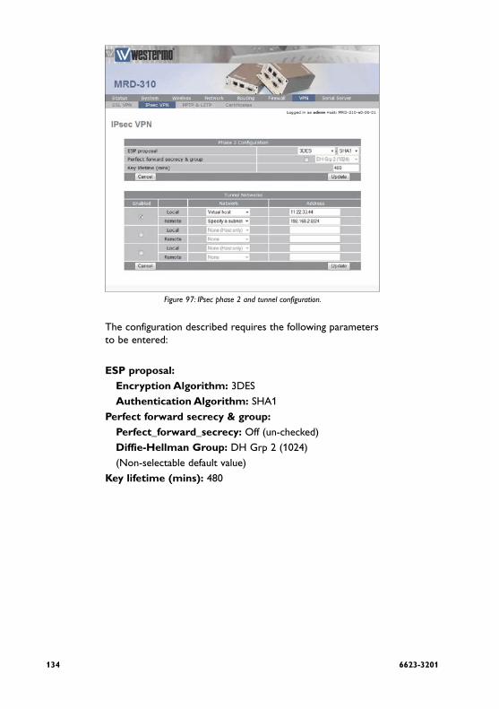
134 6623-3201
Figure 97: IPsec phase 2 and tunnel configuration.
The configuration described requires the following parameters to be entered:
ESP proposal:
Encryption Algorithm: 3DES
Authentication Algorithm: SHA1
Perfect forward secrecy & group:
Perfect_forward_secrecy: Off (un-checked)
Diffie-Hellman Group: DH Grp 2 (1024)
(Non-selectable default value)
Key lifetime (mins): 480

1356623-3201
Tunnel Network SettingsThe local tunnel will be configured as a virtual host with the IP address 11.22.33.44 and the remote connection will be to the LAN 192.168.2.0/24. For this configuration the following parameters are entered:
Enabled: Checked
Local:
Network: Virtual Host
Address: 11.22.33.44
Remote:
Network: Specify a subnet
Address: 192.168.2.0/24
To complete the process of adding the tunnel click the Update button. The tunnel will be saved and the General IPsec Configuration page will again be displayed, now with the new tunnel added to the Tunnels table, a shown in Figure 98.
Figure 98: IPsec based VPN main page with new tunnel listed in Tunnels table.

136 6623-3201
Enable IPsecTo complete the configuration in the General IPsec Configuration enable IPsec by checking the enabled check-box, and as the tunnel will traverse a NAT enable NAT traversal. Click Update to save the settings.
Figure 99: IPsec based VPN main page, with IPsec enabled.
IPsec StatusOnce the settings have been save IPsec will start and attempt to establish a tunnel with the remote host, note this may take several minutes to complete. To check the status of the tunnel click Status on the main menu then VPN on the sub-menu, a page similar to that shown in Figure 100 will be displayed. If the Status of the tunnel is Connected then the tunnel has been established and data can be passed over it.
To obtain further details on the VPN connection click the link
Detailed IPsec status, a page similar to that shown in Figure 101 will be displayed. This information is usually only required if the link is not behaving as expected or if the tunnel is not able to be established.
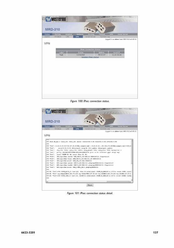
1376623-3201
Figure 100: IPsec connection status.
Figure 101: IPsec connection status detail.

138 6623-3201
6.3 PPTP and L2TP
6.3.1 Point-to-Point-Tunneling-Protocol
The Point-to-Point-Tunneling-Protocol (PPTP) is used for establishing Virtual Private Network (VPN) tunnels over an insecure network such as the Internet. PPTP uses a client server module for establishing the VPN, the MRD-3xx pro-vides a PPTP client. PPTP was developed by Microsoft and is provided with most versions of the Windows operating sys-tem. An advantage of PPTP is it is easy to configure.

1396623-3201
6.3.2 Layer 2 Tunnel Protocol
The Layer 2 Tunnel Protocol (L2TP) is an Internet Engineering Task Force (IETF) standard which combines the best features of two existing tunneling protocols, Layer 2 Forwarding (L2F) developed by Cisco and the Point-to-Point Tunneling Protocol (PPTP). L2TP can be viewed as an extension to the Point-to-Point Protocol (PPP). One endpoint of an L2TP tunnel is called the L2TP Network Server (LNS), the LNS waits for new tunnels to be established. The other endpoint is called the L2TP Access Concentrator (LAC), the LAC initiates tunnel connections to the LNS, the MRD-3xx implements an L2TP LAC. Once the L2TP tunnel has been established the traffic over the tunnel is bidirectional.

140 6623-3201
6.3.3 PPTP and L2TP Configuration
To access the PPTP & L2TP configuration page click VPN on the main menu then PPTP & L2TP on the sub-menu. The PPTP & L2TP page will list the currently configured tunnels, Figure 102 shows the page with no tunnels configured.
Figure 102: The PPTP & L2TP main page.

1416623-3201
6.3.4 Add a PPTP or L2TP Tunnel
To add a new PPTP or L2TP tunnel click the Add new tunnel button, the Add new tunnel page will be displayed as shown in Figure 103.
Figure 103: The PPTP & L2TP Add new tunnel page.
Add new tunnel options
Label A label or name for the tunnel.
Enabled Check the box to enable the tunnel.
Type Select the type of tunnel from the drop-down list, the options are:
PPTP Point-to-Point Tunneling Protocol
l2TP
Layer 2 Tunneling Protocol
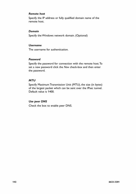
142 6623-3201
Remote host Specify the IP address or fully qualified domain name of the remote host.
Domain Specify the Windows network domain. (Optional)
UsernameThe username for authentication.
Password Specify the password for connection with the remote host. To set a new password click the New check-box and then enter the password.
MTU Specify Maximum Transmission Unit (MTU), the size (in bytes) of the largest packet which can be sent over the IPsec tunnel. Default value is 1400.
Use peer DNS Check the box to enable peer DNS.

1436623-3201
6.3.5 PPTP Configuration Example
The following is an example of connecting a PPTP tunnel to a PPTP VPN server, Figure 104 illustrates the network which will be established. For this example a connection will be established from the MRD-3xx to an PPTP server. The tunnel will be called test, it is of type PPTP and the remote host is at IP address 123.123.123.123. The domain is x, the username is qwerty and the password password. The MTU setting is left at the default of 1400 and peer DNS is enabled.
PPTP VPNtunnel
PPTP Server
Figure 104: SSL based VPN example network.

144 6623-3201
To access the PPTP & L2TP configuration page click VPN on the main menu then PPTP & L2TP on the sub-menu. The PPTP & L2TP page will then be displayed, to add a tunnel click the Add new tunnel button on the main PPTP & L2TP page, the Add new tunnel page will be displayed. Figure 105 illustrates the PPTP add tunnel page with the parameters entered for the configuration described above.
Figure 105: The PPTP & L2TP main page.
1456623-3201
The following settings are used to configured the tunnel as described:
Label: Test
Enabled: On (Checked)
Type: PPTP
Remote host: 123.123.123.123
Domain: x
Username: qwerty
Password: password
MTU: 1400
Use peer DNS: On (Checked)
Once the options have been entered click the Update button to add the tunnel.
The settings will be saved and the main PPTP & L2TP page will be displayed with the new tunnel added to the Tunnels table, as shown in Figure 106. The MRD-3xx will now attempt to establish a connection with the PPTP server.
Figure 106: The PPTP & L2TP main page.

146 6623-3201
To check the status of the page click Status on the main menu and then VPN on the sub-menu, the VPN status page will then be displayed. Figure 107 is the status page for the PPTP VPN created in this example.
Figure 107: The PPTP & L2TP main page.
The status of the tunnel is connected, indicating that the tun-nel has been established and traffic can flow. The status page also indicates the local IP address of the tunnels and the number of bytes that have been received and transmitted.
1476623-3201
6.4 Multiple VPN Tunnels
The MRD-3xx allows multiple VPN tunnels to operate simul-taneously. One SSL VPN, up to 3 IPsec tunnels and up to 3 PPTP/L2TP tunnels can be configure to operate simultane-ously. Figure 108 is an example of the VPN Status page with one SSL, one IPsec and one PPTP VPN tunnel operating.
Figure 108: The VPN status page showing 3 active VPN connections
148 6623-3201
6.5 Certificate Management
Digital certificates are a form of digital identification used for authentication. A digital certificate contains information that identifies a device or user, they is issued in the context of a Public Key Infrastructure (PKI), which uses public-key/private-key encryption to ensure security. The MRD-3xx unit supports X.509 digital certificates (International Telecommunications Union Recommendation X.509), including SSL (Secure Sockets Layer) certificates.
To access the certificate management page select VPN from the main menu and Certificates from the sub-menu, the page shown in Figure 109 will be displayed. The top part of the page lists the currently loaded certificates and second section is for uploading a new certificate to the MRD-3xx.
Figure 109: VPN Certificate management.

1496623-3201
6.5.1 Add a Certificate
To add a certificate click the Browse button, then navigate to the certificate and select it. In the example shown in Figure 110, the file demoClient.p12 is selected this contains the certifi-cate demoClient.
Figure 110: Uploading a VPN Certificate.

150 6623-3201
To upload the certificate to the MRD-3xx click the Upload to MRD-3xx button the page will be updated and the certificate will be added to the Certificates table as shown in Figure 111.
Figure 111: VPN Certificate table listing the uploaded certificate.

1516623-3201
6.5.2 Checking the Certificate Details
Once uploaded the details of a certificate can be displayed by clicking view located in the detail column of the table, Figure 112 is an example of the details of a certificate.
Figure 112: VPN Certificate details.

152 6623-3201
6.5.3 Adding Further Certificates
Additional certificates can be uploaded to the MRD-3xx, the process is the same as adding the first certificate. For each additional certificate click the Browse button, navigate to the certificate then click the Upload to MRD-3xx button.
Figure 113: Adding a second VPN Certificate.

1536623-3201
An example of adding a second certificate is shown in Figure 113. In this example the file demoClient2.p12 is selected, this file contains the certificate demoClient2, Figure 114 shows the certificate table with the second certificate added.
Figure 114: VPN Certificate table listing both uploaded certificates.

154 6623-3201
6.5.4 Deleting a Certificate
A certificate can be deleted by clicking the bin icon in the Delete column of the certificate to be deleted. When the icon is clicked a warning box will be displayed. Click OK to confirm the deletion or Cancel to prevent the certificate from being deleted.
For example to delete certificate 2 from the table shown in Figure 114, click the bin icon in row 2 of the table. A warning box will now be displayed as shown if Figure 115, click OK.
Figure: 115 Deleting a VPN Certificate.
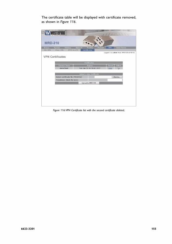
1556623-3201
The certificate table will be displayed with certificate removed, as shown in Figure 116.
Figure 116: VPN Certificate list with the second certificate deleted.

156 6623-3201
7 Serial Server
The serial server is used to transfer data between a physical serial port and an IP connection. The IP connection can be via the Ethernet or the wireless connection of the unit. The remote host that connects to the serial server could be a SCADA master, desktop PC or even another unit.
7.1 Selecting a port function
Each port of the serial server can be configured to operate with a different function. The function selected for an applica-tion will be determined by the serial equipment attached to the port and the type of IP connection required. The unit offers the following functions:
Disabled Serial server functionality is disabled for the port.
Raw TCP Client/ServerThe serial server function create a transparent pipe between the serial port and a TCP network connection. Example uses of this mode include connecting to a remote PC running serial port redirector software with virtual COM ports or connect-ing two units back-to-back to create a serial bridge.
Raw UDPThis function is similar to Raw TCP Client/Server mode, but uses UDP as the network transport. UDP has lower over-heads than TCP, but as UDP offers no lost packet detection, this function should only be used with serial protocols than can provide the necessary error correction.
Unit EmulatorThe serial server provides an AT command interface at the serial port that simulates a traditional dial-up unit. However, instead of dialing out phone calls, the emulator creates TCP network connections. The emulator will also simulate incom-ing calls if it receives a TCP connection. The function is suited to applications where equipment attached to the serial port expects to see a dial-up unit.

1576623-3201
DNP3 IP-Serial Gateway The serial server will act as a DNP3 outstation to be polled by a SCADA master. The outstation mode is configurable as a TCP listen endpoint, TCP dual-function endpoint or UDP endpoint.
Modbus IP-Serial Gateway The serial server will perform conversion from Modbus/TCP to Modbus/RTU or Modbus/ASCII, allowing polling by a Modbus/TCP master.
Telnet (RFC 2217) ServerThe serial server will function as a Telnet server, including the protocol extensions defined in RFC 2217. In addition to trans-porting data, this mode also allows a remote PC with appro-priate software to change the port configuration (baud rate etc) and read and write the handshaking lines during a session.

158 6623-3201
7.2 Common configuration options
7.2.1 Serial port settings
Regardless of the selected port function, each port needs to be configured to match the parameters of the equipment attached to the port. As the configuration of a port function is edited, the options displayed in Figure 117 will be shown.
Figure 117: Common port configuration parameters
For each port, the following parameters can be set:
Baudrate The port can be configured for any standard baudrate from 300 baud to 230400 baud.
Databits The port can be configured for operation with 5 to 8 databits.
StopbitsThe port can be configured for operation with 1 or 2 stopbits.
ParityThe port can be configured for none, odd or even parity.
Flow controlThe serial server port can be configured for the following modes:

1596623-3201
NoneNo flow control is enabled.
Hardware The port will use the RTS and CTS handshake lines to control the flow of data.
Software The port will use XON/XOFF software flow control. The XOFF character is hex 0x11. The XON character is hex 0x13.
BothThe port will use both hardware and software flow control.
Line state when disconnected This field determines the state of the port's RTS and DTR handshaking lines while the port is disconnected. To set a sig-nal active while disconnected, check the associated box.
Most equipment uses 8 databits, 1 stopbit and no parity, how-ever, this should be verified against the reference manual for the equipment.

160 6623-3201
7.2.2 Packet framer settings
The packet framer is available for all port functions that carry raw data (these settings are not available for the DNP3 IP-Serial Gateway or Modbus IP-Serial Gateway). The packet framer allows data received from the serial port to be pack-etised into larger blocks, reducing the overhead incurred when repeated packets of small sizes are sent over the network.
Figure 118: Packet framing configuration options
The following options control the packet framer:
Maximum packet size This value determines the largest packet size to be passed to the network for transmission. If set to 0, the packet framer will be disabled and data will bypass the packet framer. The value chosen will depend on the application, however, the value should not be set higher than 1024, so the packet will fit a conventional Ethernet frame.
Minimum size before sending In some applications, it may not be desirable to wait for the exact number of bytes specified in Maximum packet size before sending the packet. The value set in this field, which must be less than or equal to the Maximum packet size, acts as a send threshold. Once the accumulated byte count reaches this value, the packet will be sent.

1616623-3201
Timeout before sendingThe timeout allows data accumulated by the framer to be sent after a specified period of serial receive inactivity. This pre-vents data from being held in the framer indefinitely should no more data arrive on the serial port. The timeout is set in 100 millisecond units, so, for example, a one second timeout would be set as a value of 10.
Immediate send character matching This field allows the framer to be configured so that if certain characters are received the accumulated data is immediately sent. The character matching can function in two modes:
Match any characterIf either of the characters set the in Match characters field are received, the data will be sent immediately.
Match all characters If both of the characters set in the Match characters field are received in order, the data will be sent immediately.
Match charactersUsed in conjunction with the Immediate send character matching field, these characters determine what data will cause an immediate send. The values are entered as a hex value, so, for example, a newline (ASCII 10) would be entered as 0A. To delete a value, clear the text in the field.
Characters to wait after matchUsed in conjunction with the Immediate send character matching field, this count determines how many additional characters will be received after an immediate match charac-ter is detected. This is useful if some trailing characters always follow the match character.

162 6623-3201
7.3 Raw TCP Client/Server
7.3.1 Description
The serial server will create a transparent pipe between the serial port and a TCP network connection. Example uses of this mode include connecting to a remote PC running serial port redirector software with virtual COM ports or connect-ing two units back-to-back to create a serial bridge.
7.3.2 Selecting the port function
The serial server configuration is accessed by selecting Serial Server from the main menu and Port Setup from the submenu. To enable a port for Raw TCP Client/Server function, select Raw TCP Client/Server from the Function column of the appro-priate port. Once selected, click Update to confirm the change. Once confirmed, the port will display as shown in Figure 119.
Figure 119: Selecting Raw TCP Client/Server function

1636623-3201
7.3.3 Configuring the port function
Once the port function has been selected, click the pencil icon in the Edit column to change the configuration of the port.
Figure 120: Raw TCP Client/Server configuration

164 6623-3201
As shown in Figure 120, the following options can be set for the Raw TCP Client/Server:
Network type The Raw TCP serial server can be configured for three differ-ent network modes:
Accept The serial server will listen for TCP connections on the specified port number.
Connect The serial server will establish a TCP connection to the specified address and port number.
Accept and Connect The serial server will normally listen for TCP connec-tions on the specified port number, however, if data is received at the serial port and no connection exists, it will attempt to establish a connection to the specified address and port number.
Connect address For Connect or Accept and Connect network modes, this is the address the server will attempt to connect to. The address entered should be in IPv4 decimal dotted notation.
Connect port For Connect or Accept and Connect network modes, this is the TCP port number the server will attempt to connect to. The value entered should be a valid TCP port number.
Timeout after failed connect For Connect or Accept and Connect network modes, if a con-nection request has failed, the server will wait the amount of time (in seconds) specified in this field before attempting another connection request. While a short timeout may cause the connection to be established more quickly, it may also cause greater network traffic if the remote host is unavailable and repeated attempts fail.

1656623-3201
Failed connects before giving up For Accept and Connect network modes, the serial server will attempt to establish a connection for the number of times specified in this field before giving up and waiting for a con-nection to be accepted.
Accept portFor Accept or Accept and Connect network modes, this is the TCP port number that the server will listen for connections on.
Drop current if new accept For Accept or Accept and Connect network modes, if a TCP connection is currently active on the serial server, and a new connection request is accepted, this field determines the action that will be taken. If set, the new connection will become the active connection and the existing connection will be closed. If not set, the existing connection will remain active and the newly received connection will be closed.
TCP keepalive time When set to a value greater than 0, TCP keepalives will be enabled for connections, with probes sent at the frequency specified (minutes). This may assist in detecting failed connec-tions.
For information on setting the Port Configuration, see section 7.2.1. For information on setting the Packet Framing, see sec-tion 7.2.2.

166 6623-3201
7.4 Raw UDP
7.4.1 Description
This function is similar to Raw TCP Client/Server mode, but uses UDP as the network transport. UDP has lower over-heads than TCP, but as UDP offers no lost packet detection, this function should only be used with serial protocols than can provide the necessary error correction.
7.4.2 Selecting the port function
The serial server configuration is accessed by selecting Serial Server from the main menu and Port Setup from the submenu. To enable a port for Raw UDP function, select Raw UDP from the Function column of the appropriate port. Once selected, click Update to confirm the change. Once confirmed, the port will display as shown in Figure 121.
Figure 121: Selecting Raw UDP function

1676623-3201
7.4.3 Configuring the port function
Once the port function has been selected, click the pencil icon in the Edit column to change the configuration of the port.
Figure 122: Raw UDP configuration

168 6623-3201
As shown in Figure: 122, the following options can be set for Raw UDP mode:
Send address This is the address the serial server will send UDP packets to. The address entered should be in IPv4 decimal dotted nota-tion.
Send port This is the UDP port number the server will send UDP pack-ets to. The value entered should be a valid UDP port number.
Local receive port This is the UDP port number that UDP packets will be received on at the unit. The value entered should be a valid UDP port number.
For information on setting the Port Configuration, see section 7.2.1. For information on setting the Packet Framing, see sec-tion 7.2.2.

1696623-3201
7.5 Unit Emulator
7.5.1 Description
The serial server provides an AT command interface at the serial port that simulates a traditional dial-up unit. However, instead of dialing out phone calls, the emulator creates TCP network connections. The emulator will also simulate incom-ing calls if it receives a TCP connection. The function is suited to applications where equipment attached to the serial port expects to see a dial-up unit.
7.5.2 Selecting the port function
The serial server configuration is accessed by selecting Serial Server from the main menu and Port Setup from the submenu. To enable a port for the Unit Emulator function, select Unit Emulator from the Function column of the appropriate port. Once selected, click Update to confirm the change. Once con-firmed, the port will display as shown in Figure 123.
Figure 123: Selecting Unit Emulator function

170 6623-3201
7.5.3 Configuring the port function
Once the port function has been selected, click the pencil icon in the Edit column to change the configuration of the port.
Figure 124:Unit Emulator configuration

1716623-3201
As shown in Figure 124, the following options can be set for the Unit Emulator:
Dial out destination address This field determines how the emulator will handle dial requests from the serial port (ATDxxxx commands). The dial address may be set by:
Fixed destination Regardless of the value entered after the ATD command, the emulator will always connect to the host specified in the Fixed destination address and Fixed destination port fields.
From dial stringThe emulator will parse the ATD command to extract the destination address and port number. The examples below show the two different formats that can be used to create a connection to the address 192.168.2.200 and port number 6001.
Dotted Dial string is ATD 192.168.2.220:6001
Padded Dial string is ATD 0109020106080202020006001
From phone book When a dial command is entered, the emulator will look up the unit's phone book and attempt to translate the number to an address and port number. More details on the phone book can be found in section 7.9.
Accept incoming calls When set, the emulator will listen for TCP connections on the port number specified in the Accept port field. When a con-nection is received, the emulator will indicate a ring condition at the serial port. The equipment can then answer the call or wait for the emulator to automatically answer. Once answered, the emulator will indicate that the connection is open and data will pass between the remote host and the serial port.

172 6623-3201
Accept port This is the TCP port number that the server will listen for connections on.
On-answer signaling When set, the emulator will behave as follows: When accept-ing an incoming connection, the emulator will transmit a single byte to the remote host when the call is answered. When establishing an outgoing connection, the emulator will wait for the first byte of data before signaling that the call has con-nected at the serial port.
TCP keepalive time When set to a value greater than 0, TCP keepalives will be enabled for connections, with probes sent at the frequency specified (minutes). This may assist in detecting failed connec-tions.
Rings until answered This field determines the default number of rings the emulator will wait before automatically answering a call. This is equiva-lent to setting the ATS0 S-Register in a conventional unit.
DCD mode This field determines the default state of the Data Carrier Detect (DCD) handshaking line. The following modes are sup-ported:
Always on Regardless of the online state of the emulator, the DCD line will be active (equivalent to AT&C0).
Follow carrier The DCD line will be active when the emulator is in the online state (equivalent to AT&C1).

1736623-3201
DTR function This field determines the default response of the unit to changes in the Data Terminal Ready (DTR) handshaking line. The following modes are supported:
Ignore The emulator will ignore changes to the state of DTR (equiva-lent to AT&D0).
Command mode If the DTR line transitions from the active to inactive state while the emulator is on online data mode, the emulator will drop to AT command mode (equivalent to AT&D1).
Hangup If the DTR line transitions from the active to inactive state while the emulator is on online data mode, the emulator will terminate the current call (equivalent to AT&D2).
For information on setting the Port Configuration, see section 7.2.1. For information on setting the Packet Framing, see sec-tion 7.2.2.

174 6623-3201
7.6 DNP3 IP-Serial Gateway
7.6.1 Description
The DNP3 IP-Serial Gateway carries out translation between DNP3 Serial and DNP3 TCP protocols. This has several advan-tages:
DNP3 frames are not fragmented. The translation soft-• ware identifies and transmits DNP3 link layer frames without fragmentation, ensuring reliable transport of the DNP3 data in a single TCP or UDP packet.
Sever serial port emulation is not required. The SCADA • server can communicate with the DNP3 device directly via TCP rather than through serial port emulation soft-ware. This reduces the complexity and number of soft-ware layers required on the SCADA servers.
Dual function endpoint. The remote station can return • unsolicited messages, DNP3 serial data to the SCADA server.

1756623-3201
7.6.2 Selecting the port function
The serial server configuration is accessed by selecting Serial Server from the main menu and Port Setup from the submenu. To enable a port for the DNP3 IP-Serial Gateway function, select DNP3 IP-Serial Gateway from the Function column of the appropriate port. Once selected, click Update to confirm the change. Once confirmed, the port will display as shown in Figure 125.
Figure:125: Selecting DNP3 Gateway function

176 6623-3201
7.6.3 Configuring the port function
Once the port function has been selected, click the pencil icon in the Edit column to change the configuration of the port.
Figure 126: DNP3 Gateway configuration

1776623-3201
As shown in Figure 126 the following options can be set for the DNP3 Serial-IP Gateway:
Station typeThe DNP3 IP-Serial Gateway can be configured to operate in three modes:
TCP listen endpoint The serial server will listen for TCP connections on the speci-fied port number.
TCP dual endpoint The serial server will normally listen for TCP connections on the specified port number, however, if a valid DNP packet is received at the serial port and no connection exists, a connec-tion will be established to the specified master address. This is useful if a SCADA master will poll periodically but facility is required to support unsolicited responses.
UDP endpoint The serial server will operate in UDP mode, receiving data on the specified port number and transmitting responses to the specified master.
Listen port For all station types, this determines the TCP/UDP port the serial server will listen for connections (TCP) or data (UDP) on. The value entered should be a valid TCP/UDP port number. The default DNP3 port number is 20000.
Master address This is the IP address of the SCADA master. The address entered should be in IPv4 decimal dotted notation.
Master port This is the TCP/UDP port the serial server will connect to (TCP) or transmit to (UDP). The value entered should be a valid TCP/UDP port number. The default DNP3 port number is 20000.

178 6623-3201
Only accept data from master IP address When set, this field will cause the serial server to only accept data sourced from the address set in the Master address field.
Timeout for TCP connections For TCP connections only, when this field is set to a value greater than 0, the serial server will close connections that have had no receive activity for longer than specified (sec-onds).
Drop existing TCP connection if new received For TCP connections only, if a connection is currently active on the serial server, and a new connection request is accepted, this field determines the action that will be taken. If set, the new connection will become the active connection and the existing connection will be closed. If not set, the existing con-nection will remain active and the newly received connection will be closed.
Timeout between failed TCP connects For TCP dual endpoint only, if a connection request has failed, the server will wait the amount of time (in seconds) specified in this field before attempting another connection request. While a short timeout may cause the connection to be estab-lished more quickly, it may also cause greater network traffic if the remote host is unavailable and repeated attempts fail.
Failed TCP connects before giving up For TCP dual endpoint only, the serial server will attempt to establish a connection for the number of times specified in this field be giving up and waiting for a connection to be accepted.
Destination address for UDP packets For UDP endpoint only, the serial server can be configured to behave as follows:

1796623-3201
Master address and port Packets transmitted over network will always be sent to the address specified in the Master address and Master port fields.
Address and port of last request Packets transmitted over network will be sent to the source address of the most recently received packet. If no packets have been received, packets will be transmitted to the address specified in the Master address and Master port fields.
For information on setting the Port Configuration, see section 7.2.1.

180 6623-3201
7.7 Modbus IP-Serial Gateway
7.7.1 Description
The Modbus IP-Serial Gateway carries out translation between Modbus/TCP and Modbus/RTU or Modbus/ASCII. This means that Modbus serial slaves can be directly attached to the unit's serial ports without any external protocol convertors.
7.7.2 Selecting the port function
The serial server configuration is accessed by selecting Serial Server from the main menu and Port Setup from the submenu. To enable a port for the Modbus IP-Serial Gateway function, select Modbus IP-Serial Gateway from the Function column of the appropriate port. Once selected, click Update to confirm the change. Once confirmed, the port will display as shown in Figure 127.
Figure 127: Selecting Modbus Gateway function

1816623-3201
7.7.3 Configuring the port function
Once the port function has been selected, click the pencil icon in the Edit column to change the configuration of the port.
Figure 128: Modbus Gateway configuration
As shown in Figure 128, the following options can be set for the Modbus Gateway:
TCP accept port This field determines the TCP port number that the serial server will listen for connections on. The value entered should be a valid TCP port number. The default Modbus/TCP port number is 502.
Drop current if new accept If a connection is currently active on the serial server, and a new connection request is accepted, this field determines the action that will be taken. If set, the new connection will become the active connection and the existing connection will be closed. If not set, the existing connection will remain active and the newly received connection will be closed.
182 6623-3201
Connection timeout When this field is set to a value greater than 0, the serial serv-er will close connections that have had no network receive activity for longer than the specified period
Transmission mode Select RTU or ASCII, based on the Modbus slave equipment attached to the port.
Response timeout This is the timeout (in milliseconds) to wait for a response from a serial slave device before retrying the request or returning an error to the Modbus master.
RTU framing timeout This is the timeout (in milliseconds) the the serial server will use to determine the boundaries of Modbus/RTU packets received on the serial port.
Retries Should no valid response be recieved from a Modbus slave, the value in this field determines the number of times the serial server will retransmit requests before giving up.
For information on setting the Port Configuration, see section 7.2.1.
1836623-3201
7.8 Telnet (RFC 2217) Server
7.8.1 Description
Telnet server mode is ideal for connecting serial terminal equipment, as a standard Telnet client can be used to connect to the server.
The Telnet sever mode also supports the RFC 2217 exten-sions, which, when used with a remote PC running appropri-ate serial port redirector software, allow port configuration changes (such as the baudrate) to be transmitted over the network to the unit. Changes in unit handshaking lines are also transmitted.

184 6623-3201
7.8.2 Selecting the port function
The serial server configuration is accessed by selecting Serial Server from the main menu and Port Setup from the submenu. To enable a port for the Telnet Server function, select Telnet (RFC 2217) Server from the Function column of the appropri-ate port. Once selected, click Update to confirm the change. Once confirmed, the port will display as shown in Figure 129.
Figure 129: Selecting Telnet Server function

1856623-3201
7.8.3 Configuring the port function
Once the port function has been selected, click the pencil icon in the Edit colum to change the configuration of the port.
Figure 130: Telnet Server configuration

186 6623-3201
As shown in Figure 130, the following options can be set for the Telnet Server:
Accept port This field determines the TCP port number that the serial server will listen for connections on. The value entered should be a valid TCP port number.
Drop current if new accept If a connection is currently active on the serial server, and a new connection request is accepted, this field determines the action that will be taken. If set, the new connection will become the active connection and the existing connection will be closed. If not set, the existing connection will remain active and the newly received connection will be closed.
TCP keepalive time When set to a value greater than 0, TCP keepalives will be enabled for connections, with probes sent at the frequency specified (minutes). This may assist in detecting failed connec-tions.
For information on setting the Port Configuration, see section 7.2.1. For information on setting the Packet Framing, see sec-tion 7.2.2.

1876623-3201
7.9 Phone Book
7.9.1 Description
The Phone Book works in conjunction with the Unit Emulator to provide a translation table from traditional phone num-bers to IP addresses and port numbers. This allows the Unit Emulator to be used as a drop in replacement for a traditional dial-up unit and to create IP connections rather than phone calls.
For more information on the Unit Emulator, see section 7.5.
To access the Phone Book configuration, select Serial Server from the main menu and Phone Book from the submenu. The page will initially have no entries, as shown in Figure 131.
Figure 131: Phone Book with no entries configured

188 6623-3201
7.9.2 Phone Book Options
To access the phone book options click the Add new phone book entry button on the main Phone Boook page. Figure 132 shows the page for entering a new entry.
Figure 132: Page for adding Phone Book entry
The following options can be set for each entry:
Dial string This is the phone number that the dial command will attempt to match against.
Connect address This is the IP address the serial server will attempt to con-nect to.
Connect port This is the IP port number the serial server will attempt to connect to.

1896623-3201
7.9.3 Adding a new phone book entry
From the main phone book page click the Add new phone book entry button. An example of adding a new entry is shown in Figure 133. In this example a new entry is cre-ated that translates dial string 123 to connection address 123.123.123.123:123.
Figure 133: Adding a Phone Book Entry

190 6623-3201
Click Update to save the new entry. The phone book table will be updated to include the new entry as shown in Figure 134.
Figure 134: The Phone Book page with a single entry
To add a second entry click the Add new phone book entry button. In the example shown in Figure 135, an entry is cre-ated which translates dial string 234 to connection address 234.234.234.234:234.
Figure 135: Adding a second entry

1916623-3201
To commit the new phone book entry to the table, click the Update button. The main page will again be shown with the new entry added, as seen in Figure 136.
Figure 136: The phone book page with two phone book entires

192 6623-3201
7.9.4 Editing a phone book entry
A phone book entry can be editied by clicking the pencil icon in the Edit column of the entry to be changed. Once clicked, the details of the entry will be displayed in the same table as when creating a new phone book entry.
As an example, to edit the second phone book entry in the table, click the pencil icon in the second row of the table. To change the connect port of the entry to 235, changes were made as shown in Figure 137.
Figure 137: Editing a phone book entry
To save the changes click the Update button or to lose any changes click the Cancel button. The main page will again be displayed as shown in Figure 138, with the changes for entry 2 added to the table.

1936623-3201
Figure 138: Main phone book page with revised entry
7.9.5 Deleting a phone book entry
A phone book entry can be deleted by clicking the bin icon in the Delete column of the entry to be deleted. A warning box will be displayed. Click OK to confirm the deletion.
For example, to delete phone book entry 2 from the table shown in Figure 138, click the bin icon in row 2 of the table. A warning box will now be displayed as shown if Figure 139. Click OK.

194 6623-3201
Figure 139: Deleting a phone book entry
The phone book table will be displyed with the entry removed, as shown in Figure 140.
Figure 140: Phone boook table after deletion of entry

1956623-3201
8. AT Command Set
This section lists the AT Commands support by the MRD-3x0 Modem/Router. The commands are accessed via the serial port when the unit is in either Circuit Switched Data (CSD) mode or the serial port is set to modem emulation mode.
Basic Command Set
Command Description Usage
A Answer incoming call To answer incoming call: ATA
D Dial a phone number To dial phone number 12345678: ATD12345678
E Local echo ATE0 – No echo ATE1 - Echo
H Hangup current call ATH or ATH0 - Hangup current call
I Query modem iden-tification
ATI
L Speaker volume Accepted but ignored
M Monitor mode Accepted but ignored
O Return to online mode
While the modem is in the online state but command mode, to return to data mode: ATO
P Pulse dialing Accepted but ignored
Q Set quiet responses ATQ0 – No quiet responses
ATQ1 – Quiet responses
T Tone dialing Accepted but ignored
V Set verbose respons-es
ATV0 – No verbose responses
ATV1 – Verbose responses
X Set connect result format
Accepted but ignored
Z Initialise the modem ATZ

196 6623-3201
Extended Command Set
Command Description Usage
&C Data Carrier Detect (DCD) mode
AT&C0 – DCD always on
AT&C1 – DCD on while in online mode
&D Data Terminal Ready (DTR) function
AT&D0 – Modem ignores DTR.
AT&D1 – DTR ON - >DTR OFF while in online mode causes modem to drop to command mode
AT&D2 – DTR ON -> DTR OFF while in online mode causes modem to hangup
&F Initialise the modem ATF
&S Data Set Ready (DSR) mode
AT&S0 – DSR always on
AT&S1 – DSR on while negotiating or connected.

1976623-3201
Configuration Registers
Register Description Usage
S0 Rings until incoming call is automatically answered
No auto answer: ATS0=0
Answer after two rings: ATS0=2
S1 Ring counter To view the number of times to line has rung in this call: ATS1?
S2 Set ESC character (default '+')
Determines the character used to drop from data mode to command mode.
When in online data mode, the sequence:
<S12 time idle>
<ESC><ESC><ESC>
<S12 time idle>
will cause the modem to drop to command mode
S3 Set CR (carriage return) character
S4 Set LF (linefeed) character
S5 Set BS (backspace) character
S7 Timeout for con-nection completion (seconds)
S12 Escape sequence guard time (1/50's of a second)
See S2

198 6623-3201
Wireless Network-Specific Commands
Command Description Usage
+CREG Query the current network registration state
AT+CREG=? If registered will return:
+CREG: 0,1 If not registered will return:
+CREG: 0,2
+CSQ Query the current signal strength level
To query current level: AT+CSQ
To query possible values: AT+CSQ=?
+CMGL List received SMSs If an SMS message is received and accepted by the modem, and the message does not match any internal SMS triggers, the message will be queued.
To list unread queued messages: AT+CMGL=”REC UNREAD”
To list read queued messages: AT+CMGL=”REC READ”
To list all messages: AT+CMGL=”ALL”
+CMGR Read a specific received SMS
To read message with index 1: AT+CMGR=1
+CMGD Delete an SMS The delete message with index 2: AT+CMGD=2
+CMGS Send an SMS To send an SMS to 12345678: AT+CMGS=”12345678”
Modem will respond with: > Text can now be entered. To end the message, send Ctrl-Z.

RE
V.b
662
3-32
01 2008-10 M
älartryck AB, Eskilstuna, Sweden
Westermo Teleindustri AB • SE-640 40 Stora Sundby, SwedenPhone +46 16 42 80 00 Fax +46 16 42 80 01
E-mail: [email protected] Westermo Web site: www.westermo.com
Westermo Teleindustri AB have distributors in several countries, contact us for further information.
Westermo Data Communications AB SE-724 81 Västerås Phone: +46 (0)16 42 80 00 • Fax: +46 (0)21 35 18 50 [email protected]
Westermo Data Communications Ltd Talisman Business Centre • Duncan Road Park Gate, Southampton • SO31 7GA Phone: +44(0)1489 580-585 • Fax.:+44(0)1489 580586 E-Mail: [email protected]
Westermo Data Communications GmbH Goethestraße 67, 68753 Waghäusel Tel.: +49(0)7254-95400-0 • Fax.:+49(0)7254-95400-9 E-Mail: [email protected]
Westermo Data Communications S.A.R.L. 9 Chemin de Chilly 91160 CHAMPLAN Tél : +33 1 69 10 21 00 • Fax : +33 1 69 10 21 01 E-mail : [email protected]
Westermo Data Communications Pte Ltd 2 Soon Wing Road #08-05 Soon Wing Industrial Building Singapore 347893 Phone +65 6743 9801 • Fax +65 6745 0670 E-mail: [email protected]
Subsidiaries