web controllable devices, concept and design
TRANSCRIPT

ICS-EB 724
Technische Universiteitt(i)Eindhoven
Faculty of Electrical EngineeringSection of Information and Communication Systems (ICS/EB)
Master's Thesis
WEB CONTROLLABLE DEVICES,CONCEPT AND DESIGN.
ing H.A.Aalderink
Coach:Coach:Supervisor:Date:
dr.ir.A.C.Verschuerening A.H.J.G. Lommen (TNO Institute of Industrial Technology)prof.ir.M.P.J.StevensAugust 1999
The Faculty of Electrical Engineering of the Eindhoven University of Technology does notaccept any responsibility regarding the contents of Master's Theses

Web controllable devices, concept and design.
Abstract
This master's thesis is written as part of the M.Sc. course in information technology at thedepartment of electronic engineering of the Eindhoven University of technology. All work in thisthesis is the result of a joined project with TNO (Netherlands Organisation f,or Applied ScientificResearch) Institute of Industrial Technology.
This thesis explores the concept of web controllable devices with respect to:
• Choice of protocol stack and location of functionality: Telnet TCP and IPv6 on the device andHTTP on the server which contains the web pages and CGI-script too.
• Choice of a pipelined data processor implementation of the protocol stack on the device.• Discussion about Internet delay and the proposal of safety envelopes• Discussion of modelling the Internet delay in controlled systems.
The design of the chosen pipelined data processor discusses:
• Testability of the designed protocol processor.• The processing architecture• A general interface to data-communication circuits• A bus structure to process the extension headers in the order in which they appear in the
IPv6 Payload package.• An unit for insertion of payload length to solve the causality problem in pipelined encoders
for variable length messages
The designed units are modelled in synthesisable VHDL to generate design feedback andfunctional prototypes using a rapid prototyping board populated with FPGA's developed withinTNO.
Page 1

Web controllable devices, concept and design.
1 Contents
1 CONTENTS 2
2 INTRODUCTION 3
3 WEB CONTROLLABLE DEVICES 4
3.1 THE PROTOCOL STACK OF WEB CONTROLLABLE DEVICES ................................................................•...........•..... 5
3.2 HARD- OR SOFTWARE STACK IMPLEMENTATION 83.3 CONTROLLABILITY OF WEB CONTROLLED DEVICES 83.4 INTERNET DELAY IN A WEB CONTROLLED SYSTEM IN A STEERING CONFIGURATION 9
3.5 CONTROL IN A REGULATING CONFIGURATION 11
3.6 THE DEVELOPMENT PROCEDURE 13
4 DESIGN 14
4.1 THE NETWORK ABSTRACTION SUB-LAYER AND ITS INTERFACE 17
4.1.1 The needs ofthe 1P protocol-layer 174.1.2 Controlling a variety ofLAN's 174.1.3 A Network Abstraction Sub-layer for Serial Lines using SLIP 19
4.2 IPv6 ENCODER AND DECODER 20
4.2.1 The 1Pv6 protocol 204.2.2 IPv6 encoder 224.2.3 IPv6 Decoder 23
4.3 EXTENSION HEADERS AND THE X-BUS 24
4.3.1 Extension Header 244.3.2 The X-bus 25
4.4 LAST MINUTE LENGTH INSERTION 29
4.5 INTERNET CONTROL MESSAGE PROTOCOL. 30
4.5.1 ICMPv6 304.5.2 The ICMPv6 design 31
4.6 CONFIGURATION DATA 32
5 MODELS AND FUNCTIONAL PROTOTYPES 33
6 CONCLUSIONS AND FUTURE WORK 37
7 REFERENCES 38
Page 2

Web controllable devices, concept and design.
2 Introduction
The Internet is growing rapidly and almost every day new ways of using the Internet emerge.The Internet finds its solid base in the Internet standards. The specifications of the Internetstandards are publicly accessible via the Internet. The Internet Engineering Task Force (IETF)does the development of new Internet protocols. The IETF research is done in workgroups. Theworkgroup publishes its findings in Requests For Comment's (RFC's). These RFC's are notstandards, they are just proposals that could end up as internet standard. The latest version ofthe basic Internet Protocol (IPv6) is currently in this process and has some very desirableproperties (like longer address fields) but also some awkward ones (the composition of themessage header is no longer fixed, making it difficult to handle these messages in hardware).
The expansion of embedded systems is a less visual, due to its stealthy character. Almost allelectronic devices have smart user-interfaces and remote controls. The use of embeddedsystems has opened the possibility to design user-oriented interfaces rather than letting userinterfaces be dictated by the mechanical and electrical demands of a device's function.
The next logical step in the evolution of embedded devices is to connect the embedded systemto the Internet. More devices will have Internet connectivity. At first only industrial systems, but inthe end even household appliances will have an Internet connection. Imagine programming yourVCR at the other side of the globe with an organiser.
The development and concept of web controlled devices contains issues from different scientificfields: Controlled systems, queuing theory, computer science and telecommunication.
In this thesis, we will develop an IPv6 controller which can be integrated with the hardware of anembedded system to form a 'system on a chip' with internet connectivity.
Page 3

Web controllable devices, concept and design.
3 Web Controllable Devices
Embedded systems are used in a lot of electrical devices. They are used as controllers for allkinds of systems and as intermediates between a system and a user-interlace. So the userinterlace is not directly connected with the controlled system. This is depicted in figure 3.1
UserI~ ~
Embedded ControlledUser interface system system
Figure 3.1 Embedded system as mtermechate.
This means the user interlace could be placed at an other location, as in remote controls. Whena user-interlace and the embedded system are connected trough the Internet, the device couldbe controlled from every Internet equipped location. The user interlace could be integrated in aweb page, so the device would be web controlled.
This concept raises some questions:
• Which Internet protocols should be used to connect the web browser to the device?• Should the protocols in the device be developed in hardware or in software?• What are the security aspects?• Which kinds of control could be developed and what are their limitations?• What are the effects of the packet delay on the controllability?
These issues are discussed in paragraphs.
Page 4

Web controllable devices, concept and design.
3.1 The protocol stack of web controllable devices
The web provides a platform independent way to exchange information worldwide. When adevice is connected to the web, it would be possible to control it from any web browser on theglobe. It would be another level in remote control with enormous possibilities.
A web browser uses HTTP (HyperText Transfer Protocol) to communicate to a HTrp server.The browser requests the web page from this server. The server sends the requested HTML(Hyper-Text Mark-up Language) file to the browser. When the web page contains images orother objects the browser requests them separately when the HTML-'file is processed. Interactiveweb pages contain CGI (Common Gateway Interface) requests. When an HTTP server receivesthe CGI request it starts the requested program. The output of the program is redirected by theserver to the browser.
The web page of the web controlled device must be stored somewhere. When the page is storedwithin the web-controlled device, every device needs a storage facility for its own page. Thepage could also be stored on a server, generally this will be a local server. This opens thepossibility to create several web pages for one device. These pages can contain user tailoredinterfaces on a need-to-control (as in need-to-know) base. Bearing in mind a local server isgenerally present, user tailored interfaces and the costs of the storage medium, storing theinterface web page on the server is the best choice.
To access the web-controlled device the web browser uses HTTP to request the web page. TheHTTP server sends the web page to the browser. Since the page is on a server, it is obvious toplace the HTTP server functionality on that server. This makes that server a web server.Generally the local web server is chosen to perform this task.
Unfortunately there exists no Internet standard protocol to control a device directly from a webpage. So the device has to use another protocol to interface between the web browser and thedevice. The most obvious choice would be to use the TELNET protocol to control the device.This protocol can be used to create a textual command interface. So the device would not onlybe web-controllable, it will be net-controllable. Since the World Wide Web is one of the Internetapplications, the net controllable device would have more possibilities than the web controllabledevices. It could be controlled by a web browser or a telnet application and would be able tosend and receive e-mail. On top of that it could be controlled by another device.
Additional software is needed to generate the textual commands in response of the interactiveweb components (e.g. buttons, dialog boxes, etc). The interactive web components needhandlers. The handler function can be performed by an applet running on top of the browser or acgi-script or servlet running on a server. This generally would be the server that contains theweb page. These two possibilities are depicted in figure 3.2
Page 5

Web controllable devices, concept and design.
r------------...];--H_T_r_p-+
I i CGI
1..._.._ .Glient... .
::I:-Is:r-
r·································· ·..···········..··· :
I I..._T_e_ln_e_t--1l~ I
I Il_oeVice_J
::I:-Is:r-
1""" ············1"".
I4-_H_T_T_P-+~ ~
I ,
I I
L--C1ient.J
Telnet
r·················..··..··..···································..·1
I _oev;ce..__ ,Figure 3.2 Distributions of protocols for web controllable devices
Both options result in the same requirements for the device. The selection of an option is mainlya security-related subject. When the handler is situated on a server behind a firewall, the firewallcould block direct access to the device. This way the device can be protected againstunauthorised actions via the net. When the handler is located on the client, hostile hosts canimitate the client and access the device.
The choice for a separate HTTP server over an embedded one results in a net controllabledevice. The Telnet protocol is used to control the device with a textual command language.Since the Telnet protocol runs on top of the TCP protocol the device should have a protocolstack as depicted in figure 3.3
Textual controllable
Telnet
TCP
IP
LAN or Point to Point
Figure 3.3 The protocol stack of web controlled devices
Page 6

Web controllable devices, concept and design.
The native communication medium, a LAN or a Point to Point connection is at the bottom of thestack. It connects the device to the Internet. The Internet Protocol (IP) uses the native medium toprovide a best effort packet delivery service to the Transport Control Protocol (TCP) layer. TheTransport Control Protocol delivers a byte stream to a certain application at a certain host. TheTelnet application provides a terminal interface that uses TCP to communicate.
At the moment of writing there are two versions of the Internet Protocol (IP), version 4 andversion 6. The development of IPv6 started because IPv4 had run out of IP-addresses. Currentlyboth are used within the Internet community. The development of a new version of IP openedthe opportunity to get rid of some imperfections of version 4. The difference between version 4and version 6 concerns the areas of:
• Expanded Addressing Capabilities
IPv6 increases the IP address size from 32 bits to 128 bits, to support more levels ofaddressing hierarchy, a much greater number of addressable nodes, and simpler autoconfiguration of addresses. The scalability of multicast routing is improved by adding a"scope" field to multicast addresses. And a new type of address called an "anycastaddress" is defined, used to send a packet to anyone of a group of nodes.
• Header Format Simplification
Some IPv4 header fields have been dropped or made optional, to reduce the commoncase processing cost of packet handling and to limit the bandwidth cost of the IPv6header.
• Improved Support for Extensions and Options
Changes in the way IP header options are encoded allows for more efficient forwarding,less stringent limits on the length of options, and greater flexibility for introducing newoptions in the future.
• Flow Labeling Capability
A new capability is added to enable the labeling of packets belonging to particular traffic"flows" for which the sender requests special handling, such as non-default quality ofservice or "real-time" service.
• Authentication and Privacy Capabilities
Extensions to support authentication, data integrity, and (optional) data confidentiality arespecified for IPv6.
At the moment of writing IPv6 is not an Internet standard, but this is merely a question of time.Currently it has the status of draft standard. This means it has at least two independent
Page 7

Web controllable devices, concept and design.
interoperable implementations and some operational experience has been obtained. It willbecome a standard when the protocol has proven to be well behaved on a variety of platformsand when sufficient operational experience has been gained.
Clearly version 4 and 6 of IP are not compatible. So the Internet Engineering Task Force (IETF)developed a transition scheme that allows a gradual introduction of version 6. First IPv6 is usedon top of IPv4, creating IPv6 pools within the IPv4 environment. These pools will grow and finallyinterconnect. Within the IPv6 pools IPv4 is tunneled trough IPv6. nlis will result in shrinkingIPv4 pools within the IPv6 environment. Finally when the IPv4 pools have disappeared the IPv4protocol can be removed as a standard.
IP version 6 should be chosen for the web controllable devices. Although version 6 has thestatus of draft standard it is not likely to change significantly. The privacy and flow labeldevelopments should be supported wit~lin the implementation of the web controllable devices,since they would be able to provide real time control and user authentication.
3.2 Hard- or software stack implementation.
The protocol stack for web controlled devices can be implemented in hard- or software. A keyfactor in the decision is the system load caused by the implementation. Since the main task ofthe embedded system is to control the system, the protocol stack implementation should not bea too large load on the embedded system.
Interprophet has developed an Ethernet card with TCP on board (SiliconTCP). Tests performedby lnterprophet [Interprophet] of the bandwidth of their SiliconTCP (hardware) implementationshowed, that their silicon implementation is capable of sending 9MBps while the WinNT(software) implementation could do 5MBps. This resulted in a CPU load of 2% with the SiliconTCP implementation and a 98% receiver and 48% transmitter load with the WinNT stack. This ismainly the result of the added dedicated hardware. It would be interesting to compare a cardwith a dedicated CPU and the SiliconTCP implementation in a similar test.
From the tests performed by Interprophet could be concluded that a web controllable device withdedicated hardware is preferable. The protocol stack generally has the structure of a dataprocessing pipeline. This structure can be implemented in hardware with a high degree ofparallelism and would therefore be able to achieve higher speeds.
3.3 Controllability of web controlled devices.
The control of a device through the Internet can be done with two conceptually differentmethods. In the first method the Internet is used to control the device in a steering configuration,in the second the Internet controls the device in a regulating configuration.
Page 8

Web controllable devices, concept and design.
A
general controlled system
B
web controlled system in steering sense
c
web controlled system in regulating sense
Figure 3.4 Control configurations
The general controlled system (figure 3.4 A) has a preferred value as an input and the actualvalue of the controlled quantity as an output. The controller (C) uses the difference between theactual and preferred value to calculate its output to correct the controlled process (P).
The web controlled system in a steering configuration (figure 3.4 8) gets its preferred valuethrough the Internet. The output of the process is sent back through the net to enable monitoringof the controlled process output. The effect of Internet delay in this system is discussed insection 3.4.
In a web controlled system in a regulating configuration (figure 3.4 C) the controller calculatesthe difference between the preferred value and the output that is relayed back through theInternet. The process input is sent through the Internet to the controlled process. The effect ofInternet delay in this system is discussed in section 3.5.
3.4 Internet delay in a web controlled system in a steering configuration.
The Internet delays the information send trough the Internet. Therefore the web-controlledsystem will not respond directly to the steering information and on top of that the browser willshow delayed system status information. This raises questions about safety of web controlleddevices. When an action is performed and the situation becomes dangerous, a correcting actioncould arrive to late and a fatal situation occurs. To prevent this a safety envelope is defined.How this could be done is shown by an interactive model railroad.
The interactive model railroad [Rail Road] has 2 trains (A and B) and 3 stations (1,2,3) asdepicted in figure 3.5.
Page 9

Web controllable devices, concept and design.
Setting the speeds of both trains and controlling the points of the track controls the modelrailroad locally. In a situation of a potential collision, taking appropriate actions prevents thecollision. When the same interface is used from a remote location and the status display showsa potential collision, and the appropriate actions are taken, several things can happen:
• Since the status information is delayed the trains could have collided before the dangeroussituation could be noticed.
• Since the correcting action is delayed, the trains could have collided before the correctingaction is applied.
• When the correcting action arrives in time the collision is prevented.
When the remote interface is designed to send the system 'from one stable situation to anotherstable situation by a safe transition, dangerous situations don't occur. This model railroad hasthree stations. Since trains tend to stop at stations, a train at a station will be regarded a stablesituation. Since there are three stations and two trains there are nine stable situations in thisrailroad model. Since two trains at a station will cause the possibility of a collision, two trains at astation will be regarded as unsafe. So the model has nine stable situations. These stablesituations contain six safe situations and three unsafe situations. In this model the control spaceconsists of all reachable situations. Since the controls of the remote interface are restricted todirecting trains to stations, the control space contains all combinations of trains and stations. Thecontrol space for this model is depicted in table 3.1
Train A 1 2 3Train 8
1 X & &2 & X &3 & & X
Table 3.1 Control space
Locations with a '&' are safe and locations with a 'X' are unsafe. Since only safe situations areallowed the safe situations are in the safety envelope.
Imagine train A at station 2, train 8 at station 1 and the trains have to swap places. In otherwords a route through the control space from (A=2, 8=1) has to be found. The shortest routesare via (1, 1) or (2,2) but these situations are unsafe because the trains could collide at thestation. This means one train has to move to station 3, the second train has to move to itsdestination and then the first one has to move to its destination. The safe routes are therefore{(2, 1), (2, 3), (1, 3), (1, 2)} and {(2, 1), (3, 1), (3, 2), (1, 2)}. This is depicted in table 3.2.
Page 10

Web controllable devices, concept and design.
Train A 1 2 3TrainB t
1 X~ 11I& r-&l2~ -& ; X &Lrt3 &'h& X....
Table 3.2 Routes through control space.
The table shows one of the unsafe routes (dashed line) and the two safe routes (bold lines). Soin general to insure safety a safety envelope is needed. The safety envelope constrainssituations in the control space that are both safe and stable. The safety envelope is therefore asubset of all safe and all stable situations, in the control space. Transactions are only be allowedbetween points within the safety envelope.
The safety envelope and the safe and stable points both can be described as bodies within thecontrol space. In this description every safety envelope body is contained within a safe andstable body and a transition between two safety envelope bodies that are not interconnected isdangerous and thus not allowed. These transactions would only allowed from the controls at thelocation itself.
So to ensure the safety of the system, a safety envelope within the control space is necessary.The safety envelope ensures that the system is always in a safe situation. The use of a safetyenvelope may result in safe situations that become unreachable from the remote controls. Theseunreachable safe situations are the cost of the trade of between safety and control possibilities.
3.5 Control in a regulating configuration
The web-controlled device that is controlled in a regulating configuration has the Internet delaytwo times in its control loop. (Figure 3.6) To design this type of controlled systems the Internetdelay has to be known. Since the route between the device and the web browser could bedifferent form message to message and goes trough a variety of systems, it is difficult to derive amodel from the route and used technologies. The Internet delay model can be derived fromqueuing theory. When the M/M/1 queuing model is applied a Erlang-k distribution (formula 3.1)is found for the total processing time.
_(~)'.t'-' ~P - (k -I)! .e
Formula 3.1 The Erlang-k distribution.
The formula describes the probability P of the total system time t as a function of t, the (average)number of occupied queue positions k and the average system time T. To get some insight inthese parameters for Internet delay some measurements were performed. From a host atTNO(Eindhoven, the Netherlands) the delay to a near host (vwww.stack.nllocated in Eindhoven)and a remote host (slashdot.org located on the East Coast, U.S.A.) were measured. Thesemeasurements were done by logging the result of 10000 ping requests to that host. A frequencydistribution plot has been made of these measurements.
Page 11

Web controllable devices, concept and design.
1800
1600
1400
1200
1000
800
600
400
200
0ms 250ms 500ms 750ms 1000 ms 1250 ms 1500ms 1750ms
Figure 3.6 Frequency distribution plot of ping measurements.
The graph shows packages that made the turn around trip within the timeout of 2000ms. Theplotted distributions are both Erlang-k distributions, as was expected from the chosen queuingtheory model. The parameters of the Erlang-k distribution can only be found with curve fittingtechniques, because the queue occupation of the M/M/1 model can not be found with thisexperiment and the average in the distribution function and the measurements are not the samedue to the timeout.
The Erlang-k distribution can be used to model the Internet delay in the control model of thesystem. The usability of the delay probability function for web controlled systems in a regulatingconfiguration must be investigated.
from the graphs it becomes clear that the system response time can be enhanced when thetime out is set just after the peak in the probability distribution. Since the majority of the packetsin the graph will arrive within this time-out, lost packages or slow packages are retransmittedswiftly. This will reduce the average delay at the cost of an increase in Internet traffic. When thesystem applies the data a fixed period after transmission the model becomes a general delayfunction. When the data has not arrived when it should be applied, the system has to have anextrapolation function to fill the data gap. The controlled system must be robust enough tohandle the extrapolated data.
To ensure the route of packets trough the Internet, the use of virtual circuits is recommended.The virtual circuit could provide a guaranteed average bandwidth over a fixed route. Thesevirtual circuits will be prol'iled by the IPv6 traffic class extension. Since the development of trafficclasses is not completed, the investigation of traffic classes has to wait until the developmenthas resulted in a request for comments (RFC). When the virtual circuit for real-time purposes
Page 12

Web controllable devices, concept and design.
only uses connection oriented media, a fixed bandwidth over a fixed route will be guaranteed.When the data is encoded with a self-correcting code, the need for retransmissions caused bydistortions could be reduced at the cost of sending additional data. The need for theseextensions should be investigated further and may possibly result in a proposal for an additionaltraffic class.
3.6 The development procedure.
The development done within this master's thesis is constrained by a time limit. Since thisproject is too big to complete within the given time, choices have to be made. These choicesmust be made bearing in mind the fact that others must be able to finish the project.
Within this thesis only the IPv6 layer and the interface with the native network will be designed.The TCP and telnet layer as well as the interface to the application will not be designed withinthis thesis.
The designed parts will be tested using a rapid prototyping system developed by TNO Industry.This system allows the description of hardware with a synthesisable hardware descriptionlanguage. This description is then synthesised, routed and Htted on to a programmable logicdevice. This results in a fully functional prototype of the designed hardware.
Page 13

Web controllable devices, concept and design.
4 Design
The web controllable device must have a TCP/IP stack to communicate with the Internet. Thestructure of a protocol stack encourages the design of a pipelined data processing structure. Thepipelined data processing structure consists of cascaded entities. The communication betweenthe entities should be designed bearing in mind the testability of the design. The comminationbetween the entities has to be able to operate in four configurations to be testable. Theseconfigurations are depicted in figure 4.1.
Entity
Entity
NormalOperationMode
Entity
~
Entity
TestListeningMode
Test Entity
GEntity Test
Test TestSourcing SinkingMode Mode
Figure 4.1 Testability configurations.
When the inter-entity communication can be used in these four modes testability of the design isguaranteed. The designed data stream-processing architecture is depicted in figure 4.2
Page 14

Web controllable devices, concept and design.
Net controllable application
i
ooa.cO't:....al0':::JQ.
al-III
Telnet
IPv6 Encoder
Network Abstraction Sub-layer
IPv6 Decoder
ooa.cO't:....al0':::JQ.
al-III
LAN / Point to point connection
NetworkAbstraction~------=~============~============-==:::======r=========::::::-Sub-layerOr'"0:.-00_0_00_00_0_00_00_0_.0_00_0_00_00_0_00_.°-1-°_°o~o0_0_00_00_0_00_00_00_0_00_00_0_00_00_0_00_00_0_00_0o~o_00_00_0--,,0_00_0_."_00_._00_00-,--0_00_00_0_00_00_00_0_ ..
Interface
Figure 4.2 Designed data stream processing architecture.
The "LAN / Point to point connection" is the local medium for the Internet communication. Sincethe Internet is designed to perform regardless of the media technology, this stack must be ableto perform on top of different media technologies as well. This requires the definition of a generalinterface to abstract from media technologies, the "Network Abstraction Sub-layer Interface"(NASI). The "Network Abstraction Sub-layer" (NAS) contains all media dependent aspects of theInternet connection. The NAS and NASI are discussed in paragraph 4.1
The "Last Minute Length Insertion" takes care of administrating the length of a packet andincludes this information in the packet just before transmission. The Last Minute Length Insertionis discussed in paragraph 4.1.
ICMPv6 is the "Internet Control Message Protocol version 6". The ICMP messages are used forerror and status messages. In response the host makes adjustments to the generated traffic orgenerates additional ICMP messages. ICMPv6 is discussed in paragraph 4.4.
Page 15

Web controllable devices, concept and design.
The IPv6 Encoder produces the IPv6 packets. The IPv6 Decoder receives the IPv6 packets andfilters out all wrong addressed or corrupted packages. This is discussed in paragraph 4.1. Boththe IPv6 Encoder and decoder are connected to the X-bus. The X-bus is designed to insertdynamically extension header handlers into the pipeline. The X-bus and the extension headerhandlers are discussed in paragraph 4.2
The TCP module contains the Internet transport protocol. The Telnet protocol provides acharacter based terminal interface to the net controllable application. The Telnet and the TCPmodule are not discussed in this thesis. The design of these units will be future work.
Page 16

Web controllable devices, concept and design.
4.1 The Network abstraction Sub-layer and its interface
The Network Abstraction SUb-layer Interface (NASI) provides to the IP protocol layer a generalinterface to a variety of communication media circuits. Hence the NASI has to take care of theneeds of the IP protocol layer and must be able to control a variety of communication mediacircuits. The NASI will be speci'fied after a look into the needs of the IP layer and the variousways to control a variety of media circuits.
4.1.1 The needs of the IP protocol-layer.
The IP protocol layer uses a data-communication connection to transport the payload data to itsfinal destination. In order to do so the IP layer needs knowledge about the services of the usedmedium.
The IP layer has to know the maximum payload size of data for the used communicationprotocol (prescribed by the protocol standard). For a given protocol the maximum payload sizeis a constant.
When a LAN is used to transport the IPv6 package to the next host, the LAN needs to know theLAN address of the next host. IP only knows the IP address of the next host. This requires aprocedure to find the LAN address for a given IP address. Ipv4 uses the Address ResolutionProtocol (ARP) to find the network address for an IP host. IPv6 has a 128 bits addressingscheme. This makes direct mapping of network addresses to IP addresses possible. A part ofthe IP address contains the LAN address. The remaining part of the address is used todifferentiate between LAN address spaces. The direct mapping scheme can be found in the Ipv6addressing architecture [RFC 2373]
4.1.2 Controlling a variety of LANs
The Network Abstraction Sub-layer (NAS) has to be able to generate the signals needed tocontrol a variety of LAN circuits. Most LAN circuits are designed to be controlled bymicroprocessors or a microcontroller. Microprocessors and microcontrollers generally use threetypes of interfacing:
• Polling• Interrupts
• DMA
All these interfaces are based on liD handshake. Hence the Network Abstraction Sub-layerInterface should use a similar handshake that can be used with these devices.
When the NASI provides the information needed for these three methods practically every LANcontroller can be used to transport the IP messages. These handshake signals can be used tocreate the signals used in these methods by a state machine. The width of the data buses is setto 8 bits because the TCP/I P suite is byte oriented.
Page 17

Web controllable devices, concept and design.
Qliii aOJ r:..:eel Ql Ql aC1l ::::l III OJ iiiC1l 0" iii ~ eel Ql r:..:Ql Ql t> C1l ::::l III~ a: D « C1l 0" ~
Ql Ql Ql Ql Ql Ql iii~> > > > ~ a: D'Qi 'Qi "Qi "Qi "C "C "C "C
t> t> t> t> C C C CQl Ql Ql Ql Ql Ql Ql Qla: a: a: a: Cf) Cf) Cf) Cf)
Figure 4.3 Network Abstraction Sub-layer Interface (NASI)
The Send and Receive stream use the same mechanism. When the source has a message thatmust be transported, it makes the message signal high. The Request signal is made high by thedestination indicating it is ready to receive a byte. The source provides the data andAcknowledge is made high indicating the data is stable and available. When the destination hasstored the data, Request is made low. Acknowledge is made low by the source. The destinationmakes the request signal high again to indicate it wants to receive the next byte. When the lastbyte is stored the message signal is made low, indicating the end of the message. Thedestination then makes a possibly pending request low.
MessageI------''---\------;--------!...-----!-----'------'-------+--+--+-+--
Request !--~--~-----1+_-----L-_+----I.......f~......-....;_~--~--_!_-
Acknowledge I--_---'__......_~~--+---L.--.:...a.._+....,.. .......--...l------L--
Data I--_........__........_~l...__~l...__ ........__......_ .......__........__
elk
Figure 4.4 NASI Handshake.
This scheme transports 8 bits in 4 elK ticks. This means a transport rate of 2fc'k bits per second.
Page 18

Web controllable devices, concept and design.
This interface can easily be connected to a test data source or sink. When Message, Requestand Acknowledge are high the data can be copied for listening test purposes. Hence thisinterface meets the requirements for testability and should therefore be used to interconnect allentities in the design.
4.1.3 A Network Abstraction SUb-layer for Serial Lines using SLIP
For testing purposes an Internet connection on basis of the SLIP protocol is developed. TheSerial Line Internet Protocol (SLIP) [RFC 1055] makes it possible to use IP over serial lines.SLIP encodes IP outgoing messages in a byte stream and decodes the incoming byte stream.The encoder and decoder are connected to the NASI and a UART. The encoder sends a frameseparation character (OxCO) at the start and end of each message. When the frame separationcharacter appears in the message it is stuffed. The escape character (OxDB) is also stuffed.They are respectively replaced by the (OxDB, OxDC) and (OxDB,oxDD) sequences. The UARTwill operate in interrupt mode and will therefore request the next byte.
Page 19

Web controllable devices, concept and design.
4.2 IPv6 Encoder and Decoder
The IPv6 Encoder and Decoder must generate/ process messages conform to the IPv6 protocol.The design of the encoder and decoder are discussed after the protocol specification.
4.2.1 The IPv6 protocol
The IPv6 packet contains a header-section and a payload-section. The payload section containsthe transported data and extension headers. Extension headers are used to describe theoptional features of the IPv6 protocol and are discussed in paragraph 4.3.1. The 40-octet (byte)IPv6 header format is depicted in 'fig 4.5.
o48
12162024283236
31 11 1 151 231 31Version ITraffic Class I Flow labelPayload Length I Next Header 1Hop Limit
Source Address
Destination Address
Figure 4.5 IP version 6 header format.
Version
Traffic Class
Flow Label
4-bit Internet Protocol version number = 6. Messages from other versionsmust not be accepted.
The 8-bit Traffic Class field in the IPv6 header is available for use byoriginating nodes and/or forwarding routers to identify and distinguishbetween different classes or priorities of IPv6 packets. At the point in timeat which the IPv6 specification is being written, there are a number ofexperiments underway in the use of the IPv4 Type of Service and/orPrecedence bits to provide various forms of "differentiated service" for IPpackets, other than through the use of explicit flow set-up. The TrafficClass field in the IPv6 header is intended to allow similar functionality to besupported in IPv6. The IPv6 interface must provide means for an upperlayer to supply a value. The default value is zero. The upper layer must notassume that the received value is equal to the sent value.
20-bit flow label. The 20-bit Flow Label field in the IPv6 header may beused by a source to label sequences of packets for which it requestsspecial handling by the IPv6 routers, such as non-default quality of serviceor "real-time" service. This aspect of IPv6 is, at the time of writing, stillexperimental and supject to change as the requirements for flow support inthe Internet become clearer. A host without flow label support must send azero flow label and must ignore the received flow label.
Page 20

Payload Length
Next Header
Hop Limit
Source Address
Web controllable devices, concept and design.
16-bit unsigned integer. Length of the IPv6 payload, i.e., the rest of thepacket following this IPv6 header, in octets. (Note that any extensionheaders present are considered part of the payload, i.e., included in thelength count.)
The Next Header field is an 8-bit selector. It identifies the type of headerimmediately following the IPv6 header and uses the same values as theIPv4 Protocol fielq [RFC-1700 et seq.].
8-bit unsigned integer. Decrement by 1 by each node that forwards thepacket. The packet is discarded if the Hop Limit is decrement to zero.
128-bit address of the originator of the packet.
Destination Address 128-bit address of the intended recipient of the packet (possibly not theultimate recipient, if a Routing header is present).
Page 21

Web controllable devices, concept and design.
4.2.2 IPv6 Encoder
The header encoder generates the IPv6 package from the incoming byte stream from the X-bus(as depicted in figure 4.2). The packet related header fields are encoded as in-stream dataleading the payload. The format of the incoming payload is depicted in figure 4.6
Traffic Class I Next Header I
Destination address
INext Header I
Payload
Figure 4.6 IPv6 encoder incoming byte stream.
The Next Header field occurs twice. The first instance is used in the header. The second is usedto select an extension header encoder, this is discussed in detail in paragraph 4.3.2. The headerencoder produces an IPv6 package (white area in figure 4.7) with the length field set to zero andthe required last-minute-length-substitution commands (gray area). This is discussed inparagraph 4.4. The output of the IPv6 encoder is sent to the last minute length insertion unit.
Flow labelNext Header
Source Address
Destination Address
The Length location command indicates the location of the length field. This field will end up as16 bits payload length. The Store Length command informs the last minute length insertion unitto insert the length value, that follows the store command, at the indicated location.
Page 22

Web controllable devices, concept and design.
4.2.3 IPv6 Decoder
The header decoder receives the byte stream. It has to:
check the protocol versioncheck the IP destination address and pass the source address to the next level.check the packet lengthstart the extension header decoder
As a result of these checks a packet can be passed on or discarded. When a packet isdiscarded all receiving modules are signalled to flush the message out of the processingpipeline. In case of an error the ICMPv6 is signalled and sends the appropriate ICMP message.The format of the decoder output stream is depicted in figure 4.8.
Pavload Lenqth I
Source Address
I
Destination Address
I Next Header I
Payload
Figure 4.8 IPv6 decoder output stream.
The payload length includes the space used by the extension header. Since the TCP headerdoes not contain a payload length [Comer], it has to calculate the payload length from the IPv6payload length and the length of the extension headers and the TCP header.
Since the TCP layer uses IP addresses to identify a connection, the decoder output contains thesource and destination addresses.
The next header field contains an identifier of an extension header or an upper layer protocol.This field is used to address the appropriate handler.
Page 23

Web controllable devices, concept and design.
4.3 Extension headers and the X-bus.
The IPv6 header contains a next header field. This field is used for upper layer protocols andoptional IPv6 extensions. The use of the next header field and the extension headers arediscussed in 4.3.1. The X-bus is designed to select the appropriate extension handler for aextension header. The X-bus is discussed in 4.3.2
4.3.1 Extension Header
The next header field identifies the upper layer protocol and extension headers. These extensionheaders are a part of the payload and contain optional services. The extension header alsocontains a next header field. The payload contains a linked list of extension headers (figure 4.9).At the tail of this linked list is the upper layer protocol.
IPv6 headernext header = TCP
IPv6 header[next header =RoutinQl
TCP header + data
Routing Header[next header = TCP]
TCP header + data
IPv6 header Routing header Fragment header TCP header + data[next header = [next header = [next header =RoutinQl Fragment] TCP]
Figure 4.9 Linked list of protocol headers.
The currently defined extension headers are:
Hop-by-Hop Options headerDestination Options header (note 1)Routing headerFragment headerAuthentication header (note 2)Encapsulating Security Payload header(note 2)Destination Options header (note 3)
Note 1: for options to be processed by the first destinationthat appears in the IPv6 Destination Address fieldplus subsequent destinations listed in the Routingheader.
Note 2: additional recommendations regarding the relativeorder of the Authentication and EncapsulatingSecurity Payload headers are given in [RFC-2406/.
Note 3: for options to be processed only by the finaldestination of the packet.
A host must encode extension headers in this order. When extension headers are decoded anyorder of extension headers should be processed. At the first glance these requirements seemstrange, but these requirements allow the definition of a second order of extension headerswithout the need for updating all implementations of IPv6. The receiver of the message has toroute the message trough the appropriate extension handlers to meet these requirements. TheX-bus is designed to perform the dynamic concatenation of extension handlers. In theTransmitter stack the X-bus is applied as well. The X-bus is applied in the transmitter stack toinsure that additional orders of extension headers can be implemented and to ease the testing ofextension header encoders and decoders.
Page 24

Web controllable devices, concept and design.
4.3.2 The X-bus.
The X-bus is designed to transport a message through all extension handlers needed to processthe extension headers. These extension handlers have to form a dynamic pipeline in order toprocess the headers in the received order. The X-bus is time mUltiplexed to transport data to andfrom all extension handlers. This is shown by the case depicted in figure 4.10.
Topology
Controller
Message
I IP Header I Header C I Header A I Header B I
Handler Connections
~
Pay Load
Figure 4.10 X-bus case
The topology of the X-bus in this case is depicted on the left-hand side. The x-bus is connectedto the data source IP and the destination TCP, the bus controller and the extension handlersA,B,C and D. When the message, displayed in the top right corner, is received by IP, IPprocesses the message. The output of IP is placed on the bus when the controller indicates timeslot zero. The data in time slot zero is read by TCP as depicted in the bottom right corner. SinceIP knows the fields in the IP-header, IP knows when the next header field is placed on the bus.At that moment IP signals all extension handlers a next header field is on the bus. Handler Crecognises its next header value and signals this to the controller. The controller assigns theinput of handler C slot zero and the output of C slot one. The TCP input is assigned slot onealso. Now all data 'from IP is processed by C before TCP processes it. When C places the nextheader field of its header on the bus it signals all the remaining handlers. Now A recognises itsnext header value and signals the controller. The controller assigns the output slot of C to theinput of A and the output of A to the input of TCP. So A is placed between C and TCP in thepipeline. When A encounters its next header field it signals the handlers too and B responds.The controller places B between A and TCP. The next header field of B contains the TCP nextheader value. TCP recognises its next header value and knows the next data is its header. Atthe end of the message all handlers signal the end of the message and the controller returns thesituation to its original state.
Page 25

Web controllable devices, concept and design.
When the controller cyclically calls and assigns all slot numbers in increasing order a number ofstraightforward processing rules can be derived:
• Every handler only needs to know its protocol to signal other handlers.• IP always places its data in slot 0• TCP always gets its data from the slot with the highest number.• A handler puts its output data always in the slot after its input.• A handler gets its input from the slot that contained its header-id when it was signalled.
On top of the dynamic pipeline a handshake is needed to control the communication betweenhandlers. The handshake as proposed for the NASI (section 4.1.2) will suffice, because it leavesroom for pipeline bubbles to travel in both directions. The complete X-bus contains:
• X-Slot that indicates the active slot.• X-Data that contains the transferred data.• X-Request, the data request signal.• X-Acknowledge, the acknowledge signal for the data.• H-Request the request signal for building the dynamic pipeline.• H-Acknowledge the acknowledge signal for building the pipeline.
The data transfer handshake signals are depicted in figure 4.11.
data transfer handshake
Receiver
Transmitter
QlCl
lJlCIlQl
:Ex
Figure 4.11 data transfer handshake signals
When X-Slot indicates the time slot of the connection between the transmitter and receiver, thetransmitter makes X-Message high when it has a (remainder of a) message to send and thereceiver indicates with X-Request when it wants to receive data. When both X-Request and XMessage become high in response to the time slot, the transmitter places the data on X-Dataand indicates it contains valid data with X-Acknowledge.
Page 26

Web controllable devices, concept and design.
pipeline setup handshake
Controller Transmitter
OJCl
al~oc:-";j
,-- --+_---jX
Receiver
Figure 4.12 pipeline setup handshake.
The pipeline setup handshake is depicted in figure 4.12. The transmitter is IP or an extensionhandler and the receiver is generally TCP or another high level protocol. The controller is thebus controller and the handler is the handler of the next header. When the transmitter wants toplace the next header field on the bus it indicates this with H-Request. When the data istransferred between the transmitter and receiver this is indicated by X-Acknowledge asdescribed previously. Normally the handler stores every value of X-Slot. When H-Request israised the handler does not store the slot value but looks at X-Data and X-Acknowledge. Whenthe valid data contains the next header value of the handler, the handler conforms it hasrecognised its header. Now the handler will take data from the stored slot number and places itsoutput in the next slot.
Timeslot-connection mapping
Figure 4.13 Timeslot·connection mapping
The mapping of the signals that belong to one connection relative to the slot that contains thetime slot for this connection is depicted in figure 4.13. The distribution of the signals has beenchosen to match the timing of the network abstraction sub-layer interface. When less than fivehandlers are used it takes four clock ticks to process one byte. When more than four handlersare necessary the processing takes the number of clock ticks per byte equal to the number ofheaders. When a handler that does not perform any action on or with the payload would be ableto get out of the pipeline the processing speed would increase. This means the counter has toskip the input slot numbers of the disconnected handlers. This makes the controller morecomplex. On top of that the output of IP will not be always in slot O. When the handler that gets
Page 27

Web controllable devices, concept and design.
its data from slot 0 disconnects and IP continues to place its data in slot 0 the data is neverpassed on. Additional research is needed to develop a scheme that allows a handler todisconnect.
The X-bus is used at the transmitter side for two reasons. The X-bus on the transmitter sidekeeps the possibility for other extension header orders open and it eases the testing of anencoder decoder pair for a extension. For testing purposes they can simply be placed on onebus.
Page 28

Web controllable devices, concept and design.
4.4 Last minute length insertion.
An IPv6 message can contain several headers:
• The IPv6 header• Optional extension headers• A higher level protocol header
Since the payload follows the Ipv6 header in the pipeline a causality problem occurs. The lengthof the payload has to be known when the IPv6 header is constructed, but the length of thepayload can be determinated after the payload has passed through the Ipv6 encoder. Thisproblem occurs in all pipelined variable length package encoders. There are three basicsolutions.
Fix the length of the package and include the real length at the end of the package. Sincethis is not according to the Ipv6 specification, the solution is discarded.When the length of all the extensions and the upper layer message is known in advance thelength of the payload could be calculated in the header encoder. Since the extension canperform a transformation on the upper layer data, the length of the package is depending onthe used extensions and the payload data. So this option would restrict the transformationson the data to fixed length transformations. Since this is not conform the IPv6 extensionheader specification this solution can not be applied.The package has to be delayed in order for the length information to catch up with it. Thiscannot be done with a simple finite state machine, but requires at least a push downmachine.
The last minute length insertion is a solution of the last category. The last minute length insertionsolution stores the complete package. The protocol encoders use in-stream signalling to informthe last minute length insertion. Since the protocol encoder knows how the length of the packagehas to be determinated the encoder counts the package length. Since the protocol encodersdon't have to store the package, they can be final state machines. Since the package is storedonly ones, the amount of needed memory resources is reduced and processing is delayed onlyones. When the last minute length encoder can constrain two packages at the same time onepacket can be sent while the other packet is constructed.
The in-steam last minute length insertion commands can be easily embedded in the data streamwhen the data width of the stream is changed to 9 bits. The data and commands are mappedonto the 9 bit as depicted in table 4.1 .
Table 4.1 Last minute length insertion commands.
a [Data]10 [Level], 1[High length byte], 1[Low length byte]
DataLength value command followed by twobytes of dataLen th location command.
The level value differentiates between length values (up to 128 of them). The lead zero of thedata indicates the contents is data and makes it easy for the encoders to cope with the lastminute length insertion commands. When there is no leading zero the data has to be passed on
Page 29

Web controllable devices, concept and design.
unchanged. Since the location of the length value will end up as two bytes, the counters of theencoders have to take this in account. So when the bit pattern has two leading ones the counterin an encoder has to be increased by two.
The last minute length insertion unit will be quite basic. The unit must have an address counterto indicate the place where the packet data has to be stored in memory. When a length locationcommand arrives the counter value is stored in a table at the row indicated by the level value.When the Length value command arrives, the packet storage memory will be addressed with thevalue at the row indicated by the level value and the length information will be stored in thepacket buffer.
4.5 Internet Control Message Protocol
The Internet Control Message Protocol (ICMP) is used to inform hosts about errors and lostpackages. A new version of ICMP is developed by the IETF. This version is adapted to IPv6 andis therefore called ICMPv6 and is described in RFC 2463.
4.5.1 ICMPv6
An ICMPv6 message is sent as a payload in an IPv6 message and is identified by a nextheader value of 58. A general ICMPv6 message format is depicted in figure 4.15.
Type Code T------,_.,---- C.::....:....:.h-=-ec-=-k_s--'-u_m _Message body
Figure 4.14 General ICMPv6 message format.
The type field describes the type of message. The lowest 128 types are error messages and thehighest 128 types are informational messages. The types defined in (RFC 2463) are shown intable 4.2.
Type Description1 Destination Unreachable2 Packet Too Big3 Time Exceeded4 Parameter Problem128 Echo Request129 Echo Reply
Table 4.2 ICMPv6 message types
The code field provides an extra level of message granularity and is therefore dependent of themessage type. The checksum field is used to detect corrupted messages.
The content of the message body is completely dependent of the message type. Asummarisation of message body contents and the type of messages, in which they occur, areplaced in table 4.3. The detailed description of the messages can be found in RFC 2463.
Page 30

Web controllable devices, concept and design.
"'U mCo D>J J~
0 m~ CD
0 :::::r 0
" 0 :::::rCD en CD =!..,
D> :::::!: - D> ::IJ 0o ::J -l 3 3 CD ::IJ:::::rD> 0 CD CD .0 CDD> :::::!: 0 - c:: "'CrrO CDCD ::J OJ .., CD '<encO· -
As much of the invoking packet as will fit without exceedingthe minimum IPv6 MTU (= 1280 octets) X X X X(MTU = Maximum Transfer Unit)MTU X XPointer to erroneous field XIdentifier X XSequence Number X X
Table 4.3 Body contents of ICMPv6 messages
When an event causes a host to send an ICMPv6 message, it generally sends the message tothe source of the packet that caused the event. This address could be a special purposeaddress, like anycast or multicast addresses. The host could also have severallP addresses.The ICMPv6 specification contains a set of rules for these situations.
4.5.2 The ICMPv6 design
The shape of the ICMPv6 unit in figure 4.2 looks strange at first sight. The unit is connected tothe X-bus in the receiving pipeline, the X-bus in the transmitting pipeline and between the NASand IPv6.
Since the ICMPv6 messages are sent as if they are originating from higher level protocol, thetransmitter must be in the transmitter pipeline as a high level protocol. The ICMPv6 transmitter istriggered by events generated by the surrounding units to generate the ICMPv6 message that isrelated to the event. In order to generate a body that contains the invoking packet or a pointer tothe erroneous field the ICMPv6 unit has to collect information about the processing state of thepackage.
The ICMPv6 unit resides between the NAS and IPv6 Decoder to store the header and theextension headers of the message. When an error occurs in the header or one of the extensionheaders the ICMPv6 unit uses the stored headers to regenerate the processed part of themessage to include the invoking package in the ICMPv6 message. After regenerating theprocessed part, the unprocessed part is re-routed from the NAS to the ICMPv6 transmitter.Since the storage unit needs a memory address counter to store the data, this counter can alsobe used to generate the pointer to the erroneous part of the message.
The ICMPv6 unit also resides on the receiver X-bus. Received ICMP messages must behandled either within the stack or by the by the embedded system. This needs further study ofthe actions that have to be taken in response to a message.
The ICMPv6 message decoder must handle the received ICMPv6 messages and generate errormessages to the application and error events to the handlers. The communication between theICMPv6 unit and the header encoders and decoders need more study.
Page 31

Web controllable devices, concept and design.
4.6 Configuration dataThe TCP/IPv6 protocol stack needs a number of configuration parameters (e.g. IPv6-address ofthe web controllable device, Encryption end authorisation keys, Time to live value, etc). Theseconfiguration parameters are stored in the Configuration data unit. The unit has an interface thatallows adjustments of the configuration. Generally this unit will have the character of a memorydevice. The internal structure of this unit and the communication with other units are subjects forfuture investigations.
Page 32
Web controllable devices, concept and design.
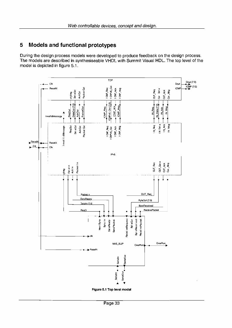
5 Models and functional prototypes
During the design process models were developed to produce feedback on the design process.The models are described in synthesiseable VHDL with Summit Visual HDL. The top level of themodel is depicted in figure 5.1.
(7:0)
P (7:0)
TCP
~,-.- Clk Dout
,...- ResetN a 0" a .>< '" '" ICMP~m' a If ",' ~ ~ 0"
8.>< '"a a;
~' ~ ~' ~'If ~ ~
J:J '".><
a', , ,
~ 8.>< u a a a~ ~ - - - -
6' 6'6'
~t:. '5 0"~ .>< '" g t:..'5 ~ '" .><
'5 0 " :::;;'" :i'5 S c:: 0, , c::
~0 0 m , 0.. 0.. , a;
~l'" .>< 0.. '" :::;; :::;; z Cl ~1ii .><~ :::;; ~ - ,
" :i ~ ~InvaliidMessage c:: Cl 0.. ~ :::;; ~
~
0" '" .>< '"" a a a a 0"_ .>< '" 8 ~ '"'" Ifa ~ ~ If :::;;'" 0" '" .>< z' z' ,'" ;;
~I Wi ~' ~' z' ~'" If 8 ~ .>< - -~ u -"0 ~ - ~ - -.-- -
etN 0;ResetN >c:
ik -Clk
IPv6
c: 0" '" '"- .><
c: - If 8 ~ ~c: q;
a', , ,
m'0; _ .>< aaa- .>< u
J:J 8~ ~c.... .............. ..... .CJ ··c·c······
P.~kAtln OUT Req
DataReadByteOut (7:0)
n.t.ln 17mBvteReceived
Ren()
tReceivePaeket
I r- - -" ~ >- q; ;;; a "0 ;;
">. "0 .>< " > .><m " '" u " " u
~ If 0" ·m ~;;'"
~ If ~ ~ "! "0 " >8 c: >Jl " ·m·m
~uu Ifelk If
NAS_SLlP OverRunOverRun
ResetN
c: '50'iii 16
~ ~
c: '5
~0
"~
en "en
~ReE
~
Figure 5.1 Top level model
Page 33

Web controllable devices, concept and design.
The top layer of the VHDL description contains the units of the protocol stack. The NAS_SLlPunit has a serial interface to the Internet (Serialln and SerialOut). The NAS_SLlP unit isconnected to the IPv6 unit, the signals between the NAS_SLlP and the IPv6 unit form theNetwork Abstraction Sub-layer Interface as described in section 4.1.2. The TCP unit containstest modules. This module generates a message to be sent and absorbs a received message.The top layer model is used to test the interaction between modelled units. Within each test acase is used that follows a specific path through the design.
ReceivePacket
ByteReeeived
ByteOut (7:0)
ReceiveRequest
NextByte
DataReady
Byteln (7:0)
SendPaeket
~~Re=set=-N-.- ResetN~'
~elk'-----.---r. elk ~
~
~
~ ~~ ~
Q)
~
SLIP
"-- ..elk Uart
"0;Q)
~ >
~Q. '0;,- u
Q) Ii!Q. 1Il
6
~ ~ .~'" - 1lQ) ~ Q)
II: ~ II:
WOverRun
E.~Q)(/)
Figure 5.2 Network Abstraction Sub-layer for a SLIP connection.
The NAS_SLlP unit consists out of a slip unit and a UART as depicted in figure 5.2. Thehierarchical description of the units within the SLIP_NAS unit allows reuse of these units. TheSLI P unit contains the models of the slip encoder and slip decoder.The UART unit contains the logic to receive and transmit data over a basic three wire serial link.The serial clock is generated within the UART. Altering a constant of the VHDL model will alterthe serial clock frequency.
Page 34

~-,-".
Web controllable devices, concept and design.
o.._~
_1111'- jt----1 ... l ll;SIoI l-----+OIk~ ~ dk K1ck+----f-t-+--1f----+---=--____f_'
i~jil~
t---------t::m n d l8RB0000 _
~:. :. ~ E_
., j,. j• • " I
~ .Figure 5.3 The IPv6 unit
The content of the IPv6 unit is depicted in figure 5.3. On the left-hand side the receiving units aredepicted and on the right hand side the transmitting units are depicted. The transmitting sidegets its data from the TCP unit. The X_Sus_In unit contains the data source of the X-bus. TheX_Sus_Controller generates the Xslot signal. The Xhandler2 unit is a model of an extensionhandler. The model of the extension handler does not contain a real extension header encoder,it just inverts the data signal. The IPv6 Encoder is used as output for the X-bus. The IPv6encoder is a model of the described design. The outputs of the left-hand side can be connectedto the inputs of the right hand side. This reduces simulation-processing time.
The left-hand side gets a message, either from the NAS or the right hand side. The IPv6decoder processes the received message. The IPv6 decoder output (defined in 'figure 4.5) is puton the X-bus. The extension handler is also a dummy extension handler that just inverts thepayload. When an error is found in the payload by the IPv6 decoder the invalid_message signalmade high in order to signal a pipeline flush. When the IPv6 decoder discovers a parameterproblem, it signals the ICMP unit. The ICMP unit then generates the ICMP parameter problemmessage.
The IPv6 unit does not contain a last minute length insertion unit or a configuration data unitbecause these where not modelled.
Page 35

Web controllable devices, concept and design.
ResetN
Clk
>.
'" "0
'" :; '"Glelk c 0 a:
L~Clk"0 '" '"'" ;;;Gl '"a: c c
Basis_A
----J ResetN ICMP (7:0)D
L.--J Clk :D ;; :;( :if '? -"Basis_A - ;:
a:1 ';;;:I.
ResetN Dout (7:0) ...ID~
... - =>=> '"o c 0
:D - -- c « ;: 6 :;t: 0
:;c- O -" 0>Gl I :I.,
Ula: <g E
I I
6 a. a. a. a.:::; :::; :::; :::;
to
~~ ~ ~ ~
,.;3 ;3 :;
'" 0c- O; -" -"Gl :I. l;la: c a.
Figure 5.4 The TCP unit.
The content of the TCP unit is depicted in figure 5.4. The TCP unit contains 2 units calledBasis_A, which absorb messages. The output D of Basis_A contains the last received byte. Theother unit generates one message from one file. The file name is a constant that can be adjustedto send different messages.
The modelled units were all simulated before and after synthesis, routing and placement. Sincethe design is not completed, a prototype could not be developed. When the design is completeda fully functional prototype can be tested.
The test environment would consist of a microcontroller connected to the protocol stack and aPC connected to the stack with a serial link. Fist the transmitter should be tested, byprogramming the microcontroller to send test messages and analysing the results at the PC.When the transmitter is fully functional and conform the protocol specifications the transmittercan be used for testing the receiver. The microcontroller is then programmed to transmit thestack to the PC for analyses.
At the moment of writing the IETF is starting to develop test schemes for Ipv6. Thesedevelopments are promising and could be used for testing the IPv6 layer.
Page 36

Web controllable devices, concept and design.
6 Conclusions and future work.
A web controlled device has to contain:
• A communication circuit to connect the device to the Internet.• The IP protocol• The TCP protocol• The telnet protocol• A textual command language to control the device
The protocol stack of the device has been implemented as dedicated hardware to reduce theload on the embedded processor. The organisation of a protocol stack encourages implementingthe protocol stack as a pipelined data processor. The current design includes:
• A general interface to communication devices. The design of the web controllable device istherefore media independent
• An IPv6 encoder and decoder to process IPv6 messages.• A dedicated bus to enable the processing of extension headers in order of appearance in the
message.• A last minute length insertion unit to overcome the causality problems in generating not fixed
length messages by a pipeline
Although IPv6 is not an Internet standard yet, it has been chosen because it will become anInternet standard in the near future and its specification is not likely to change. IPv6 will supporttraffic classes and authentication, these developments will be very useful in web controlleddevices.
Web controlled devices must contain a safety envelope to prevent dangerous situations as aresult of the Internet delay. The safety envelope ensures the safety of the device by restrictingthe control to safe transitions between stable situations.
The design of web controlled devices is not complete. AI lot of work has been done, but there iseven more work to be done:
• When the IETF publishes the RFC on traffic classes, the use of virtual circuits defined in thisRFC should be investigated and possibly a new class must be proposed.
• The modelling of Internet delay for controlled systems has to be investigated to developweb controlled devices in a regulating configuration.
• The communication of ICMP events between the ICMPv6 unit and all other units must beinvestigated.
• The structure of the unit that contains the configuration data should be investigated• The ICMPv6, extension handlers, TCP, telnet, configuration data unit and the interface to
the embedded system must be designed.• The IPv6 testing schemes should be studied when they are published by in a RFC.
Page 37

7 References
[TCP]
[IPv6]
[I PV6-ADDR]
[ICMPV6]
[SLI P]
[Comer]
[Bertsekas]
[RFC]
[Rail Road]
[I nterprophet]
Web controllable devices, concept and design.
Postel, J., ed., "Transmission Control Protocol - DARPA Internet ProgramProtocol Specification", RFC 793, USC/Information Sciences Institute,September 1981.
Deering, S. and R. Hinden, "Internet Protocol, Version 6, (IPv6)Specification", RFC 2460, December 1998.
Hinden, R. and S. Deering, "IP Version 6 Addressing Architecture", RFC2373, July 1998.
Conta, A. and S. Deering, "Internet Control Message Protocol (ICMPv6) forthe Internet Protocol Version 6 (IPv6) Specification", RFC 2463, December1998.
Romkey, J.L., "Nonstandard for transmission of IP datagrams over seriallines: SLIP", RFC 1055, Jun-01-1988.
Comer, Douglas E., "Internetworking with TCP/IP vol 1: Principles,Protocols and Architecture, Second edition", Prentice-Hall International,Inc. (ISBN 0-13-474321-0)
Bertsekas, Dimitri and Robert Gallager, "Data networks second edition",Prentiice-Hallinternational, Inc (ISBN 0-13-201674-5)
http://www.cis.ohio-state.edu/htbin/rfc/
http://rr-vs.informatik.uni-ulm.de/rr/gui2/
http://www.interprophet.com/tcpbw.html
Page 38