web viewthe design of this hydro-generator 50mva, ... it is designed for a small hydro electric...
TRANSCRIPT

DESIGN OF A HYDROGENERATOR FOR TROPICAL USE IN RURAL ENVIRONMENT; 50MV.A, 125rpm; 0.9pf
BY
JAMES OS
1

ABSTRACT
The constant need for uninterrupted power supply by various consumers, particularly in the rural communities has called for more ways in the design of alternative systems to meet this need. There are various sources of electrical power supply in which the use of a synchronous generator is inevitable, this even include the latest development in renewable energy technologies. There are two distinct types of synchronous generator and these are Hydro-generator and Turbo-generator.
A synchronous generator in principle is that electrical machine that converts mechanical energy into electrical energy which is supplied to load centers at various points.
The design of this hydro-generator 50MVA, 125rpm, 0.9 power factor is targeted for use in the rural areas of the tropics for which the prevailing temperature is taken care of; e.g. in Nigeria. It is designed for a small hydro electric power station and to be installed along the bank of River Niger in Nigeria. As farming is predominantly the trade of the people in this environment there will be room for irrigation and even fishing as a trade.
In principle the design gives the calculations of the parameters of the various components of the machine.
The parameters obtained in the mathematical design of this synchronous generator gave a reasonable efficiency curve which confirms the validity of all the parameters that were calculated for and those that were chosen for it.
It is therefore envisaged that if the generator is built and installed apart from meeting the need of the environment it will also perform at its fullest capacity carrying the loads effectively and efficiently.
2

1.0. INTRODUCTION
1.1. HISTORY OF HYDROELECTRICITY
History of hydroelectricity had been known to man as far back as the ancient times for the purpose of turning water wheels which are mostly used in saw mills, textile mills and even for grinding.
Civilisation has now brought about the use of turbines thus replacing the waterwheels. Further development of the use of turbines showed that it can be used to produce electricity thus giving birth to design and construction of hydro-generators. Hydro-electric power plant had been found to be economical, clean and somewhat reliable as form of renewable energy source.
Today there are various sizes of hydro-turbines for driving hydro-generators for the production of electricity.
The main principle of operation of hydro-electric power plant is that water from a reservoir under very high pressure falls on the turbine blades which then turn the synchronous generator arranged above the turbine. The falling water can again be recycled for other purposes like irrigation, fishing, transportation, etc., thus making hydro-electric energy to be economically viable. As a form of renewable energy source the cycle is such that the effect of the wind on the oceans, seas, rivers and streams carries evaporated water from them by the energy of the sun to form rain cloud. After a while the rain water in the cloud is then discharged as rain or snow on the ground and the water again flows into the oceans, seas, rivers and streams.
Generally abundant electrical energy potential is available along the Bank of River Niger to provide electricity to the rural areas therein. It is then evident that the most economic source of energy that will develop the areas is hydroelectric power system. This is the essence of this design when it is built and installed and bearing in mind the take-off of Ajaokuta Steel Complex which is just nearby.
Furthermore when this machine is installed in these rural areas along the River Niger there will be expansion of farm settlements through irrigation and well laid out settlements.
Presently there are two power stations en route River Niger and these are Kainji Hydro Power Station and Jebba Hydro Power Station. These two power stations had at no time run at full capacity and this means that they had never met the energy demand in the country.
The incapability can be said to be attributed to:
1. Lack of proper maintenance culture on the installed machines as at when due2. Old age of the installed generators
With this design modern day technology will be used both for the construction and operation when installed.
3

The economic independence of any Nation depends on the abundant and reliable supply of electrical power. The extension for this electrical power to all towns and villages alike play an important role in the economic independence and consequent Nation building and development.
Technology development of today has shown that the value of electrical energy in commercial, economic and in industries is advancing rapidly thus making electricity supply to find a place in all engineering and scientific researches for sustainable development.
In recent times electrical energy has improved the general standard of living of mankind worldwide. Consequently rigorous and profitable researches are going on for its improvement and development
In almost all the electric power stations there is at least one synchronous generator installed for the generation of electricity supplied to the consumers. The design of this generator has therefore become necessary as the load it will carry needs to be considered and even the prevailing climatic conditions of the area where it is to be installed.
This designed hydro-generator has all the conditions that can influence its maximum delivery. Its efficiency curve as shown in Figure 5 has shown this to be correct.
The rotor poles also give the required value of the main magnetic flux for the rated speed of the generator.
1.2. BRIEF HISTORY OF ELECTRICITY GENERATION IN NIGERIA
Electricity generation in Nigeria dates back to 1896 when the Public Works Department in Lagos was the sole distributor. The system of generation was by steam and diesel engines.
By the end of the Second World War in 1945 the Nigerian Government Electricity Undertaking was established to take over from the Public Works Department to see to the supply and distribution of electrical power to hinterland.
In 1950, Electricity Corporation of Nigeria was established since more town and villages were already enjoying supply of electricity. After the survey of hydro power potential in Nigeria the Niger Dam Development Authority was established to develop hydroelectric power on River Niger and hence a dam was built at Kainji. By 1972 the Electricity Corporation of Nigeria and Niger Dam Development Authority were merged to establish National Electric Power Authority which then was charged with the responsibility of generation, transmission and distribution of electricity all over the country.
As a result of power reform in the country the National Electric Power Authority became Power Holding Company PLC.
Presently the total installed capacity of 4200MW is hardly met as the generating capacity is 2300MW which is far below the expected demand of 80000MW nationwide. It is clear that the power utility company had not been able to meet the electricity demand in the country.
4

River Niger which flows from Futajalon Mountains in Guinea and discharges into the Atlantic Ocean through the Niger Delta in Nigeria has become a source of generating electricity through hydrogenating power plants in Kainji and Jebba.
5

2.0. DESIGN OF THE HYDROGENERATOR
Generally hydro-generators are slow motion salient pole synchronous machines which are put into rotation by hydraulic turbine. They are often installed vertically since they depend on fall of water under pressure from a height.
Figure 1. General Scheme of a Hanging Vertical Hydro-generator with two Direct Bearings
1. Stator 2. Rotor
3. Upper crosshead 4. Lower crosshead
5. Thrust bearing 6. Upper ball bearing
7. Lower ball bearing 8. Shaft
9. Basement 10. Turbine
6
10

The design of this particular hydro-generator is based on the consideration of its stability when in a suspended form of utilization with two guide bearings. The step bearing for it will have to be arranged on the upper crosshead which will rest on the housing of the rotor. The lower guide bearing will have a general oil bath with the step bearing.
At the upper part of the generator will be arranged slip rings and a regulating generator. The rate of deceleration using mechanical brakes is made to be about 25% of the rated value. This will be attained by blowing air under a pressure of (7-8) atmospheres into the mechanical brakes. The mechanical brakes can equally be used as hydraulic jacks for lifting the rotor during maintenance.
2.1. STATOR CORE
The stator core of this generator will be of a welded joint construction of six parts so as to make transportation more convenient. It will be a collection of pressed segments of electro-technical cold rolled steel which had been painted with varnish. The thickness of the steel is 0.5mm and has a specific energy loss of about 1.32W/kg.
The dimensions of the stator core are obtained using the number of slots per pole per phase as base.
q = Z/2pm
By varying the value of ‘q’ between 3.0 and 3.5 the appropriate value for the dimensions of the stator core are obtained.
Number of slots per pole per phase: q = 3.125
Number of slots in the stator: Z = 450
Internal diameter of stator core: Di = 724cm
External diameter of stator core: Da = 791cm
Pole pitch: ι = 47.4cm
Air gap: δmin = 1.67cm; δmax = 3.0cm
Designing value of the air gap δ = 2.33cm
Ampere turns: A = 544A/cm
Length of stator core: la = 137cm
Width of stator core: ba = 3.19cm
Width of slot: bs = 1.86cm
7

Figure 2. Slot of Stator with Winding
2.2. STATOR WINDING
The stator winding is to be arranged in the slots and protected by wedges. The winding will be double layered, wave form and of two bars. The bars are of rectangular cross-section with fibre glass insulation in thermal reactive varnish. For rigidity of the end connectors bandaged rings from nonmagnetic steel are to be used.
2.3. ROTOR CORE
The rotor core will consist of two distinct components:
- A rim- A framework with magnetic poles securely bolted on the lining on which it will
sit.
The rim and framework can always be loosened when excessively hot.
The 48 magnetic poles with winding sit on the rotor core. They are collection of laminated steel sheets of thickness 1.5mm and are tightened by studs. The core of these magnetic poles is insulated from the main magnetic field winding by glass compound, asbestos and two washers of fibre glass. This winding is of copper of special cross-section which will allow increase in surface heat emission. The supply of electric current to the winding from the contact rings will be made possible using pairs of electric bars.
8

Figure 3. Dimension of the Magnetic System
The dimensions of the magnetic poles are:
Height of the magnetic pole: hp = 27cm
Length of the magnetic pole: lp = 137cm
Width of the magnetic pole: wp = 25cm
9
Da Diameter of stator
Di Internal diameter of stator
bp width of pole
hp height of pole
bs width of slot
hs height of slot
δ air gap
hp
hs
bs

3.0. CHOICE AND TYPE OF WINDING FOR THE HYDROGENERATOR
The wave winding from copper rod is to be used for this design while the number of active conductor in each slot will be two. The wave winding is chosen because it is sequential in all conditions when considering rigidity and reliability of insulation.
3.1. WINDING PARAMETERS
For the calculation of the parameters of the winding some parameters are given initial value and later their exact value found. An initial value is given to the winding pitch reduction factor ‘β’ so as to find the value of the winding pitch. Its exact value is then used to calculate for the value of the winding factor which is very important during the design of hydro-generators. Using this initial value of β = 0.833 the winding pitch will be,
y = βZ/2p = 0.833*450/48 = 7.88
Since y has to be a whole number y = 8
Hence exact value of β will be
β = 2py/Z =48*8/450 = 0.8533
Using this value of β the winding factor is found to be kwf = 0.935
With the value of magnetic induction in the air gap to be Bδ = 0.772T the parameters of the slots are:
Height of slot hs = 17.5cm
Width of slot bs = 1.86cm
Width of copper bcu = 0.81cm (since there are two, then bcond = 4.05mm
The copper rods to be used are of different height hence there will be transposition and consequently the number of conductors in one rod will be
N = Ia/Jaqa = 1375/2.94*11.1 = 42.13
Since the number of conductor in a rod should be a multiple of the number of slots, hence
N = 45
Here Ia is the current in one parallel path
Ja is the current density in the stator winding
qa is the cross-sectional area of the conductor
The magnetic flux per pole is Φ = 0.4wb taking the number of coils in one phase to be 75
10

4.0. PARAMETERS OF OPEN CIRCUIT
The open circuit parameters of any electrical machine often give the possibility and opportunity to know its behaviour. With respect to this hydro-generator after careful selection and calculation of its open circuit parameters, the open circuit characteristics as seen in Fig.4.1 show that all its parameters are appropriate.
The process for this is calculation of the parameters of each component parts of the stator when the generator is on no load. The major parameters used for the drawing of the characteristics are:
Magnetic flux of excitation on one pole Φ1 = 0.4wb
Magnetic flue entering the external surface of the pole boot Φ2 = 0.355wb
Magnetic flux in the poles Φp = 0.55wb
Magnetic induction in the air gap Bδ = 0.7512T
Magnetic induction in the stator core Ba = 1.1601T
Magnetic induction in the stator teeth Bt = 1.6664T
Magnetic induction in the pole core Bp = 1.651T
The magnetic flux intensity is a function of the magnetic induction in the component parts. Hence
Magnetic flux intensity in the stator teeth Ht = 50A/cm
Magnetic flux intensity in the stator core Ha = 3.71A/cm
Magnetic flux intensity in the pole core Hp = 47.6A/cm
Using these values the values of the magneto-motive force of the component parts are calculated and consequently used to draw the open circuit characteristics.
Magneto-motive force of the air gap Fδ = 0.16δkδBδ = 0.16*2.333*1.132*0.7512*104
= 31742A
Magneto-motive force of the teeth of stator Ft = 1660A
Magneto-motive force of the poles Fp = 1834A
Magneto-motive force of the stator core Fa = 188A
Magneto-motive force at the joint Fj = 826A
Total magneto-motive of the open circuit Fo = Fδ + Ft + Fa + Fp + Fj
Fo = 31742 + 1660 + 188 + 1834 + 826 = 36250A
11

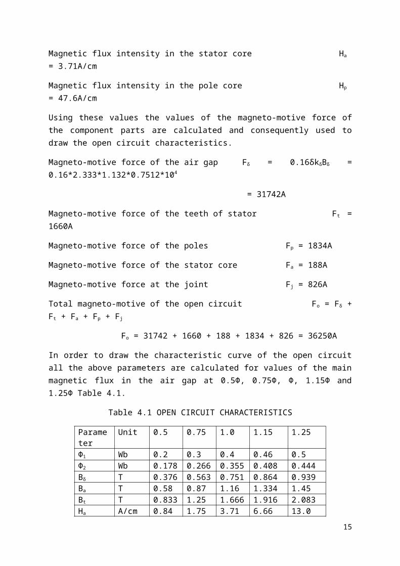
In order to draw the characteristic curve of the open circuit all the above parameters are calculated for values of the main magnetic flux in the air gap at 0.5Φ, 0.75Φ, Φ, 1.15Φ and 1.25Φ Table 4.1.
Table 4.1 OPEN CIRCUIT CHARACTERISTICS
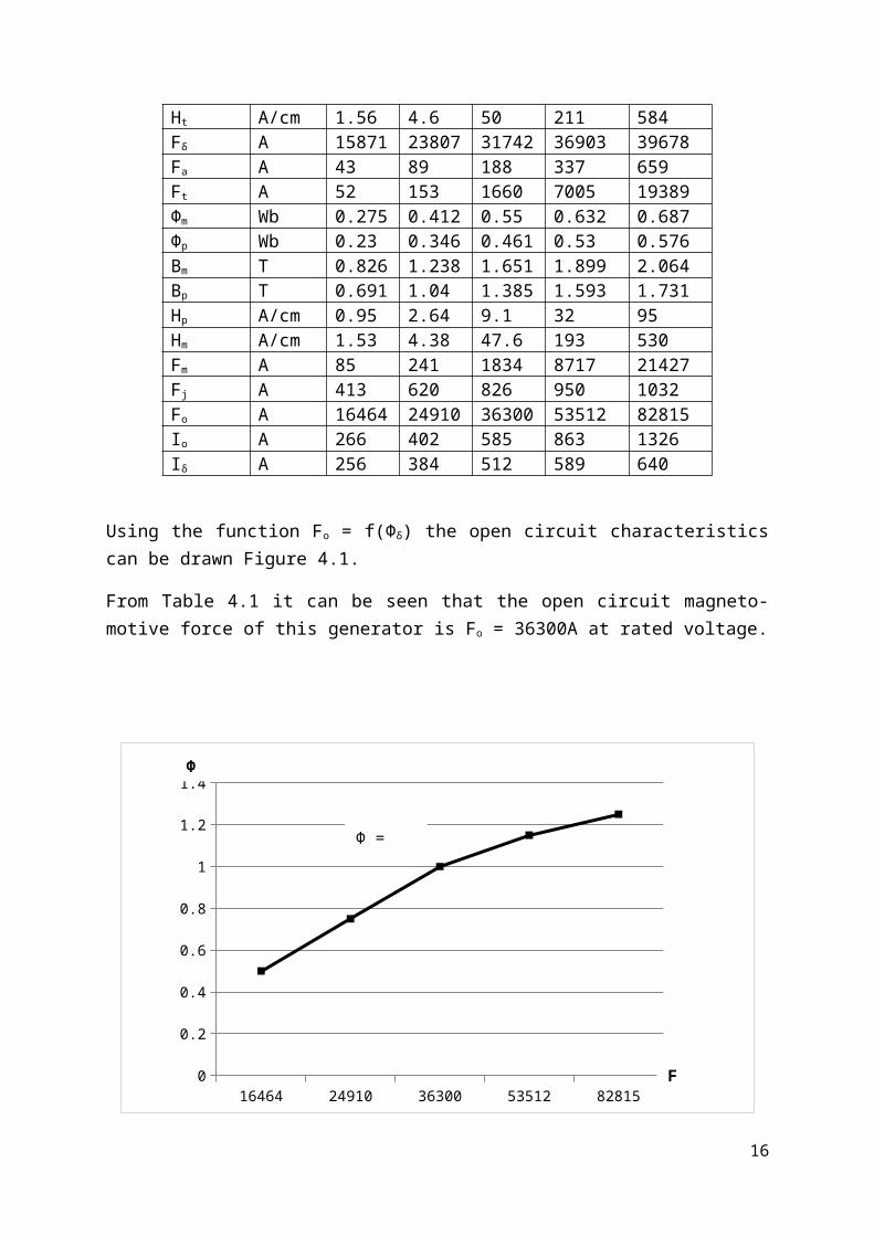
Parameter Unit 0.5 0.75 1.0 1.15 1.25Φ1 Wb 0.2 0.3 0.4 0.46 0.5Φ2 Wb 0.178 0.266 0.355 0.408 0.444Bδ T 0.376 0.563 0.751 0.864 0.939Ba T 0.58 0.87 1.16 1.334 1.45Bt T 0.833 1.25 1.666 1.916 2.083Ha A/cm 0.84 1.75 3.71 6.66 13.0Ht A/cm 1.56 4.6 50 211 584Fδ A 15871 23807 31742 36903 39678Fa A 43 89 188 337 659Ft A 52 153 1660 7005 19389Φm Wb 0.275 0.412 0.55 0.632 0.687Φp Wb 0.23 0.346 0.461 0.53 0.576Bm T 0.826 1.238 1.651 1.899 2.064Bp T 0.691 1.04 1.385 1.593 1.731Hp A/cm 0.95 2.64 9.1 32 95Hm A/cm 1.53 4.38 47.6 193 530Fm A 85 241 1834 8717 21427Fj A 413 620 826 950 1032Fo A 16464 24910 36300 53512 82815Io A 266 402 585 863 1326Iδ A 256 384 512 589 640
Using the function Fo = f(Φδ) the open circuit characteristics can be drawn Figure 4.1.
From Table 4.1 it can be seen that the open circuit magneto-motive force of this generator is Fo = 36300A at rated voltage.
12

16464 24910 36300 53512 828150
0.2
0.4
0.6
0.8
1
1.2
1.4
Figure 4. Magnetization curve of Hydro-generator 50MVA, 125rpm, 0.9pf
The synchronous reactances of the generator are calculated on the assumption that it is short circuited. Thus the following values were obtained for these important parameters of the synchronous reactances.
Synchronous reactance along the direct axis xd = 0.69pu
Synchronous reactance along the cross axis xq = 0.4754pu
Short circuit ratio SCR = 1.67
Consequently the total sum of magneto-motive force for a rated load at zero power factor is
FT = 88120A
5.0. ENERGY LOSS AND EFFICIENCY
13
Φ = ƒ(F0)
Φ
F0
All electrical machines dissipate energy in the form of heat. By this loss of energy the output power becomes reduced thus making the machines not to be 100% efficient.
In rotating electrical machines there are two distinct forms of energy losses and these are:
i. Main losses which are as a result of electromagnetic and mechanical processesii. Additional losses which are as a result of secondary occurrences
The main energy losses are again classified into:
i. Electrical losses which are losses in the windings due to flow of currentii. Magnetic losses which are due to the effect of magnetic flux on the coresiii. Mechanical losses which are due to rotation
As a result of the above losses it became necessary to calculate these losses for this hydro-generator and the following values were obtained.
Losses in the stator core during open and short circuit voltage Qa = 75.5kW
Losses in the stator teeth Qt = 79.6kW
Losses due to ventilation Qv = 130kW
DC losses in the stator winding Qw = 230kW
Short circuit losses during rated current Qsc = 278kW
Losses in excitation during rated load, rated voltage and
rated power factor Qe = 197kW
Losses in the thrust bearings QB = 106kW
The efficiency of the hydro-generator under rated load is then calculated from
η=1−[ ⅀QP1Cosφ−⅀Q ]=1− 967
50000∗0.9−957=0.97 .92
η = 97.92%The efficiency curve for this hydro-generator is as shown in Fig.5.1 using the Table below.
Load 0.25 0.5 0.75 1.0 1.25η 95.36 97.28 97.78 97.92 97.9
From calculations
The heating effect on the surrounding air is given θ = 24.93oC.
Increase in temperature of stator core steel θfe = 40.94oC
14
Increase in temperature of stator winding θs = 47.44oC
Increase in temperature of field winding θf = 64.75oC
0.25 0.5 0.750000000000001 1 1.2594
94.5
95
95.5
96
96.5
97
97.5
98
98.5
Figure 5. Efficiency of Hydro-generator 50MVA, 125rpm, 0.9pf
6.0 MECHANICAL DESIGN
15
η = f (P2)
P2
η
The mechanical design is based on the fact that there is rotation and hence each component parts of this hydro-generator is considered.
6.1 ROTOR
Majorly this is the rotating part of the generator with the magnetic poles also rotating with it.
Basically the rotor functions as
i. Inductor which forms a magnetic field of excitationii. Ventilator which gives the necessary thrust for ventilationiii. Flywheel which allows stability of operationiv. Braking disc during frictional brake
The rim of the rotor of this generator has eight segments for easy transportation. The following dimensions are vital in the mechanical design.
Length of rim: 164cm
Mean diameter of rim: 600cm
Centrifugal force of rim: 249200kg/cm
Moment of gyration of rim: 9377m2
Weight of rim per unit length: 888kg/cm
Weight of the magnetic pole per unit length: 415,84kg/cm
Weight of the rim with the magnetic poles: 216T
Total sum of all bending moment 7040kg/cm
Some calculated values can only be appreciated by considering cross-section of some parts of the generator. Including these will make this paper too lengthy for the time limit.
All of these other calculated values will be used during construction.
7.0. CONCLUSION
16

This designed hydro-generator for small hydro-electric power station can be said to satisfy all the technical demands as given by the data obtained during its design. Its construction will be in accordance with the present day technology.
The construction of this hydro-generator will be seen to satisfy safety techniques. The transient reactance obtained is very small 0.2793p.u.which also proves the quality of the machine.
This then mean that the hydro-generator when constructed will meet the demand in any community it will be installed.
8.0. REFERENCES
17
1. AI Voldek, Electrical Machines 1964, Moscow Publisher
2. MV Deshpande Electrical Machines, 1994, Wheeler Publishing
3. AI Abramof and AV Ivanov Smolensky, Design of Hydro-generators and Synchronous Compensators, 1978, High School, Moscow
4. Ion Boldea, Synchronous Generators, CRS Publishers 2005
5. Ion Boldea, Synchronous Generators (the Electric Generators Handbook), CRS Publishers 2006
6. Jack Holmes Walker, Large Synchronous Machines Design, Manufacture and Operation, Clarendon Press 1981
7. Charles Concordia, Synchronous Machines, Wiley Publishers 1951
8. UA Bakshi, MV Bakshi, DC machines and Synchronous Machines, Technical publications 2009
18