week 14 - simple pendulum
TRANSCRIPT

Week 14 The Simple Pendulum
1. Scope
1.1 Goal
Conduct experiment to study the simple harmonic motion of an oscillatory pendulum and analyze and interpret the data
1.2 Units of measurement to use
United States customary units
1.3 Safety Concerns
Students should maintain a minimum of 4 feet distance from the apparatus while pendulum is in motion as shown below.
2. Reference Documents 3. Terminology
• Include in procedure but leave empty for faculty to fill in
4. Summary of Test Method
Newton’s Law of Gravity and law of conservation of energy will be demonstrated by conducting an experiment on the simple harmonic motion of an oscillatory pendulum. The length of the pendulum and mass attached to end of pendulum is adjusted. By using the built in scale, the pendulum is released from a specific angle. At the time of release of the pendulum, an existing LabVIEW program will be used to measure voltage over time. The encoder output is converted into a digital signal by use of a data acquisition device. Using the data obtained, the total potential and kinetic energy of the mass at any given point in time can be estimated.
5. Apparatus
Standard setup Pendulum masses (Aluminum cylinder, Aluminum cube, Steel cylinder, Steel cube) 1 Set screw Slider system #14 (Includes slider, Subassembly of encoder, pendulum rod) Encoder Wiring
7. Sampling, Test Specimens
There will be five experimental runs in total. Two variables can be changed to obtain unique data for each experimental run: the mass, location of mass along the pendulum rod. The four objects differ in size, shape and mass. A set screw is used to secure the mass in location. The length of the pendulum rod can also be varied at the pivot point. The encoder will automatically begin counting the number of revolutions once the pendulum is released from a specific angle. The data is converted to a digital signal by use of the data acquisition device and is communicated to the student via a simple user interface by employing the LabVIEW software program. The data in the form of position of mass vs. time in an Excel file.
8. Preparation of Apparatus
Step 1: Setup upper post segment in vertical configuration Step 2: Adjust front and side adjoining strips (strips #1, #2) along the vertical post using the 1/8 inch wrench tool to secure the post in position as shown below Step 3: Connect back support to vertical post as shown below. Using the 5/32 wrench tool, tighten bolts to secure in place.

Step 4: Connect slider system #14 to right face of post as shown below. Position such that the bottom surface of the slider system aligns with 0” on the post’s scale Step 5: Connect ‘Encoder Wiring’. Plug USB to PC and other side to the slot at the bottom of the encoder as shown below.
Step 6: Log in to PC. Open LabVIEW program ‘Week 14 – Simple Pendulum’. Step 7: Confirm that encoder USB has been recognized.
Measuring tape to measure the length Till top surface of the mass Aluminum cube, cyl Steel cube, cyl
9. Calibration & Standardization
No calibration needed
10. Conditioning
The encoder is a counter and tracks number of degrees the pendulum moves in each direction. Data is collected and shown in the LabVIEW graph at the point in time when an increment or decrement in angle takes place.
11. Procedure
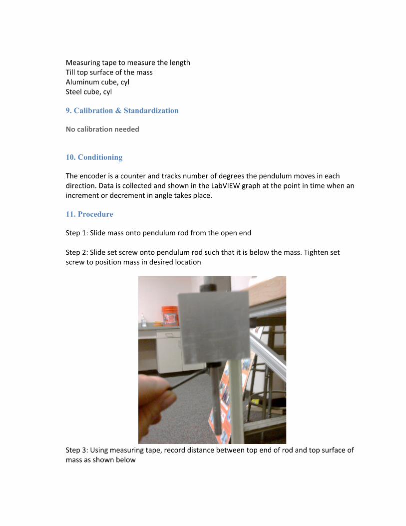
Step 1: Slide mass onto pendulum rod from the open end Step 2: Slide set screw onto pendulum rod such that it is below the mass. Tighten set screw to position mass in desired location
Step 3: Using measuring tape, record distance between top end of rod and top surface of mass as shown below

Step 4: In LabVIEW program, select ‘Start’ Step 5: Raise pendulum to desired height as shown below.

Step 6: Release pendulum. (Ensure no class mates or team members are within 4’ of the post due to safety reasons)
Step 7: Remain outside of the pendulum’s line of sight until it reaches to a complete halt.
12. Calculation/ Interpretation of Results
“This portion of lab is to be completed on Wednesday”
13. Report
“This portion of lab is to be completed prior to deadline after class hours”
14. Precision & Bias
The estimated uncertainty associated with data collected by the encoder is +/-‐ 0.5 degrees as it is a counter and tracks increments of one degree.