week 6 journal
DESCRIPTION
Digitalization process which include paneling and prototypingTRANSCRIPT
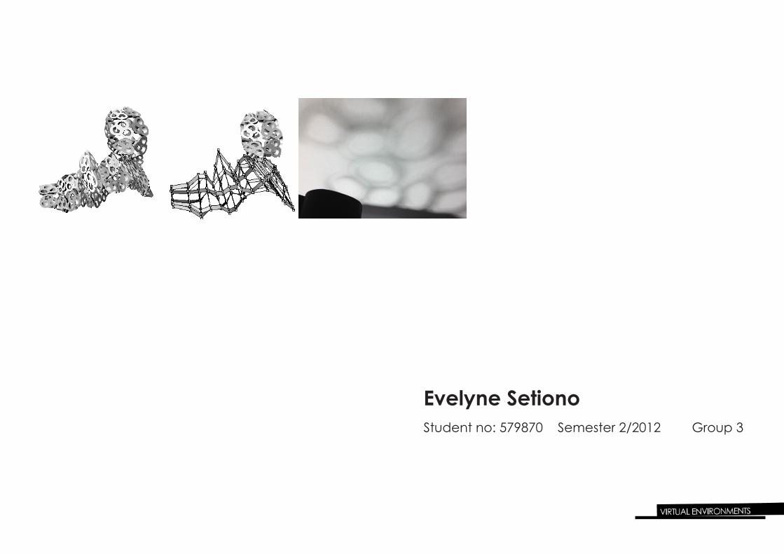
Evelyne SetionoStudent no: 579870 Semester 2/2012 Group 3
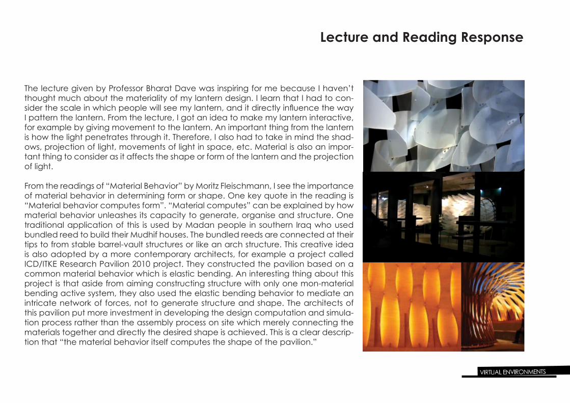
The lecture given by Professor Bharat Dave was inspiring for me because I haven’t thought much about the materiality of my lantern design. I learn that I had to con-sider the scale in which people will see my lantern, and it directly influence the way I pattern the lantern. From the lecture, I got an idea to make my lantern interactive, for example by giving movement to the lantern. An important thing from the lantern is how the light penetrates through it. Therefore, I also had to take in mind the shad-ows, projection of light, movements of light in space, etc. Material is also an impor-tant thing to consider as it affects the shape or form of the lantern and the projection of light.
From the readings of “Material Behavior” by Moritz Fleischmann, I see the importance of material behavior in determining form or shape. One key quote in the reading is “Material behavior computes form”. “Material computes” can be explained by how material behavior unleashes its capacity to generate, organise and structure. One traditional application of this is used by Madan people in southern Iraq who used bundled reed to build their Mudhif houses. The bundled reeds are connected at their tips to from stable barrel-vault structures or like an arch structure. This creative idea is also adopted by a more contemporary architects, for example a project called ICD/ITKE Research Pavilion 2010 project. They constructed the pavilion based on a common material behavior which is elastic bending. An interesting thing about this project is that aside from aiming constructing structure with only one mon-material bending active system, they also used the elastic bending behavior to mediate an intricate network of forces, not to generate structure and shape. The architects of this pavilion put more investment in developing the design computation and simula-tion process rather than the assembly process on site which merely connecting the materials together and directly the desired shape is achieved. This is a clear descrip-tion that “the material behavior itself computes the shape of the pavilion.”
Lecture and Reading Response

Digitalization
As can be seen from the pictures on the right, the digital model doesn’t resemble accurately with the clay model. It was too large and out of size. I analyzed the source of the problem. It turned out that I didn’t scale the embedded orthoganal pic-tures right, and I didn’t arrange the sections within the picture box. I decided to redo it and made the model as accurate as possible. I aligned the sections on the front view according to the con-tours that I’ve made on the clay model.

Digitalization
After re-aligning the sections on front view mode, I also aligned them in per-spective mode to see whether they are in order or not. The next step was lofting the aligned sections together to see what form would it make. The first lofting result was not perfect as there were some bulky parts on some sections. I tried to edit some parts to eliminate the bulk on the model. I’ve successfully made the model less bulky, however there were some twisting remained on the model. I tried to fix it by using record history before lofting to make it easier to edit after lofting. The changes made will automatically displayed on the model. The image above was the result of editing.
Digitalization
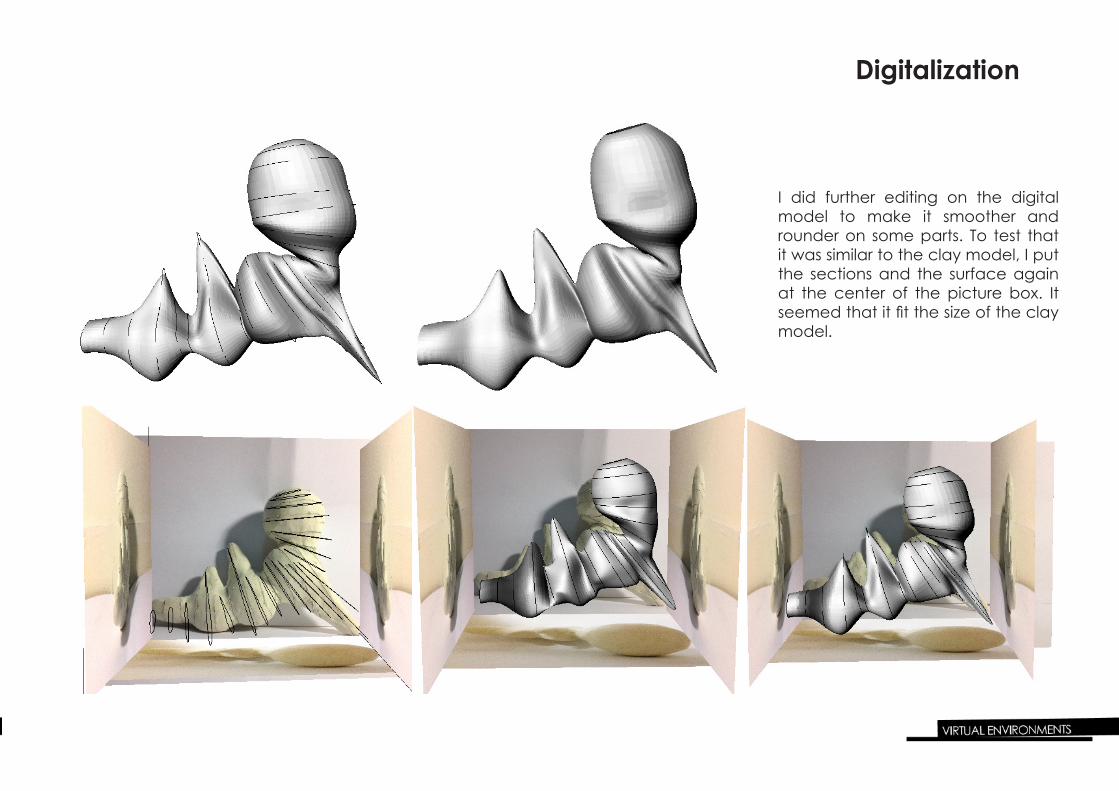
I did further editing on the digital model to make it smoother and rounder on some parts. To test that it was similar to the clay model, I put the sections and the surface again at the center of the picture box. It seemed that it fit the size of the clay model.

Paneling Process
2D Paneling Experiment
I experimented using several basic 2D patterns which were available on Rhino. I did this to see the nature of the shape of the model and to familiarize myself with the paneling tool. To create paneling grid on the surface of the model, I used Surface Domain Number and set the number of spans into 30 in u direction and 15 in v direction. The results are shown below.
Triangular BoxX Tribasic
Wave Brick Angelbox
Box
Diamond

Paneling Process
3D Paneling Experiment
I also experimented with the panel 3D grid. I did this by ofsetting the points on the surface by 20. The results are shown below.
3Dbox Partition Wedges
Pyramid 1 Pyramid 2

Paneling Process2D Custom Paneling
Bubbles pattern Disc pattern
These are my experiments in using 2D custom paneling. I designed bubbles pattern and disc pattern to see how round shapes affect the form of the model. The model turned out to be a little bit abstract and lose its original form. I could improve it by adding more points on the model when paneling.

Paneling Process3D Custom Paneling
Here I tried to made use of 3D custom paneling by using cuboid pattern. I set the distance between u and v as 2 to give space between the cuboids. The result is a failure be-cause the model was broken apart into different segments and didn’t bind together as one whole body.
Sphere pattern
The second attempt I made is using sphere as the pattern. I explored the function of 3D custom variable and from the distribution method option, I chose PointAttractors to ar-range the pattern bigger when it is nearer to the attractor point. I placed the point on top of the upmost part of the model so that larger spheres would be on top and smaller spheres would be on the bottom. I wanted to relate these patterns to my original concept of effervescence where the bubbles increase in size as they went up, however, this was also a failure because the base part were smaller as they were far from the attractor point even though it was supposed to increase in size to suit the concept.

3D Custom Paneling
Paneling Process
I began to think back to my process of effervescence in champagne, especially in the formation of bubbles on the surface. The bubbles combined together into several frame-work of bubbles. I tried to represent it into a more basic pattern which is called as trefoil where there were 3 cirles chained together. Trefoil symbols are usually used in gothic architecture as ornaments on window or door frames and walls. They are also used in other designed objects, such as lamp and jeweleries.
Trefoil patternThis is a trial in applying trefoil symbol on my model.

Prototyping
Lighting Effect
I made use of black card paper which is easy to bend, however quite diffcult to shape a perfect circle as it is likely to bend in 90 degrees angle. The shadows obtained represent formation of bubbles which relate to my original concept.