weir minerals division suction side considerations for … minerals division 7 npsh tests on...
TRANSCRIPT
Weir Minerals Division
Excellent Minerals Solutions
Commercial in Confidence Confidential Information and Copyright This document contains information which is protected by copyright and is confidential to companies forming the Weir Minerals Division. It should not be copied or disclosed (in whole or in part) to parties other than the recipient without the express written permission of Weir Minerals Division authorized personnel.
Presented to:
Prepared by:
Date: November 4, 2011
Suction Side Considerations for Slurry and Froth Pumping
Calgary Pump Symposium November 2011
Peter Williams

2 Weir Minerals Division
NPSH – is that all we need to consider?
For most mineral slurries, NPSHA is not much of a consideration unless there isn’t enough, when it becomes a big deal.
In most mining operations, the slurries are relatively cool, the pump sizes & flows are relatively low, and the suctions are flooded. Ignoring NPSH usually doesn’t cause a problem.
However, when pumps are large, and flows are high, and temperatures are elevated, it cannot be ignored. These situations can occur in large mill circuits and in oil sands HT & Tails.
Air entrainment also causes suction problems that inter-relate with NPSH, but are not strictly an NPSH problem.
The NPSH portion is the work of Dr. Aleks Roudnev, Manager R&D- Applied Hydraulics, Weir Minerals North America, and vice-chairman of HI Slurry Pump Standards Committee.
NPSH:
3 Weir Minerals Division
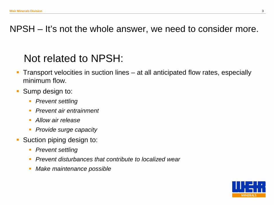
NPSH – It’s not the whole answer, we need to consider more.
Transport velocities in suction lines – at all anticipated flow rates, especially minimum flow.
Sump design to: Prevent settling Prevent air entrainment Allow air release Provide surge capacity
Suction piping design to: Prevent settling Prevent disturbances that contribute to localized wear Make maintenance possible
Not related to NPSH:

4 Weir Minerals Division
INTRODUCTION – Part 1
For slurries of settling type NPSH required by pump practically equals to that on water
For viscous liquids, including Bingham Plastic mixtures, NPSH required by pump is not equal to that on water
Free air at pump inlet leads to increase in required NPSH
Current view:

5 Weir Minerals Division
HI Slurry Pump Standard
The ANSI/HI 12.1-12.6 Slurry Pump Standard deliberately offers little specifics relative to NPSH performance - NPSH required by the pump when handling slurry will increase, in most cases.

6 Weir Minerals Division
NPSH TESTS ON SETTLING SLURRY
Mashin (1954) Herbich and Cooper (1971) Kirillov (1984) Addie et al. (1999)
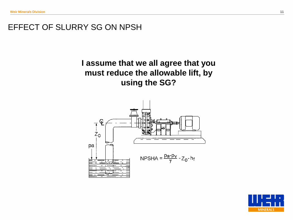
Governing equation NPSH = (pa - pv)/ρg + Z0 - hf
NPSHRm = NPSHRw
NPSH required on water and sand slurry, 5-inch pump, 330 mm impeller 1450 RPM (from Mashin)
0
1
2
3
4
5
30 50 70
Flow Rate, l/s
NPSH
R, m
w ater
sand slurrydensity 1150kg/m3,d50=1.0mmAverage value
BEP flow rate

7 Weir Minerals Division
NPSH TESTS ON SETTLING SLURRY
10
12
14
16
18
20
22
24
26
28
0 2 4 6 8 10 12
NPSH, m
Hea
d, m
water
density 1070kg/m3,d50=0.96 mmdensity 1180kg/m3,d50=0.96 mmdensity 1080kg/m3,d50=1.80 mmNPSH fullcavitation
NPSHRm = NPSHRw
0102030405060708090
100
0.01 0.1 1 10 100
Particle size (d) mm
Cum
ulat
ive
% p
assi
ng
sand d50=0.20 mm gravel d50=0.96 mm
gravel d50=1.80 mm gravel d50=6.15 mm
NPSH curves for water-gravel mixture, 5-inch pump, 1300 RPM
Particle size distributions for sand and gravel mixtures (from Kirillov)

8 Weir Minerals Division
REQUIRED NPSH AT 3% HEAD DROP
24
25
26
27
28
29
0 2 4 6 8
NPSH, m
Hea
d, m
water
density 1025kg/m3density 1060kg/m3density 1250kg/m3NPSH 3%
NPSH const
Normalized to Hr
22
23
24
25
26
27
0 2 4 6 8NPSH, m
Hea
d, m
water
density 1040kg/m3density 1085kg/m3density 1280kg/m3NPSH 3%
NPSH const
Normalized to Hr
19
20
21
22
23
0 2 4 6 8
NPSH, m
Hea
d, m
water
density 1035kg/m3density 1085kg/m3density 1250kg/m3NPSH 3%
NPSH const
Normalized to Hr
80% BEP flow rate
BEP
120% BEP flow rate
Sand Slurry

9 Weir Minerals Division
21
22
23
24
25
26
27
0 5
NPSH, m
Hea
d, m
density 1070 kg/m3,d50=0.96 mm
density 1180 kg/m3,d50=0.96 mm
density 1080 kg/m3,d50=1.80 mm
NPSH 3%
NPSH const
Normalized to Hr
REQUIRED NPSH AT 3% HEAD DROP
Gravel Slurry
80% BEP flow rate
BEP
120% BEP flow rate
23
24
25
26
27
28
29
0 5
NPSH, m
Hea
d, m
water
density 1088 kg/m3,d50=0.96 mm
density 1160 kg/m3,d50=0.96 mm
density 1110 kg/m3,d50=1.80 mm
NPSH 3%
NPSH const
Normalized to Hr
19
20
21
22
23
0 2 4 6 8
NPSH, m
Hea
d, m
density 1080 kg/m3,d50=0.96 mmdensity 1160 kg/m3,d50=0.96 mmdensity 1080 kg/m3,d50=1.80 mmdensity 1060 kg/m3,d50=6.15 mmNPSH 3%
NPSH const
Normalized to Hr
10 Weir Minerals Division
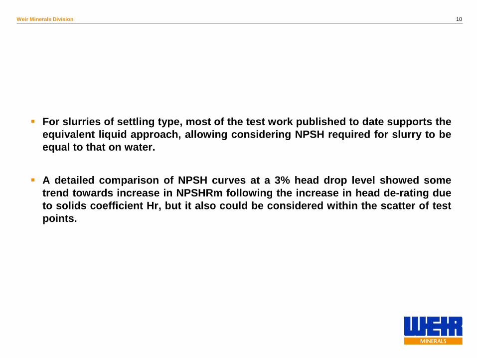
For slurries of settling type, most of the test work published to date supports the equivalent liquid approach, allowing considering NPSH required for slurry to be equal to that on water.
A detailed comparison of NPSH curves at a 3% head drop level showed some trend towards increase in NPSHRm following the increase in head de-rating due to solids coefficient Hr, but it also could be considered within the scatter of test points.
11 Weir Minerals Division
EFFECT OF SLURRY SG ON NPSH
I assume that we all agree that you must reduce the allowable lift, by
using the SG?
12 Weir Minerals Division
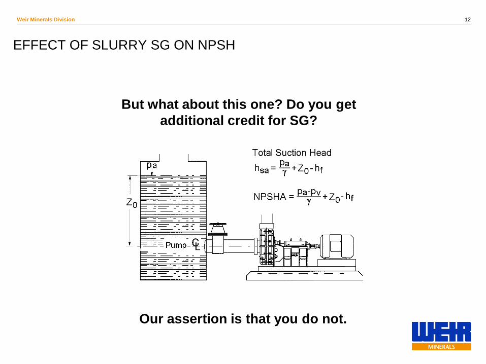
EFFECT OF SLURRY SG ON NPSH
But what about this one? Do you get additional credit for SG?
Our recommendation is that you do not.
Our assertion is that you do not.

13 Weir Minerals Division
NPSH TESTS ON BINGHAM PLASTIC MIXTURES
Orlov (1955) Mogilevsky (1972) Herbich (1975) Ladouani et al. (1995)
Reference equation NPSH = (pa - pv)/ρg + Z0 - hf
NPSHRp ≠ NPSHRw
0
2
4
6
8
10
12
25 30 35 40 45 50 55 60 65 70
Flow rate Q, l/s
NP
SH
3%
, m
density 2340 kg/m3 density 2250 kg/m3density 2140 kg/m3 density 2070 kg/m3NPSHR on water BEP line
H-Q and NPSH performance on dense medium, 4” side inlet pump, 4 vane closed impeller 335 mm diameter, 1450 RPM (from Mogilevsky)
0
5
10
15
20
25
30
35
40
0 10 20 30 40 50 60 70 80
Flow rate, l/s
Hea
d, m
0
10
20
30
40
50
60
70
80
Effi
cien
cy, %
water magnetite density 2030 kg/m3magnetite density 2400 kg/m3 ferrosilicon density 3300 kg/m3
14 Weir Minerals Division
NPSH TESTS ON BINGHAM PLASTIC MIXTURES
02468
101214
20 25 30 35 40 45 50 55 60
Flow rate Q, l/s
NPS
H 3
%, m
density 2450 kg/m3 density 2320 kg/m3density 2170 kg/m3 NPSHR on waterBEP line
02468
1012
20 30 40 50 60
Flow rate Q, l/s
NPS
HR
3%
, m
density 2400 kg/m3 density 2200 kg/m3NPSHR on water BEP line
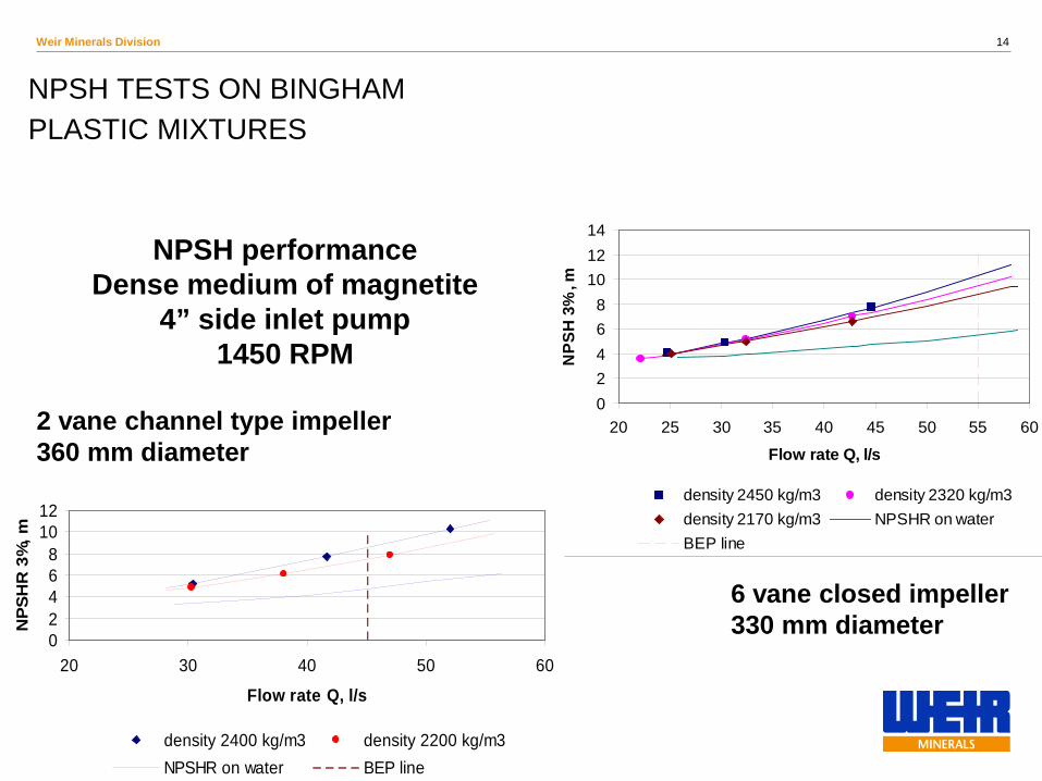
NPSH performance Dense medium of magnetite
4” side inlet pump 1450 RPM
6 vane closed impeller 330 mm diameter
2 vane channel type impeller 360 mm diameter
15 Weir Minerals Division
BINGHAM PLASTIC MIXTURE FLOW AT PUMP INLET
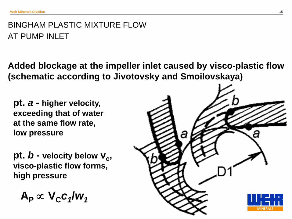
pt. a - higher velocity, exceeding that of water at the same flow rate, low pressure pt. b - velocity below vc, visco-plastic flow forms, high pressure
Added blockage at the impeller inlet caused by visco-plastic flow (schematic according to Jivotovsky and Smoilovskaya)
AP ∝ VCc1/w1

16 Weir Minerals Division
APPROXIMATION OF TEST RESULTS
1.0
1.2
1.4
1.6
1.8
2.0
2.2
0.00 0.01 0.02 0.03 0.04 0.05
Added blockage coefficient (vcc1/w1
2)
NPS
HR
p/N
PSH
Rw peat slurry
magnetite densemedium
approximation,Eqn (8)
NPSHP = NPSHW (1 + 24 vC c1/w12) Eqn 8

17 Weir Minerals Division
COMPARISON OF CALCULATED RESULTS WITH TEST
0.0
2.0
4.0
6.0
8.0
10.0
12.0
25 30 35 40 45 50 55 60 65 70Flow rate Q, l/s
NPSH
3%
, m
Density 2340 kg/m3testDensity 2340 kg/m3Eqn 8Density 2070 kg/m3testDensity 2070 kg/m3Eqn 8NPSHR on water
NPSH required on dense medium of magnetite - test vs Eqn 8
4” side inlet pump @ 1450 RPM, 4 vane closed impeller 335 mm
18 Weir Minerals Division
If the slurry exhibits non-Newtonian properties, the required NPSH on slurry is expected to increase compared to that on water, dependent on slurry rheology, and pump operating point on the curve.
For Bingham plastic mixtures the required NPSH at low flow rates is equal to that on water, but increases substantially with flow rate towards BEP.
For smaller size pumps a relationship based on slurry critical velocity, and
dependent on slurry yield stress and plastic viscosity, allows for a good first estimate of the NPSHRP .

19 Weir Minerals Division
INFLUENCE OF FREE AIR ON SUCTION PERFORMANCE
Karelin (1963) Petrov and Chebayevski (1973) Budris and Mayleben (1998)
NPSHRG > NPSHRw
NPSHG full cavitation = NPSNW full cavitation/(1-1.5δ)4/3 Eqn 6
where δ is volume fraction of air (gas) at pump inlet
Petrov and Chebayevski recommended the following empirical expression for first estimate of NPSH increase:

20 Weir Minerals Division
INFLUENCE OF FREE AIR ON SUCTION PERFORMANCE
4.65
5.45.86.26.6
77.47.88.2
0 0.01 0.02 0.03 0.04 0.05
Air volume fraction δ
NPS
H, m
NPSH 3% power 3.2, Eqn (10)NPSH full cavitation power 4/3, Eqn (6)
Influence of air injection on allowable suction lift
Pump NPSH change with air volume fraction at inlet
6-inch end suction pump operating on cold water, 2950 RPM and constant flow rate of 30 l/s (from Karelin)
At 3% head drop NPSHRG = NPSHRW/(1- 1.5δ)(3…3.5) Eqn 10
21 Weir Minerals Division
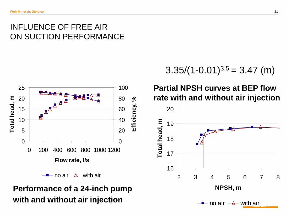
INFLUENCE OF FREE AIR ON SUCTION PERFORMANCE
0
5
10
15
20
25
0 200 400 600 800 1000 1200
Flow rate, l/s
Tota
l hea
d, m
0
20
40
60
80
100
Effic
ienc
y, %
no air with air16
17
18
19
20
2 3 4 5 6 7 8
NPSH, m
Tota
l hea
d, m
no air with air
Performance of a 24-inch pump with and without air injection
Partial NPSH curves at BEP flow rate with and without air injection
3.35/(1-0.01)3.5 = 3.47 (m)

22 Weir Minerals Division
Addition of free air to pumped slurry should affect NPSHR quite substantially.
The data for air injection when pumping water without solids suggest that the NPSHR corresponding to 3% head drop will increase.
When the approximate air content at pump inlet is known, this increase can be roughly estimated.
23 Weir Minerals Division
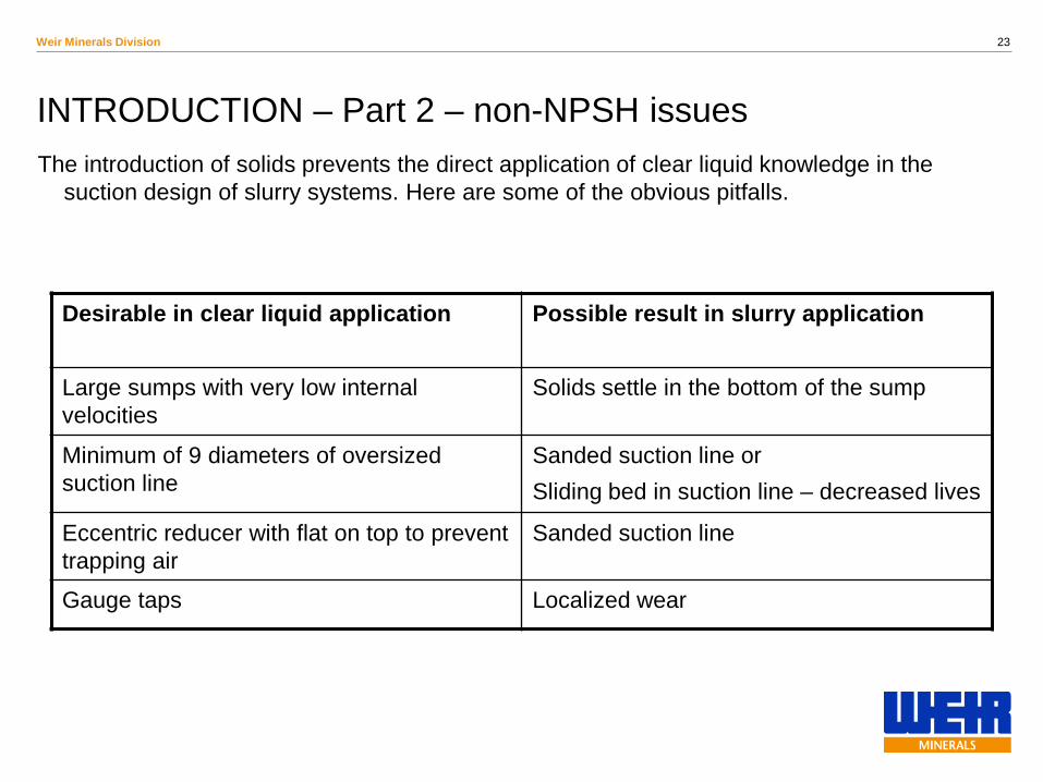
The introduction of solids prevents the direct application of clear liquid knowledge in the suction design of slurry systems. Here are some of the obvious pitfalls.
INTRODUCTION – Part 2 – non-NPSH issues
Desirable in clear liquid application Possible result in slurry application
Large sumps with very low internal velocities
Solids settle in the bottom of the sump
Minimum of 9 diameters of oversized suction line
Sanded suction line or Sliding bed in suction line – decreased lives
Eccentric reducer with flat on top to prevent trapping air
Sanded suction line
Gauge taps Localized wear

24 Weir Minerals Division
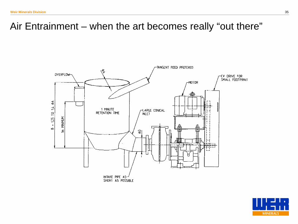
Slurry pump hoppers or sumps should be designed to allow for the expected flow rate variation without overflowing or running at low levels that allow air to enter the pumps via vortices. In general the pump hopper should be designed to minimise settling of the solid particles in the hopper.
The minimum sump level should not be less that 2 intake pipe diameters above the top of the intake pipe to the pump. The suction pipe from the hopper to the pump should be inclined at an angle of 30 degrees (if practical) to prevent air from accumulating in the suction pipe.
The slurry should be introduced to the pump hopper in such a way as to minimise the amount of air introduced to the slurry in the pump hopper. This can be achieved by the use of baffles, extending the slurry inlet pipe below the normal operating level in the sump or directing the slurry inlet away from the entrance to the pump intake pipe.
When using an operating / standby arrangement for Mill Pumps it is advisable to use a double hopper arrangement to allow the standby pump / hopper combination to be completely drained on shutdown to prevent solids build up in the pump, hopper or discharge pipe work
Suction Sump Hopper Designs – Warman Pumping Manual

25 Weir Minerals Division
Guidelines for Sump Design – Where Science Needs Art
Hopper must be both large enough to provide adequate reserve, provide surge capacity, allow air to be released at surface, while simultaneously preventing sanding.
Make as tall as practical NPSHA Surge capacity Free power
Slope bottom 30°to prevent collection of solids
Ideally have pipe come off at 30°to allow air in suction pipe to come back into sump
Large enough surface area to promote release of air
Locate sump supply pipe to eliminate air entrainment as slurry enters sump

26 Weir Minerals Division
Prior Envirotech Pumpsystems experience
Suction Sump Design for Mill Circuits

27 Weir Minerals Division
Mill Pump Sumps
To protect pumps from damage by large tramp material or impact from mill balls a suction strainer can be incorporated into the tank. Aperture sizes in the strainer must be adequate to prevent blocking and to minimise intake head loss. (Refer photos below). This method is particularly recommended if there is no trommel screen or vibrating screen on the discharge of a mill.

28 Weir Minerals Division
Guidelines for Suction Pipe Design – Where Science Needs Art
Must review minimum transport velocities at all anticipated flow rates. Suction pipe is usually the largest diameter so presents a likely location for sanding. Most often the pump is considered the determining factor for minimum capacity. But most often, sanding of lines is the real problem.
As velocity decreases, the flow regime moved from heterogeneous suspension (no deposition), through sliding bed, through stationary bed, ending up with blocked pipe.
Partially self-limiting as effective area decreases forcing velocity upwards.
Sliding beds usually cause decreased pump component life.

29 Weir Minerals Division
Suction Pipe Reducers
Which is correct? Pump is on the left.
Flat on top
Flat on bottom
Can’t decide
30 Weir Minerals Division
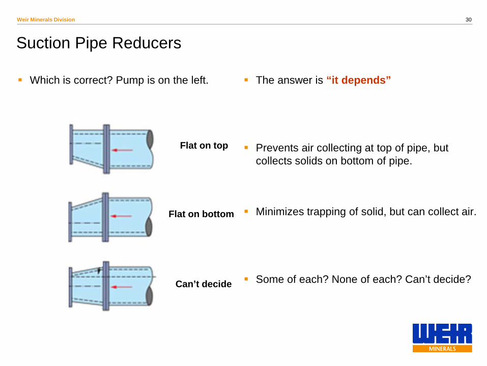
Suction Pipe Reducers
Which is correct? Pump is on the left.
The answer is “it depends”
Prevents air collecting at top of pipe, but collects solids on bottom of pipe.
Minimizes trapping of solid, but can collect air.
Some of each? None of each? Can’t decide?
Flat on top
Flat on bottom
Can’t decide

31 Weir Minerals Division
Mill Pump Sumps – added comments
• The minimum slurry level in the sump should not be less that 2 intake pipe diameters above the top of the intake pipe to the pump, more may be required in highly agitated sumps. The normal slurry level should be at least 6 to 7 times the diameter of the pump intake pipe.
• Sump make-up/flush water should be added below the slurry level in the sump and used to control the overall sump level.
• It is recommended to install an inclined baffle or grizzly screen with a cleanout access in the sump.

32 Weir Minerals Division
Mill Pump Sumps – Comments from Ricardo Abarca • The solution, we found best, is to take both suction pipes inside the tank, close enough one to the other, so the flow movement of the operating pump keeps clean the entrance of the pump that is on a standby.
33 Weir Minerals Division
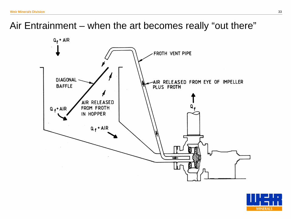
Air Entrainment – when the art becomes really “out there”

34 Weir Minerals Division
Air Entrainment – when the art becomes really “out there”
35 Weir Minerals Division
Air Entrainment – when the art becomes really “out there”
36 Weir Minerals Division
Air Entrainment
This discussion is aimed at sump design, not pump design. That is another Arts and Science project. Papers have been presented on froth pump design at this symposium in recent years.
One of the improvements to this situation that will benefit all pump types is having a very deep sump. This can only be obtained if the liquid supply is high in the plant. The added suction pressure reduces the bubble size. For example, consider suction head equal to zero gauge (at pump centreline) and compare to the same aerated stream at 1 atmosphere gauge suction pressure, the bubble is half the size. Another major benefit of this higher suction head is the free power that I mentioned
earlier. If my total head is 100 m, I require a certain amount of power for a given flow rate and SG. If I can add 10 m to my suction tank, my total head goes to 90 m, and I get an immediate 10% reduction in power consumption, regardless of pump efficiency.

37 Weir Minerals Division
Another Unusual Suction Condition
DIFFERENTIAL COLUMN HEAD LOSS
In a dredging application, we are picking up a slurry that has an SG higher than water, but the surrounding liquid column is essentially water at 1.0 SG. This will not support as high column of slurry as it would water, so NPSHA and total head need to be adjusted.
38 Weir Minerals Division
Conclusions
The first part of the presentation is science. Much has been published on NPSH for clear liquids, but very little specifically for slurry. If you want to investigate this topic in more depth, see Dr. Roudnev’s paper “Slurry pump suction performance considerations”, ©BHR Group, 2004 Hydrotransport 14. The bibliography in that paper will lead you to 15 others.
The second part of the presentation is a mixture of arts and science. There are too many variables in the nature of slurry to allow it to be reduced (or elevated) to science.
From the pump manufacturers’ points of view, the answer is simple. Give us properly designed pump boxes that are very tall, with high suction levels. The reality is that it can be very expensive to do this in large installations.
But it is much more expensive to fix an installation than didn’t consider these requirements during the design stages.
Weir is working towards collecting field data and publishing a paper with more practical recommendations on sump design. Hopefully, it will be published next year.

39 Weir Minerals Division
Caption – if desired
Questions and Comments