welcome to workshop 88’s arduino 301: control the world! please have your arduino, ide, and...
TRANSCRIPT

Welcome to Workshop 88’s
Arduino 301:Control the World!
Please have your Arduino, IDE,and breadboard fired up and ready to go.
ver 1.0 2/2/14

What we’re going to cover
• Arduino pins: What you can connect directly• For more muscle: Relays, Transistors• Solid state relays and 120VAC control• Movers: Servos, DC motors, Solenoids, Steppers• Bonus demo: BLDC motor intro
Some of this is Arduino, some basic electronics.

Please Introduce Yourself!
• Name, job, school etc• Why you’re here• Programming in general, and with
Arduino in particular• Electronics experience: Digital?
Analog? AC house wiring?• Hobby stuff: Robots? RC vehicles?

What we’re going to cover
• Arduino pins: What you can connect directly• For more muscle: Relays, Transistors• Solid state relays and 120VAC control• Movers: Servos, DC motors, Solenoids, Steppers
Some of this is Arduino, some basic electronics.

Direct connect
• Arduino I/O pin hardware capabilities

Direct connect
• Arduino I/O pin hardware capabilitiesAtmel AVR processor
Direct connect
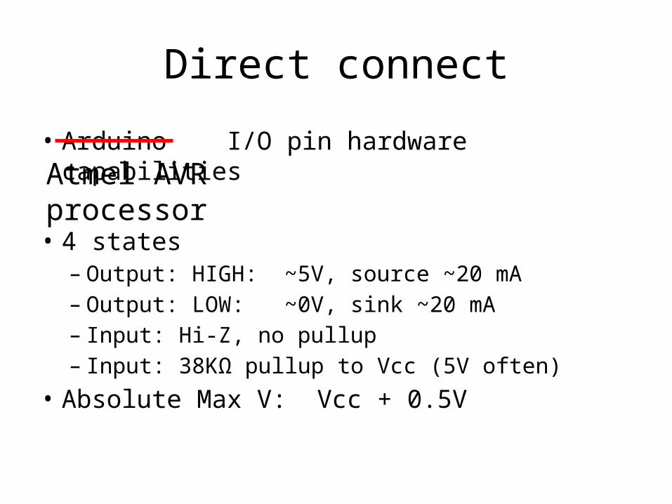
• Arduino I/O pin hardware capabilities
• 4 states– Output: HIGH: ~5V, source ~20 mA– Output: LOW: ~0V, sink ~20 mA– Input: Hi-Z, no pullup– Input: 38KΩ pullup to Vcc (5V often)
• Absolute Max V: Vcc + 0.5V
Atmel AVR processor
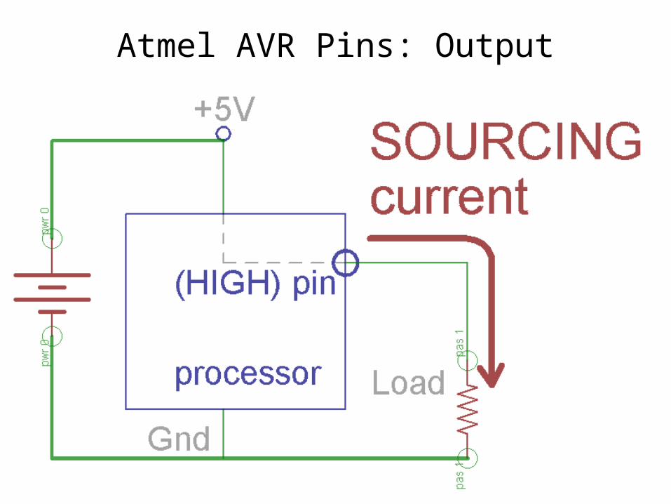
Atmel AVR Pins: Output
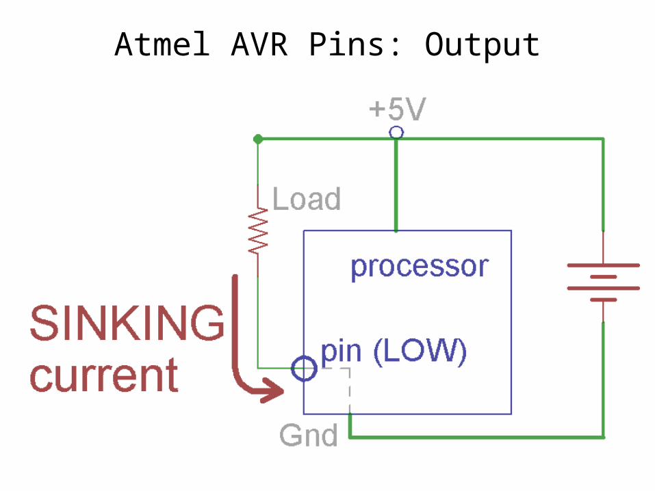
Atmel AVR Pins: Output

Atmel AVR Pins: Input - Normal
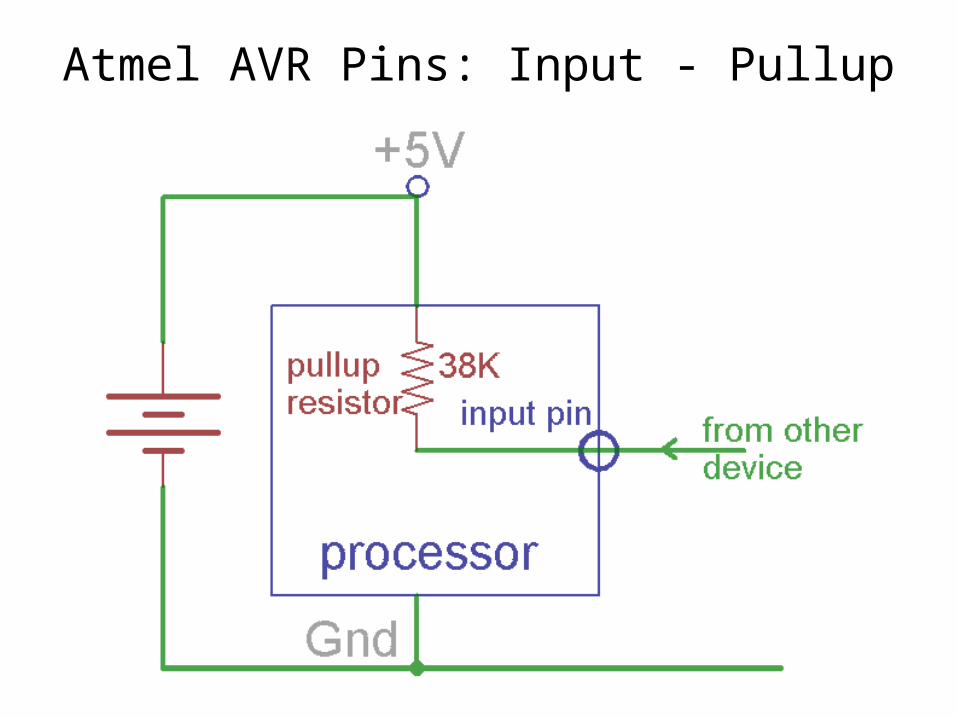
Atmel AVR Pins: Input - Pullup

Atmel AVR Pins: Input - Button

How do you know the details?
Look at the datasheet!

Direct connect (Output!)
• LED (with resistor!)• Some input expecting a “logic level”• Opto isolator (looks just like an LED!)

Direct connect: PWM
Digital output are either ON or OFF but a computer can turn them ON and OFF really fast.
If fast enough you get an effect in between ON and OFF.
Works great for LED brightness control.
Direct connect: PWM
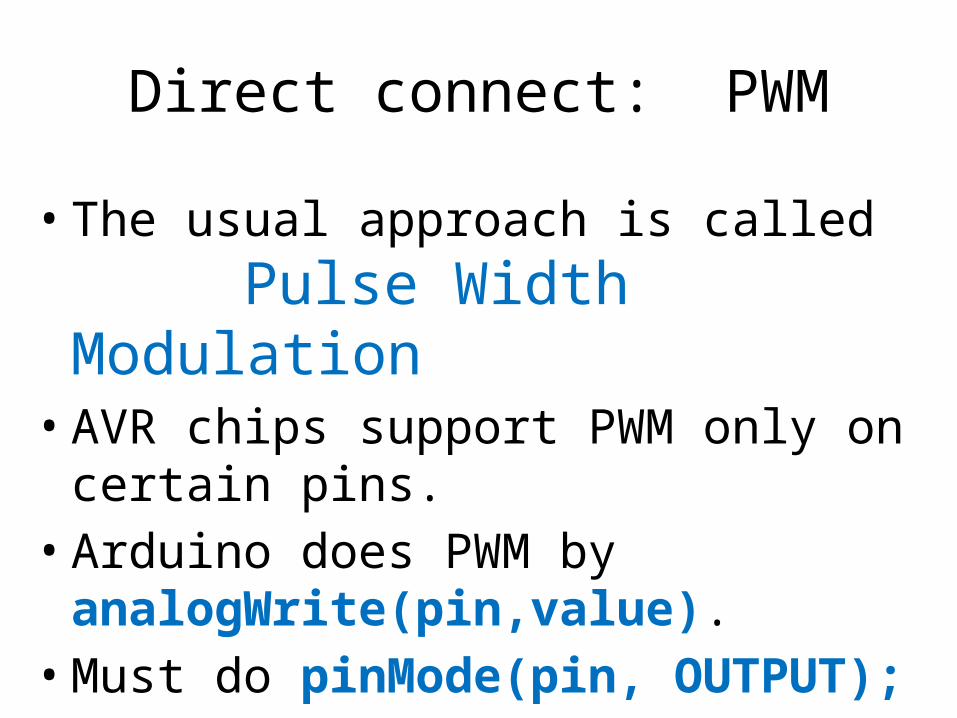
• The usual approach is called Pulse Width Modulation
• AVR chips support PWM only on certain pins.• Arduino does PWM by
analogWrite(pin,value).• Must do pinMode(pin, OUTPUT);• analogWrite() accepts 8-bit values (0-255).

Direct connect: PWM
Direct connect: PWM
(demo with scope)

Direct connect: PWM LED lab
Run up 2 LEDs, fading up/down, 180° out of phase.

Direct connect: PWM and LEDs
PWM is especially good for dimming LEDs since brightness is directly related to current.
Varying voltage to an LED+resistor doesn’t work well at low levels.

Direct connect: PWM and LEDs
(demo LED with PWM v varied voltage using scope meters)

Direct connect: logic level input
• “TTL” standard• Servos (we’ll cover those later)• Serial communication• Any device with I2C or SPI interface

Direct connect: logic level input

Direct connect: opto isolator

What we’re going to cover
• Arduino pins: What you can connect directly• For more muscle: Relays, Transistors• Solid state relays and 120VAC control• Movers: Servos, DC motors, Solenoids, Steppers• Bonus demo: BLDC motor intro
This is all basic electronics.

More muscle: Relays & Transistors
•Let us control higher CURRENT•Let us control higher VOLTAGE•Sometimes provide ISOLATION

More muscle: Relays
Classic open-frame relay

More muscle : Relays
What you’re likely to use: a reed relay

More muscle : Relays
Inside a reed relay

Relays: Snubber!
• Snubber, clamp, flyback, suppressor, free-wheeling, catch diode
• Do some kind of demo

Snubber/Freewheel/Clamp Diode

More muscle : Transistors
We can use transistors as electronically controlled switches.
(Sort of like a relay, but often better.)

More muscle : Transistors
•Lots of kinds of transistors•We’ll use two:•Common bipolar•Metal Oxide Field Effect (MOSFET)

More muscle : Transistors: Bipolar
This is the most common type of bipolar transistor, and is the one we’ll use here.

More muscle : Transistors: Bipolar
Think of it as this:
In general, transistors can be considered amplifiers, but

More muscle : Transistors: Bipolar

More muscle : Transistors: Bipolar
Point iN Place

More muscle : Transistors

More muscle : Transistors
Switching terms:
“HIGHSIDE”
“LOWSIDE”

More muscle : Transistors: Bipolar

More muscle : Transistors: Bipolar
How?

More muscle : Transistors: Bipolar
Inject small currentinto BASEto EMITTERto turntransistor ON
Maincurrentflow

More muscle : Transistors: Bipolar

More muscle : Transistors: Bipolar

More muscle : Transistor Lab 1
2N2222

More muscle : Transistors: Bipolar
What part numbers?–NPN: 2N2222(A), 2N3904–PNP: 2N2907, 2N3906
What’s important?–Max collector voltage–Max collector current

More muscle : Transistors: Bipolar

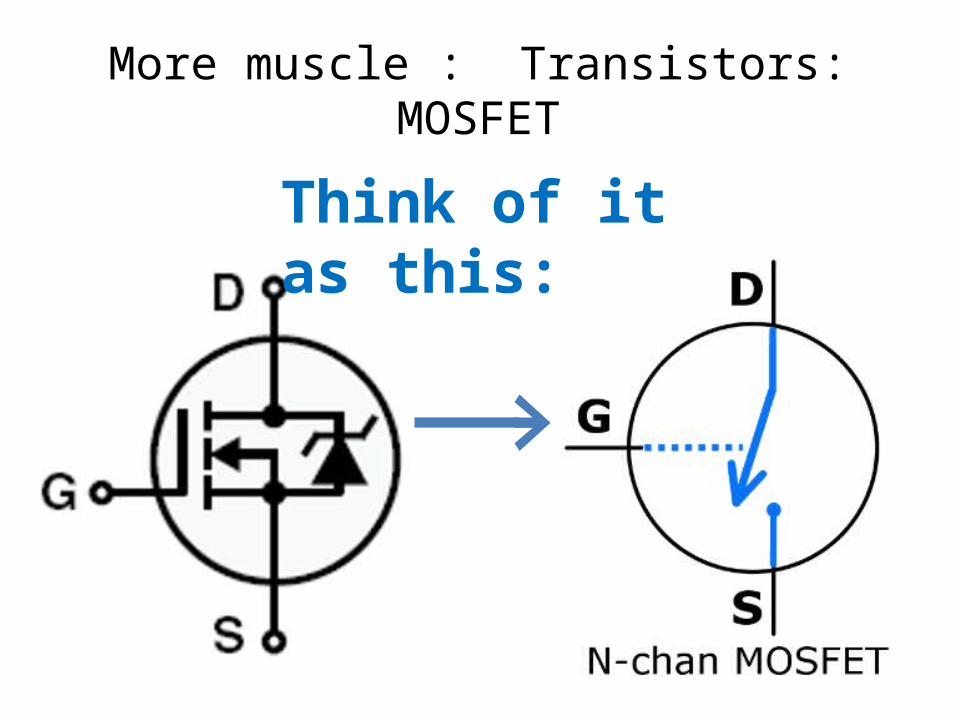
More muscle : Transistors: MOSFET
These are great!• Voltage controlled• VERY low ON
resistance
Insulated Gate!
More muscle : Transistors: MOSFET
Think of it as this:

More muscle : Transistors: MOSFET

More muscle : Transistors: MOSFET

More muscle : Transistors: MOSFET
How?

More muscle : Transistors: MOSFET
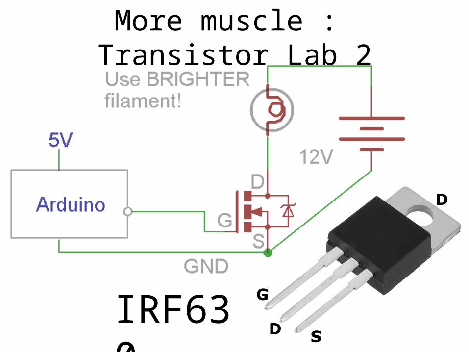
More muscle : Transistor Lab 2
IRF630

What we’re going to cover
• Arduino pins: What you can connect directly• For more muscle: Relays, Transistors• Solid state relays and 120VAC control• Movers: Servos, DC motors, Solenoids, Steppers• Bonus demo: BLDC motor intro
This is all basic electronics.

Optos: Solid State Relay
PWM does NOT work with these!

Optos: Solid State Relay

Optos: SSR Lab
Warning:We’re not in Kansas any more, Toto. In
addition to 5V toys that couldn’t hurt you if they tried, there’s exposed 120 volts AC here that can kill you.
Be careful out there.

Optos: SSR Lab
• Set up a “blink” sketch on your Arduino• Use I/O pin of your choice• Wire the AC side of the SSR in series with AC
plug and socket. Have your setup checked BEFORE you plug it in!
• Wire the LED side of the SSR to your Arduino.• Plug in and try it out!
What we’re going to cover
• Arduino pins: What you can connect directly• For more muscle: Relays, Transistors• Solid state relays and 120VAC control• Movers: Servos, DC motors, Solenoids, Steppers• Bonus demo: BLDC motor intro
Some of this is Arduino, some basic electronics.

Movers
We’ll talk about these:• Servos• DC motors• Solenoids• Stepper motors• Brushless DC motors

Movers: Servos

Movers: Servos
• Use feedback to control position• Hobby/RC servos use logic level pulse input• Continuous rotation servos are like motors• Other kinds exist

Movers: Servo feedback

Movers: Servo input

Movers: Servo libraryArduino controls PWM specifically to drive servos with the SERVO library. Initialize like this:
#include <Servo.h>
Servo fred; // “myservo” would be better!#define SERVOPIN 9
void setup() fred.attach(SERVOPIN);
void loop()

Movers: Servo library
Telling servo where to go with Servo.write():
void loop()
fred.write(90); // go to midpoint delay(1000);
fred.write(0); // go to one end of travel delay(1000);
fred.write(180); // go to OTHER end of travel delay(1000);
//end loop()

Movers: Servo library
Other functions in Servo library:
• Specify pulse width for 0, 180 in microseconds fred.attach(pin, min, max); // default 544,2400
• Read back latest position written with servo.write() int angle = fred.read();
• Specify pulse width in microseconds fred.writeMicroseconds(value);

Movers: Servo Lab
• Load the Sweep example• Do NOT use the default pin• Modify so that it:– Sweeps twice as fast–Pauses at each end of each sweep
• Predict what you’ll see with an LED on the servo input pin (and check it out!)

Movers: Servo: RC transmitter

Movers: Servo: RC receiver
Movers: Continuous rotation servos

Movers: DC motors
• Always only 2 wires• Reverse by reversing polarity
Movers: DC motors
Regular “brushed” motors controlled by:• Relays (old school!)• FETs• Use PWM for speed control• “H-bridges” for reversing direction
Movers: DC motors
Try this paper lab:
How can you arrange some switches to connect a battery
and a DC motor so you can control the motor direction?

Movers: H-bridge

Movers: H-bridge

Movers: H-bridge
A B

Movers: H-bridge
Movers: H-bridge Lab
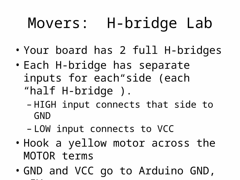
• Your board has 2 full H-bridges• Each H-bridge has separate inputs for each
side (each “half H-bridge”). – HIGH input connects that side to GND– LOW input connects to VCC
• Hook a yellow motor across the MOTOR terms• GND and VCC go to Arduino GND, +5V• Inputs go to 2 Arduino output pins.
Movers: H-bridge Lab
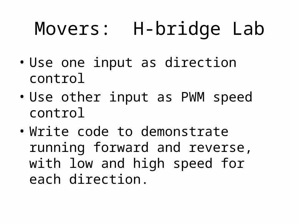
• Use one input as direction control• Use other input as PWM speed control• Write code to demonstrate running forward
and reverse, with low and high speed for each direction.

Movers: Robot Lab
1. Make robot.2. Write code to:– Drive forward in a gentle right
hand curve for ~1 second, Pause– Turn 180° in place, Pause– Return to start along same path– Optionally do victory dance at end

Movers: Robot Lab
Special H-bridge cable
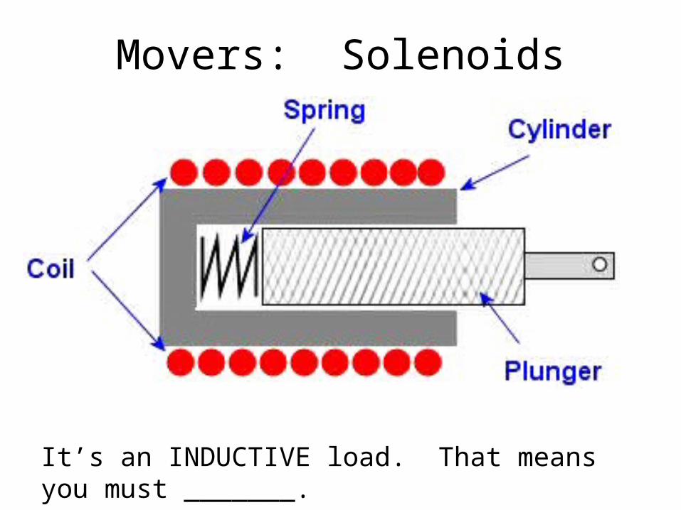
Movers: Solenoids
It’s an INDUCTIVE load. That means you must _______.

Movers: Steppers
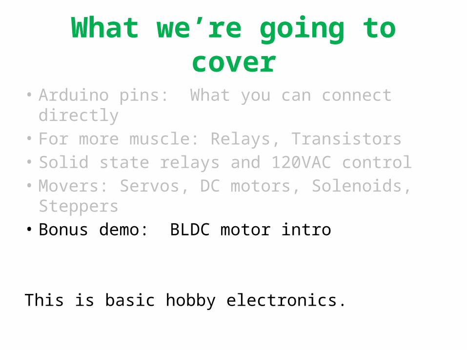
What we’re going to cover
• Arduino pins: What you can connect directly• For more muscle: Relays, Transistors• Solid state relays and 120VAC control• Movers: Servos, DC motors, Solenoids, Steppers• Bonus demo: BLDC motor intro
This is basic hobby electronics.

Movers: BLDC motors
“Brushless DC” motors:• ARE brushless• ARE NOT DC. They’re 3 phase AC
motors!• Must use special 3 phase inverter, often
called an Electronic Speed Control to run from DC supply
• Are often very light and efficient

Movers: BLDC motors: Quadcopter

Movers: BLDC motors
The interesting part is the ESC• Has an embedded processor• Uses PWM on the 3 phase AC for
speed control• Speed control input is servo pulse train• Hobby ESCs often provide 5V to run
the RC receiver. That’s called Battery Eliminator Circuit.

Movers: Servo: RC receiver

Movers: ESC/BEC
ESC has to connect to receiver anyway (for throttle info), so it provides power to the receiver on the same cable.

Movers: BLDC demo
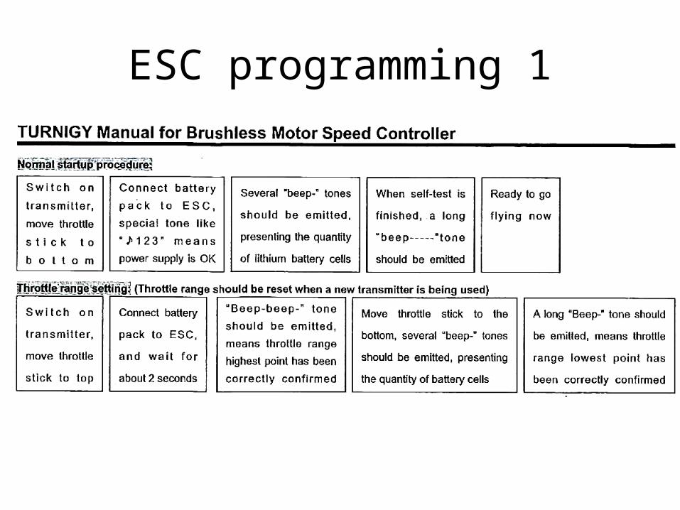
ESC programming 1

ESC
prog
ram
min
g 2

Thanks for coming!