weld package dual wire 2 - sks: welding · 12 6 4 9 this brochure contains information about the...
TRANSCRIPT

Solutions for: ABB • FANUC • KUKA • YASKAWA/MOTOMAN
Dual Wire 2.0 Weld Package: DCT power source • Weld process controller • Robot interface • Wire feeder• Wire Guidance • Cable bundle • Control cable •
Torch system • Torch necks • Consumables
Document no.: DOC-0114EN | Revision: SKSde.06DEZ19.ms.bp.v2.0.0
Weld Package dual Wire 2.0For high welding speed and high deposition rate

12
6
4
9
This brochure contains information about the SKS Weld Package, the torch system Dual Wire 2.0, as well as consumables and spare parts. There are various features of the welding machine components and torch systems available depending on the robot system and the welding task. The Dual Wire 2.0 Weld Package can be used with common industrial robots, such as ABB, FANUC, KUKA and YASKAWA/MOTOMAN.
SKS Weld Package: System design
DCT power source
Robot interface
Wire feeder
Wire guidance
Cable bundle
Torch system Dual Wire 2.0
Ground cable
Torch necks/Consumables/Reamer blades/Checking fixtures
Control cable
Water cooling
TCP dimensions/eReam
Weld process controller + Software
1
5
3
7
10
2
6
9
4
8
11
12
For installations with outer cable dress.
55
7
8
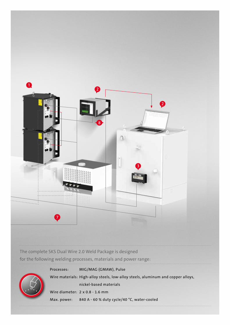
Processes: MIG/MAG (GMAW), Pulse
Wire materials: High-alloy steels, low-alloy steels, aluminum and copper alloys,
nickel-based materials
Wire diameter: 2 x 0.8 - 1.6 mm
Max. power: 840 A - 60 % duty cycle/40 °C, water-cooled
The complete SKS Dual Wire 2.0 Weld Package is designedfor the following welding processes, materials and power range:
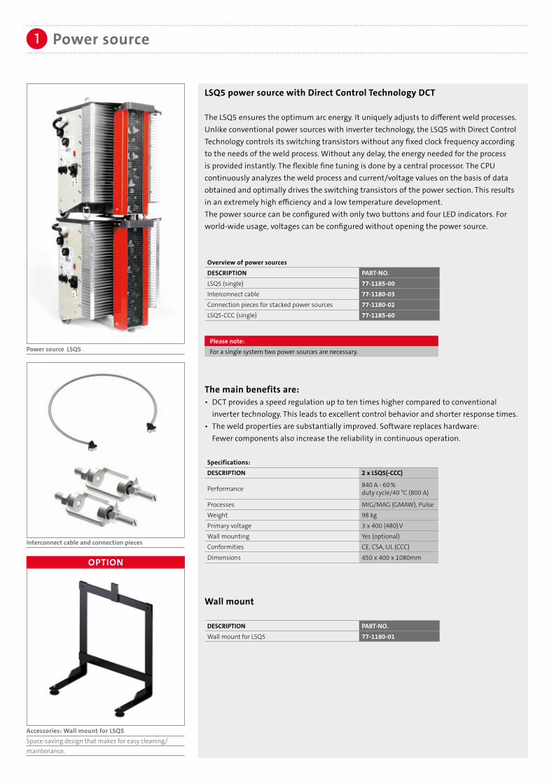
Power source LSQ5
Interconnect cable and connection pieces
Power source
LSQ5 power source with Direct Control Technology DCT
The LSQ5 ensures the optimum arc energy. It uniquely adjusts to different weld processes. Unlike conventional power sources with inverter technology, the LSQ5 with Direct Control Technology controls its switching transistors without any fixed clock frequency according to the needs of the weld process. Without any delay, the energy needed for the process is provided instantly. The flexible fine tuning is done by a central processor. The CPU continuously analyzes the weld process and current/voltage values on the basis of data obtained and optimally drives the switching transistors of the power section. This results in an extremely high efficiency and a low temperature development. The power source can be configured with only two buttons and four LED indicators. For world-wide usage, voltages can be configured without opening the power source.
Overview of power sourcesDESCRIPTION PART-NO.LSQ5 (single) 77-1185-00Interconnect cable 77-1180-03Connection pieces for stacked power sources 77-1180-02LSQ5-CCC (single) 77-1185-60
Please note:For a single system two power sources are necessary.
The main benefits are: • DCT provides a speed regulation up to ten times higher compared to conventional inverter technology. This leads to excellent control behavior and shorter response times.• The weld properties are substantially improved. Software replaces hardware: Fewer components also increase the reliability in continuous operation.
Specifications:DESCRIPTION 2 x LSQ5(-CCC)
Performance 840 A - 60% duty cycle/40 °C (800 A)
Processes MIG/MAG (GMAW), PulseWeight 98 kgPrimary voltage 3 x 400 (480)VWall mounting Yes (optional)Conformities CE, CSA, UL (CCC)
Dimensions 450 x 400 x 1080mm
Wall mount DESCRIPTION PART-NO.Wall mount for LSQ5 77-1180-01
OPTION
Accessories: Wall mount for LSQ5Space-saving design that makes for easy cleaning/maintenance.

Weld process controller2
Innovative Control Concepts with Touch Screen.With the new Q84r and the compact Q84s up to four weld machines can be controlled centrally.
The new Q84r and Q84s are equipped with a touch screen, an innovative usability concept and an advanced visualization technology for much easier operating. The user interfaces have the look and feel of the Q8Tool4 software. Individual weld process controllers are in card slots in the Q84r/s. This new weld process controller concept can host up to four weld process controller cards. Each card independently controls a weld machine. As an alternative to the Q84r/s weld process controllers, the Q80 has been developed to control a single weld machine.
Weld process controller Q84r Weld process controller Q80Weld process controller Q84s

Weld process controller2
Controlling up to four weld machines at the same time
3
4 3 2 1
42
1
Please note:The Q84r/s can be equipped with up to four weldprocess controller cards.
Weld process controller Q84r
Weld process controller Q84s
Weld process controller Q84r/s
The universal weld process controllers Q84r and Q84s calculate the optimal parameters for each welding process. Only basic data such as material, wire type, wire feed speed and type of gas must be entered. The Q84r is equipped with a 10" touch screen, the space-saving Q84s with a 7" touch screen. For wall mounting the display of the Q84s can be rotated by an angle of 180°.• Processes/features: MIG/MAG (GMAW), I-Pulse, U-Pulse, KF-Pulse, Synchroweld, RWDE, NWDE• Programs: 992 (x4)• General functions: Display and saving of readings, alarms• Monitoring functions: Weld current monitoring, auto compensation, arc and ignition monitoring, motor current, gas and water monitoring• Easy to network via Ethernet: Traceability• Ports: RJ45-Ethernet, SPW-Bus, SD card slot• Remote Control/Administration: Q8Tool, VNC client
Overview weld process controllerDESCRIPTION PART-NO. (Q84s) PART-NO. (Q84r)Q84r/s with one weld card 77-7410-00 77-7310-00Q84r/s with two weld cards 77-7420-00 77-7320-00Q84r/s with three weld cards 77-7430-00 77-7330-00Q84r/s with four weld cards 77-7440-00 77-7340-00
Overview Q84r/s mounting kits DESCRIPTION PART-NO.Bracket for Q84r for mounting onto power source LSQ5 77-7240-01Bracket for Q84s for mounting onto power source LSQ5 77-7240-06Bracket for Q84r for wall mounting 77-7240-02Bracket for Q84r mounting in the robot cabinet 77-7240-05
Overview Q84r/s replacement parts and accessoriesDESCRIPTION PART-NO.Touchpen for Q80 / Q84r/s weld process controller (replacement part) 77-7240-03Connection cable for Q84r/s 5m with open end for external power supply (option) 77-3305-00Plug for external power supply of Q84r/s (replacement part) 77-7240-96SD card for Q80 / Q84r/s weld process controller (replacement part) 91-8-6USB adapter for SD cards for Q80 / Q84r/s weld process controller 91-8-1

Weld process controller2
ALTERNATIVE
Weld process controller Q80 front view
Weld process controller Q80 back view
Q8Tool software
The Q8Tool software provides accurate and comprehensive process monitoring. The user can store weld parameters for documentation on a PC and/or administrate them. It offers basic functions such as reading, modifying and documenting of weld parameters. Additionally, new weld parameters can be created and transferred to the universal weld process controllers. The weld data is portable and the installation of further control units on new equipment is easy. Also, the software allows reading and exporting of measurements and alarms. Graphical and numerical recording of measures helps defining and optimizing parameters for new parts. Users have a powerful tool for analyzing and documenting their weld results.
Network
The weld process controller units can easily be networked via Ethernet ports: Time savings through centralized administration of all controllers within the corporate network. There is a central backup of all welding parameters, management of user rights and access, process monitoring up to traceability. The Q8Tool software is provided free of charge with the weld process controller. No additional hardware or software is required.
Software/IT2a
Weld process controller Q80 The Q80 is the alternative to the Q84r/s. It has the same functionality/features as a singleweld card of the Q84r/s - optimized for a single weld machine. With the universal Q80 all parameters and values needed for the weld task can be optimally calculated.• Processes/features/general functions see Q84r/s• Easy to network via Ethernet: up to traceability• Ports: RJ45-Ethernet, SPW-Bus, SD card slot• Wall mounting capability • Remote Control / Administration: Q8Tool
Overview weld process controllerDESCRIPTION PART-NO.Q80 77-7260-00
Overview Q80 mounting kitsDESCRIPTION PART-NO.Bracket for mounting onto power source LSQ5 77-7240-06
Overview Q80 replacement parts and accessoriesDESCRIPTION PART-NO.Touchpen for Q80 / Q84r/s weld process controller (replacement part) 77-7240-03SD card for Q80 / Q84r/s weld process controller (replacement part) 91-8-6USB adapter for SD cards for Q80 / Q84r/s weld process controller 91-8-1

Robot interface3
Perfect integration.Interfacing all industrial robot types.
With the universal interface solution, weld process controllers can be connected with all industrial robot types. Users basically have two options for connecting robots with weld process controllers: The connection can be realized with the interface UNI 5 or by integrating into a given field bus environment with a field bus solution.
Robot controllers or overall system controllers (e.g. PLC) use digital or analog signals to communicate with the weld process controller. The interface UNI 5 translates these signals for the welding machine. With just one interface, a variety of digital encodings and analog levels can be processed. The interface UNI 5 comes with a preconfigured connection kit for easy installation.
Field bus systems exchange signals via serial communication. The field bus master, usually the robot controller or overall system controller, bundles and processes the signals of the connected field bus, including the welding machine. Standard field bus systems are e.g., Interbus-S, Profibus DP or DeviceNet. The field bus interface FB5 translates the field bus signals for the welding machine using a standardized protocol. It makes no difference which type of field bus system is used. The signals are always at the same place on the field bus. This makes the preparation of the robot or system controller much easier.
Standard application Field bus application
A B

Robot interface UNI 5
The interface connects the welding equipment with all industrial robot types. With its high degree of standardization, the UNI 5 is the perfect choice for connecting the weld process controller (e.g. Q80) with an industrial robot. The UNI 5 comes preprogrammed and configured for different robot types. Configuration to a particular robot type is handled easily by programming the interface with two buttons for the given robot type.
Overview of robot interfacesDESCRIPTION PART-NO.For robot type-ABBUNI 5A for IRC5 77-8011-08
For robot type-FANUCUNI 5A for RJ3iC 77-8001-84
For robot type-KUKAUNI 5A for KR C2 77-8011-08
For robot type-YASKAWA/MOTOMAN
UNI 5C (Synchroweld over RS232) for NX 100 / DX 100 / DX 200 77-8013-00
Robot interface3
ALTERNATIVE
A
B
Synchroweld unites the weld system and robot by a communication protocol (RWDE). This technology allows the weld system to get the actual robot speed and automatically adjusts the weld parame-ters accordingly. The result is a constant energy per unit length. At the same time, the programming effort can be signifi-cantly reduced.
OPTION
Please note:
Further information on Synchroweld with ABB, Fanuc, KUKA, Yaskawa/Motoman can be found in our Synchroweld brochure.
Field bus application
Various field bus types are supported (e.g. Profibus DP, DeviceNet). The field bus interface has drilled bore holes for flexible mounting within the weld cell. Two additional mounting kits provide easy installation at the power source or into the cabinet. Additionally, external power can be connected to the interface. More details on solutions for the specific field bus types are available on request.
Overview FB5 interfacesDESCRIPTION PART-NO.
Interbus-S (copper line) 77-3-1
Profibus DP 77-3-2DeviceNet 77-3-3EtherCAT 77-3-4Profinet IRT (copper line) 77-3-5Profinet IRT (LWL 2 ports) 77-3-6Interbus-S (LWL FSMA) 77-3-7Ethernet/IP 77-3-8
Cabinet mountingDESCRIPTION PART-NO.Mounting kit for cabinet 77-1182-02Control cable with bracket 77-3102-02
Power source mountingDESCRIPTION PART-NO.Mounting kit for power source 77-1182-03
Optional power supply (24V)DESCRIPTION PART-NO.Connection cable 2.0 m (with open end) 77-1182-04

Smaller and with less weight accompanied by improved efficiency over conventional wire feeders the PF5 goes along with the steady development of arc welding robots.
Power Feeder PF5
Modern motor, gear and control technology provide a strong performance and highest pos-sible precision. The robust plastic housing is electrically insulated. As a "lightweight" the PF5 is the perfect choice for the new generation of robots with inner cable dress. The industrial proven Power Feeder PF5 is available with an additional monitoring func-tionality: an integrated gas-flow sensor. The weld process controller displays the gas flow values, and can also be triggered to an alarm, in case of a non-defined gas flow rate.
Wire feeder4
Strong, lightweight and precise.The PF5 wire feeder.
ALTERNATIVE
PF5 L/R with integrated gas flow sensor
Overview PF5DESCRIPTION PART-NO.PF5 L 10-2-8PF5 R 10-2-4PF5 L with integrated gas flow sensor 10-2-108PF5 R with integrated gas flow sensor 10-2-104
Technical dataWeight 3,8 kgMotor 70WWire feeding speed 2,5 - 25 m/minRoll diameter 0.8 - 1.6 mm
Shielding Gas Saver
The benefit of the shielding gas saver is its pre-regulated working pressure of 1.2 bar / 17 psi (common 4.5 bar / 65 psi). Therefore the ram pressure is reduced, i.e. there are key benefits of the shielding gas saver at ignition of the welding torch and an improved gas saving. The shielding gas saver ensures a constant gas flow during the welding task.
Shielding Gas SaverDESCRIPTION PART-NO.Shielding Gas Saver 93-62-5
4 Wire feeder
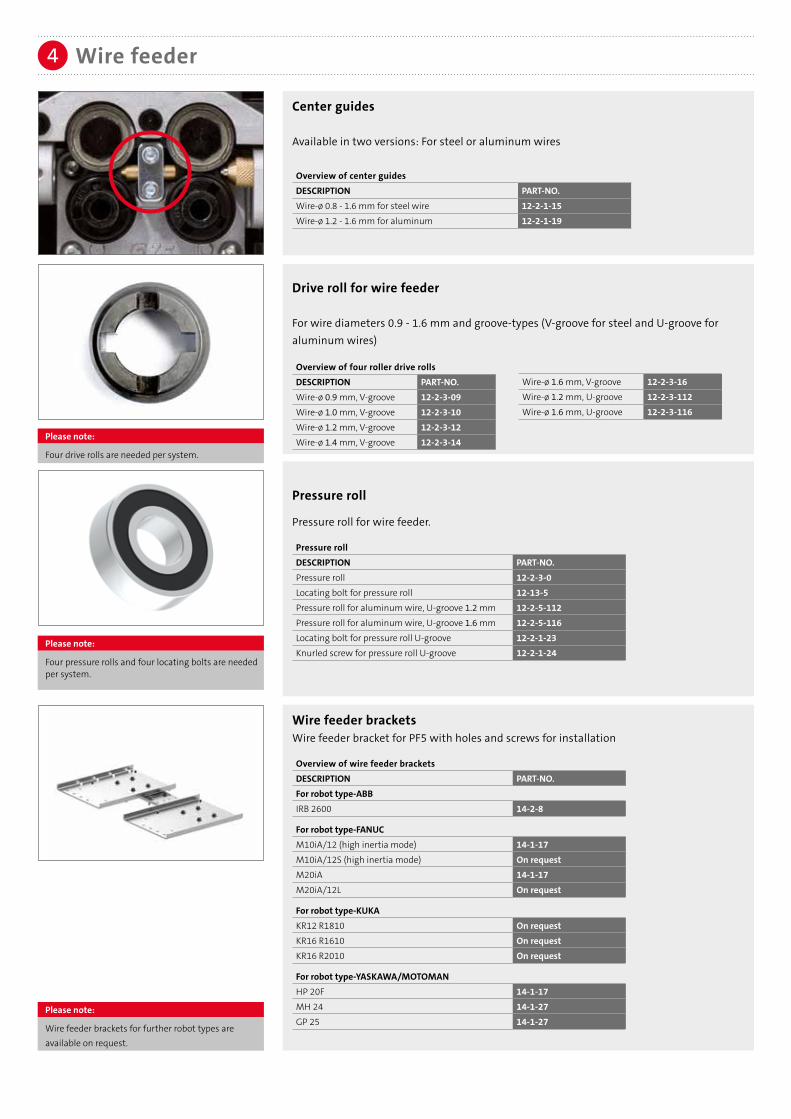
Drive roll for wire feeder
For wire diameters 0.9 - 1.6 mm and groove-types (V-groove for steel and U-groove for aluminum wires)
Center guides
Available in two versions: For steel or aluminum wires
Overview of center guidesDESCRIPTION PART-NO.Wire-ø 0.8 - 1.6 mm for steel wire 12-2-1-15Wire-ø 1.2 - 1.6 mm for aluminum 12-2-1-19
Please note:
Wire feeder brackets for further robot types are available on request.
Overview of four roller drive rollsDESCRIPTION PART-NO.Wire-ø 0.9 mm, V-groove 12-2-3-09Wire-ø 1.0 mm, V-groove 12-2-3-10Wire-ø 1.2 mm, V-groove 12-2-3-12Wire-ø 1.4 mm, V-groove 12-2-3-14
Wire-ø 1.6 mm, V-groove 12-2-3-16Wire-ø 1.2 mm, U-groove 12-2-3-112Wire-ø 1.6 mm, U-groove 12-2-3-116
Pressure roll
Pressure roll for wire feeder.
Pressure rollDESCRIPTION PART-NO.Pressure roll 12-2-3-0Locating bolt for pressure roll 12-13-5Pressure roll for aluminum wire, U-groove 1.2 mm 12-2-5-112Pressure roll for aluminum wire, U-groove 1.6 mm 12-2-5-116Locating bolt for pressure roll U-groove 12-2-1-23Knurled screw for pressure roll U-groove 12-2-1-24
Please note:
Four drive rolls are needed per system.
Please note:
Four pressure rolls and four locating bolts are needed per system.
Wire feeder bracketsWire feeder bracket for PF5 with holes and screws for installation
Overview of wire feeder bracketsDESCRIPTION PART-NO.For robot type-ABBIRB 2600 14-2-8
For robot type-FANUCM10iA/12 (high inertia mode) 14-1-17M10iA/12S (high inertia mode) On requestM20iA 14-1-17M20iA/12L On request
For robot type-KUKAKR12 R1810 On requestKR16 R1610 On requestKR16 R2010 On request
For robot type-YASKAWA/MOTOMANHP 20F 14-1-17MH 24 14-1-27GP 25 14-1-27
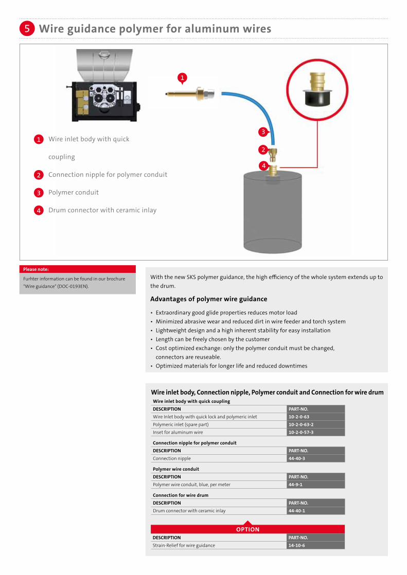
Wire guidance polymer for aluminum wires5
With the new SKS polymer guidance, the high efficiency of the whole system extends up to the drum.
Advantages of polymer wire guidance
• Extraordinary good glide properties reduces motor load• Minimized abrasive wear and reduced dirt in wire feeder and torch system• Lightweight design and a high inherent stability for easy installation• Length can be freely chosen by the customer• Cost optimized exchange: only the polymer conduit must be changed, connectors are reuseable.• Optimized materials for longer life and reduced downtimes
Wire inlet body with quick
coupling
Connection nipple for polymer conduit
Polymer conduit
Drum connector with ceramic inlay
1
4
2
3
4
2
3
Please note:
Furhter information can be found in our brochure "Wire guidance" (DOC-0193EN).
1
Wire inlet body, Connection nipple, Polymer conduit and Connection for wire drumWire inlet body with quick couplingDESCRIPTION PART-NO.Wire Inlet body with quick lock and polymeric inlet 10-2-0-63Polymeric inlet (spare part) 10-2-0-63-2Inset for aluminum wire 10-2-0-57-3
Connection nipple for polymer conduit DESCRIPTION PART-NO.Connection nipple 44-40-3
Polymer wire conduitDESCRIPTION PART-NO.Polymer wire conduit, blue, per meter 44-9-1
Connection for wire drumDESCRIPTION PART-NO.Drum connector with ceramic inlay 44-40-1
OPTIONDESCRIPTION PART-NO.Strain-Relief for wire guidance 14-10-6

Wire inlet bodies for additional systemsBeside the wire inlet body for the SKS wire guidance, inlet bodiesfor additional systems are available.
Overview of wire inlet bodies for additional systemsDESCRIPTION PART-NO.M10 with internal thread for ESAB 10-2-0-50with 9.6 mm bore hole 10-2-0-52with 13 mm bore hole 10-2-0-53with PG9 thread 10-2-0-56with 1/4” internal thread 10-2-0-60
Aluminum inlets for wire inlet bodiesDESCRIPTION PART-NO.for types 50/52/53/54/59/60/61 10-2-0-57-3for types 51/55/56 10-2-0-58-3
ALT
ERN
ATIV
E
ALTERNATIVE
With the ERC wire guidance for steel/stainless steel, the high efficiency of the whole system extends up to the drum.
Advantages• Very good inherent stability due to thick polyethylene insulating jacket• Good sliding properties• Reduced wear by using flat wire for monocoil core• Suitable for steel and stainless steel wires
Wire guidance ERCDESCRIPTION PART-NO.Wire inlet body with quick coupling 10-2-0-61Connection nipple for ERC conduit 44-70-2Polymer wire conduit ERC / per meter 44-70-1 Drum connector with ceramic inlay 44-40-1
1
4
2
3
1 2
3
2
4
Wire inlet body with quick coupling
Connection nipple for ERC conduit
Polymer wire conduit ERC
Connection for wire drum with inner ceramic inlay
Please note:
Two connection nipples are necessary.
OPTIONDESCRIPTION PART-NO.Strain Relief for wire guidance 14-10-6Strain Relief spring for wire guidance 44-70-3
Wire guidance ERC for steel and stainless steel wire materials5
6
6a
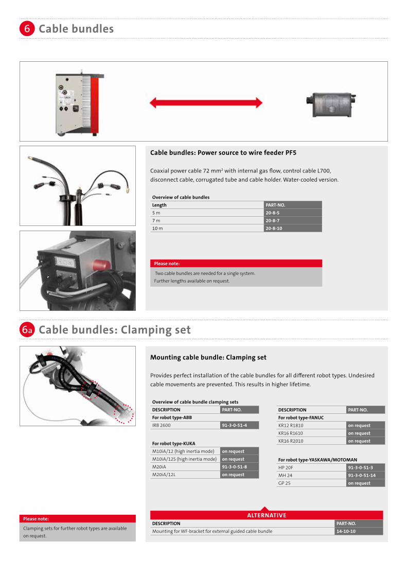
Cable bundles: Power source to wire feeder PF5
Coaxial power cable 72 mm2 with internal gas flow, control cable L700, disconnect cable, corrugated tube and cable holder. Water-cooled version.
Overview of cable bundlesLength PART-NO.5 m 20-8-57 m 20-8-710 m 20-8-10
Cable bundles
Cable bundles: Clamping set
Please note:
Clamping sets for further robot types are available on request.
Mounting cable bundle: Clamping set
Provides perfect installation of the cable bundles for all different robot types. Undesired cable movements are prevented. This results in higher lifetime.
Overview of cable bundle clamping setsDESCRIPTION PART-NO.For robot type-ABBIRB 2600 91-3-0-51-4
For robot type-KUKAM10iA/12 (high inertia mode) on requestM10iA/12S (high inertia mode) on requestM20iA 91-3-0-51-8M20iA/12L on request
DESCRIPTION PART-NO.For robot type-FANUCKR12 R1810 on requestKR16 R1610 on requestKR16 R2010 on request
For robot type-YASKAWA/MOTOMANHP 20F 91-3-0-51-3MH 24 91-3-0-51-14GP 25 on request
ALTERNATIVEDESCRIPTION PART-NO.Mounting for WF-bracket for external guided cable bundle 14-10-10
Please note:
Two cable bundles are needed for a single system.Further lengths available on request.

ALTERNATIVE
1
1
3
3
2
2
Cable bundle with separation between power source and wire feeder PF5
The moving parts of the cable bundles (next to the robot) are separated from the non-moving parts (power source). In case of maintenance work, only the moving parts have to be changed. The quick and easy replacement concept results in time and cost savings.
Dividable cable bundles
PARTS OF THE DIVIDABLE CABLE BUNDLE
Connection from power source to connection bracket
LENGTH PART-NO.5 m 20-18-57 m 20-18-710 m 20-18-10
Connection from connection bracket to wire feeder PF5
LENGTH PART-NO.3 m 20-17-35 m 20-17-57 m 20-17-7
Connection bracket
DESCRIPTION PART-NO.Connection bracket 20-17-0-3
TO POWER SOURCES TO WIRE FEEDERS
Please note:
Further lengths available on request.A single system requires two cable bundles power source/connection bracket, two connection brackets, and two cable bundles connection bracket/wire feeder.

Ground cable with 70 mm2 connector and cable plug
Cables with larger diameters are available on request
Overview of ground cablesLENGTH PART-NO. Please note:6 m 228078106 Two ground cables per10 m 228078100 system necessary.
The advantages of a system concept are revealed by its details: One standard control cable (L700) connects all system components (power source, robot interface, weld process controller and wire feeder) within the welding system. The system is expandable: Other components can be integrated at any time into an existing system. New devices are automatically detected.
Control cable: L700/SPW-bus
Standard control cable to connect the components:Weld process controller, power source, robot interface, wire feeder.
Overview of control cablesLENGTH PART-NO.0.5 m 5410310501 m 5410310012 m 5410310023 m 5410310035 m 5410310057 m 54103100710 m 54103100012 m 54103101215 m 541031015
Ground cable
Control cable
7
8
PLUG & PLAY: CONTROL CABLE L700
POWER SOURCE ROBOT INTERFACE WELD PROCESS CONTROLLER WIRE FEEDER
Please note:For the Dual Wire 2.0 system four control cables arerequired. One control cable is already included percable bundle.
Please note:
Further lengths available on request
Please note:
Further lengths available on request

Processes: MIG/MAG (GMAW), Pulse
Wire materials: High-alloy steels, low-alloy steels, aluminum and copper alloys,
nickel-based materials
Wire diameter: 2 x 0.8 - 1.6 mm
Max. power: 840 A - 60 % duty cycle/40 °C, water-cooled
The complete SKS Dual Wire 2.0 Weld Package is designedfor the following welding processes, materials and power range:
Torch system Dual Wire 2.09
High welding speed and high deposition rate.
With the torch system Dual Wire 2.0, materials thicker than 3 mm can be joined fast and easy. The bajonet quick change system is integrated into the torch, so this new torch system supports a toolless change of the torch neck; this with a guaranteed TCP of ± 0.5 mm. We integrated two separate cooling circuits to increase the operational time of the welder and achieve a better cooling effect with this separation. The heat at the gas nozzle is already reduced and doesn't reach the torch. With its parallel wires and its round gas nozzle, the system is easier to clean and much easier to programm, especially in curves.
Parallel wires.

Torch system Dual Wire 2.0: Parts overview9
11
10
10a
10a
10a
Dual Wire 2.0 torch system parts overview.
Heavy duty
gas nozzle
Standard
gas nozzle
The Dual Wire 2.0 torch system can be
configurated with different gas
nozzles for standard applications or
heavy duty applications.
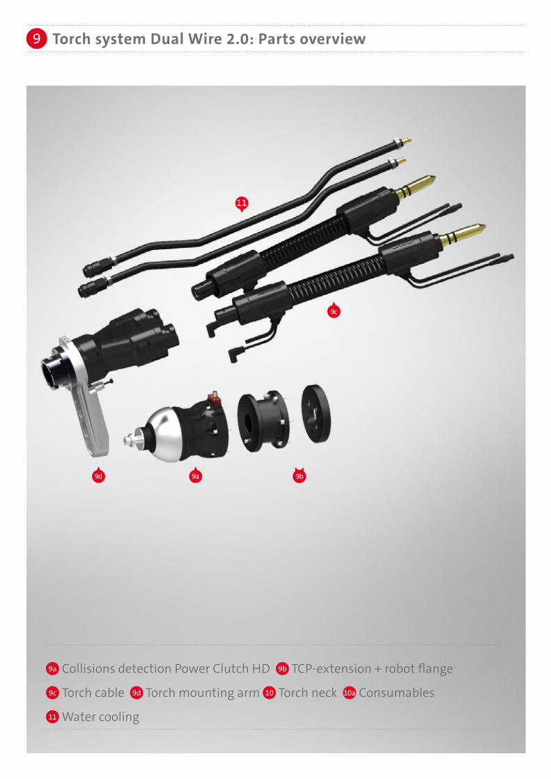
Torch system Dual Wire 2.0: Parts overview9
11
9c
9a9d 9b
9a Collisions detection Power Clutch HD 9b TCP-extension + robot flange
9c Torch cable 9d Torch mounting arm 10 Torch neck 10a Consumables
11 Water cooling
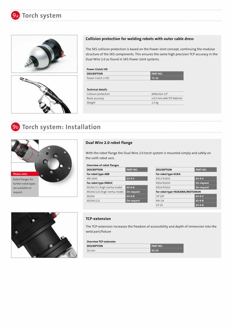
Collision protection for welding robots with outer cable dress
The SKS collision protection is based on the Power Joint concept, continuing the modularstructure of the SKS components. This ensures the same high precision TCP accuracy in theDual Wire 2.0 as found in SKS Power Joint systems.
Power Clutch HDDESCRIPTION PART-NO.Power Clutch 2 HD 71-16
Technical detailsCollision protection deflection 10°Reset accuracy ± 0.5 mm with TCP 400mmWeight 1.5 kg
Dual Wire 2.0 robot flange
With the robot flange the Dual Wire 2.0 torch system is mounted simply and safely onthe sixth robot axis.
Torch system: Installation
9a
9b
TCP-extension
The TCP-extension increases the freedom of accessibility and depth of immersion into the weld part/fixture
Overview TCP-extensionDESCRIPTION PART-NO.
50 mm 93-29
Torch system
Please note:
Robot flanges for further robot types are available on request.
Overview of robot flangesDESCRIPTION PART-NO.For robot type-ABBIRB 2600 63-4-5For robot type-FANUCM10iA/12 (high inertia mode) 63-4-8M10iA/12S (high inertia mode) On requestM20iA 63-4-8M20iA/12L On request
DESCRIPTION PART-NO.For robot type-KUKAKR12 R1810 63-4-3KR16 R1610 On requestKR16 R2010 On requestFor robot type-YASKAWA/MOTOMANHP 20F 63-4-1MH 24 63-4-8GP 25 63-4-8

Dual Wire 2.0: Torch mounting arm
Precise torch body with mounting arm, air blast connector and proven bayonet quick-changeconnectors for torch cable and torch neck
Torch mounting armDESCRIPTION PART-NO.Torch mounting arm 54-5-1
Torch system: Torch cable/Accessories
Torch system: Torch mounting arm
9c
9d
Please note: Two cable bundles are required for a single system.
Liner for torch system
For the following diameters and filler materials:
Y-Wire guidance
Wire guidance for defined guidance of both torch cables
Y-Wire guidanceDESCRIPTION PART-NO.
Y-Wire guidance 91-3-0-90
Please note:Two liners and two sleeves are requiredfor a single system. Additionally, two power pin capsare required when using aluminum wire.
Steel, bronze (wire-ø 0.8 - 1.0 mm)DESCRIPTION PART-NO.Length 2 m 44-24-0810-20Length 3.5 m 44-24-0810-35Sleeve 44-30-2
Aluminum (wire-ø 1.2 - 1.6 mm)DESCRIPTION PART-NO.per meter 91-68-47025-25ESleeve 44-30-7Power pin cap 61-2-0-2-7
Steel, bronze (wire-ø 1.2 - 1.6 mm)DESCRIPTION PART-NO.Length 2 m 44-24-1216-20Length 3.5 m 44-24-1216-35Sleeve 44-30-3
Torch cable for Dual Wire 2.0 torch systemHighly flexible coaxial cable 72 mm2 with Power Pin and Power Clutch connector including switch-off cable for the robot
Overview recommended torch cable lengths for robots
Overview torch cable length
DESCRIPTION PART-NO.For robot type-FANUCM10iA/12 (high inertia mode)(1.2m) 61-5-12M10iA/12S (high inertia mode) on requestM20iA(1,5m) 61-5-15M20iA/12L on request
For robot type-YASKAWA/MOTOMAN
HP 20F (1.2m) 61-5-12MH 24 (1.2m) 61-5-12GP 25 on request
DESCRIPTION PART-NO.For robot type-ABBIRB 2600 (1.0m) 61-5-10
For robot type-KUKA
KR12 R1810 on requestKR16 R1610 on requestKR16 R2010 on request
LENGTH PART-NO.0.75 m 61-5-0750.9 m 61-5-091.0 m 61-5-101.2 m 61-5-12
LENGTH PART-NO.1.5 m 61-5-151.8 m 61-5-182.0 m 61-5-202.4 m 61-5-24

The torch neck of the Dual Wire 2.0 torch system can be configurated with two different types of gas nozzles: For standard or heavy duty applications.
INFO
Torch necks/Accessories10
ROUND GAS NOZZLE
ALTERNATIVE
1
2
4
5
8
7
6
3
9Configuration:Standard (560 A 60 % ED/40 °C)
Configuration:Heavy duty (840 A 60 % ED/40 °C)

Torch necks for Dual Wire 2.0
SKS torch necks for easy installation with the innovative bayonet lock system for quick replacement. Aside from a toolless change of the torch neck, a TCP ± 0.5 mm is guaranteed. Two separated cooling circuits (torch neck and consumables) provide high cooling efficiency.
Overview torch neck Application recommendationsDESCRIPTION / TCP in mm PART-NO. Steel/CrNi Al*
Torch neck 15° (complete system 30°) / 550 with retaining head and clamping nut
54-5-3-15-550-1-1 √ √ √ √
Clamping cap 54-5-2-9
√ √ Recommended standard torch neck√ RecommendedO Special design: application specificX Not recommended
Further information about cooling with ordering numbers can be found in section 11 .
Torch necks/Accessories10
1
2
Welding with a single potential enables the use of a round gas nozzle with parallel wires.The advantages:
• Smaller dimensions for better accessibility in different positions (punching, dragging)• Easier programming• Use of standard cleaning equipment• Just a single Weld Process Control is necessary for the whole process. Moreover the entire system is realized with standard components. This makes the operation much easier and reduces investment.
ADVANTAGES OF SKS DUAL WIRE 2.0 SYSTEM
Torches: Consumables10a
3
4
Retaining head and clamping nut (spare part)
Heavy duty retaining head
Overview retaining headDESCRIPTION PART-NO.Retaining head (spare part) 54-5-2-12Clamping nut for retaining head (spare part) 54-5-2-13
Contact tip
• Improved heat transfer extends lifetime• Improved power transition: constant arc quality
Wire-ø CuCrZr / PART-NO.
0.9 mm 54-5-7-09S
1.0 mm 54-5-7-10S1.2 mm 54-5-7-12S1.4 mm 54-5-7-14S1.6 mm 54-5-7-16S
Overview of contact tip
Please note:Two contact tips are required for a single system.
* Please note:
For aluminum applicationsSKS recommends a Frontpull torch system

Torches: Consumables10a
Cooling jacket for consumables
Extra cooling of consumables
Cooling jacket for nozzlesDESCRIPTION PART-NO.Cooling jacket for gas nozzles 54-5-70-1
Lock nut for gas nozzle
For fixation of the gas nozzle at the cooling jacket
Lock nutDESCRIPTION PART-NO.Lock nut 54-5-70-2
Heavy duty gas nozzle with direct cooling
When using the HD gas nozzle the parts 6 , 7 , 8 aren't needed.
Heavy duty gas nozzle with direct coolingDESCRIPTION PART-NO.tapered, long, ø 18 mm 54-11-18-TRtapered, long, ø 20 mm 54-11-20-TR
Standard gas nozzles
Overview gas nozzlesDESCRIPTION PART-NO.tapered, flush, ø 18 mm 54-10-18-TFtapered, long, ø 18 mm 54-10-18-TR
Please note:An overview with dimensions can be found on the last page.
Gas diffuser Dual Wire 2.0
Gas diffuserDESCRIPTION PART-NO.Ceramics gas diffuser 54-5-20
5
9
ALTERNATIVE
6
7
8
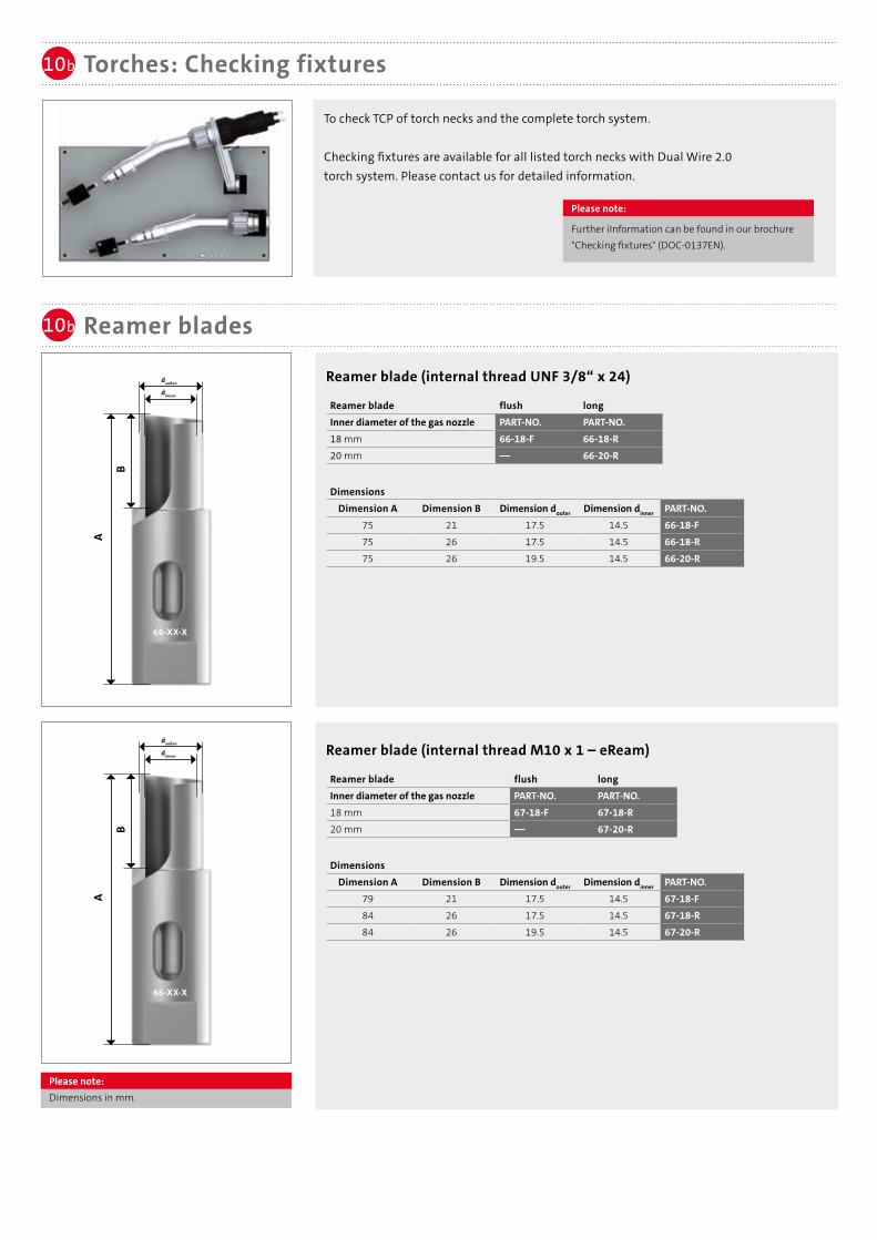
To check TCP of torch necks and the complete torch system.
Checking fixtures are available for all listed torch necks with Dual Wire 2.0 torch system. Please contact us for detailed information.
10b
Torches: Checking fixtures
Reamer blades
10b
Please note:
Further iInformation can be found in our brochure "Checking fixtures" (DOC-0137EN).
Please note:Dimensions in mm.
Reamer blade (internal thread UNF 3/8“ x 24)
Reamer blade flush longInner diameter of the gas nozzle PART-NO. PART-NO.18 mm 66-18-F 66-18-R20 mm –– 66-20-R
DimensionsDimension A Dimension B Dimension douter Dimension dinner PART-NO.
75 21 17.5 14.5 66-18-F75 26 17.5 14.5 66-18-R75 26 19.5 14.5 66-20-R
daußen
dinnen
A
B
66-XX-X
Reamer blade (internal thread M10 x 1 – eReam)
Reamer blade flush longInner diameter of the gas nozzle PART-NO. PART-NO.18 mm 67-18-F 67-18-R20 mm –– 67-20-R
DimensionsDimension A Dimension B Dimension douter Dimension dinner PART-NO.
79 21 17.5 14.5 67-18-F84 26 17.5 14.5 67-18-R84 26 19.5 14.5 67-20-R
daußen
dinnen
A
B
66-XX-X

Water conduit for Dual Wire 2.0 torch neck
The torch neck is cooled down from the inside. With this conduit the cooling unit of the torch neck is connected with the cooling circuit.
Water conduit for cooling unit of the torch neckDESCRIPTION PART-NO.Water conduit for cooling unit of the torch neck 93-11-10
Torches: Tools10c
Programming tips
Dual Wire programming tips for precise seam programming
Overview of programming tipsStickout PART-NO.18 mm 54205340020 mm 542053500
Water cooling11
Water cooling
The SKS Dual Wire 2.0 torch system comes with two separate cooling circuits to increase the cooling efficiency. The first circuit cools down the consumables while the second cooling circuit cools down the torch neck. We achieve a better cooling effect with this separation. That because the reflected energy of the welded part can be dissipated easily. The heat at the gas nozzle is already reduced and doesn’t reach the torch.The cooling equipment consists of a water flow / return for the cooling jacket for cooling down the consumables, a water conduit for cooling inside the torch neck and a water cooler with two circuits. Additionally, the system has a water flow control for safe use.
Water cooler eChilly
The water cooler eChilly has two separated cooling circuits and provides best possible cooling efficiency next to the process. Tank capacity 6.4 L.
Water coolerDESCRIPTION PART-NO.Water cooler eChilly 541018400
Socket key for Dual Wire 2.0
For replacement of retaining head
Socket key for retaining headDESCRIPTION PART-NO.Socket key for retaining head 54-5-2-8
Tool for lock nut (at cooling jacket)
Tool for lock nutDESCRIPTION PART-NO.Tool for lock nut 54-5-70-3

Water cooling11
Velcro® strip set
Set with 10 Velcro® strips, width 3 cm, for easy mounting of cables and conduits
Velcro® strip setDESCRIPTION PART-NO.Velcro® strip set 571040320
Water monitoring
For monitoring water flow
Water monitoringDESCRIPTION PART-NO.Water monitoring 93-11-0
550
343.650
185
1:5
124
10°
30°
196214
8
12 Torches: TCP dimensions
Torch 15° (complete system 30°) PART-NO. 54-5-3-15-550-1-1
Pure Electric.For a precise and regulated
cleaning of the torch
frontend
For further information
please visit
www.eReam.de
Please note:
Further iInformation can be found in our eReam brochure (DOC-0184EN).
Water cooling conduit for cooling jacket
Conduit for cooling jacket to dissipate heat from the consumables.
Water cooling conduit for cooling jacketDESCRIPTION PART-NO.Water cooling conduit for cooling jacket 71-8-16
Please note:Dimensions in mm.

Subject to change.
SKS Welding Systems GmbH | Marie-Curie-Strasse 14 | 67661 Kaiserslautern | [email protected] | www.sks-welding.com