weld study continued 9-24-07. filet weld on both sides deflection (top flange removed) stress...
TRANSCRIPT

Weld Study Continued
9-24-07
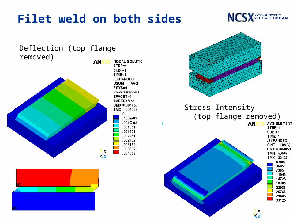
Filet weld on both sides
Deflection (top flange removed)
Stress Intensity (top flange removed)
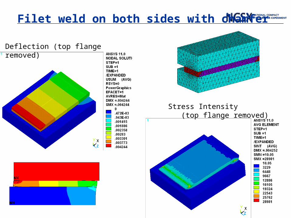
Filet weld on both sides with chamfer
Deflection (top flange removed)
Stress Intensity (top flange removed)
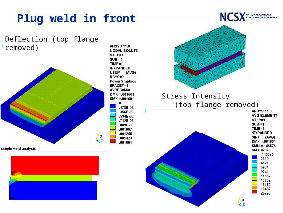
Plug weld in front
Deflection (top flange removed)
Stress Intensity (top flange removed)
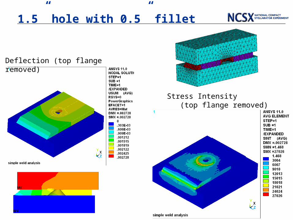
1.5” hole with 0.5” fillet
Deflection (top flange removed)
Stress Intensity (top flange removed)
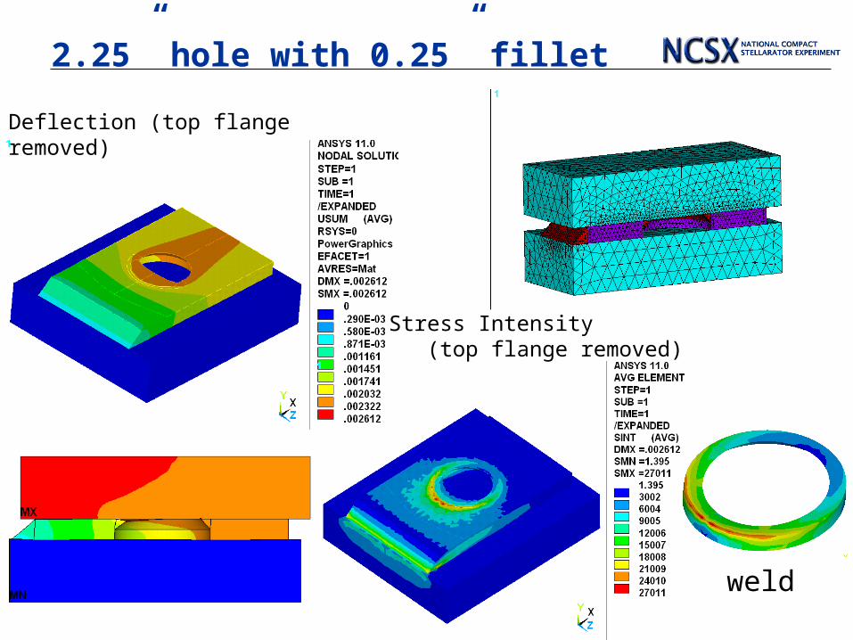
2.25” hole with 0.25” fillet
weld
Deflection (top flange removed)
Stress Intensity (top flange removed)
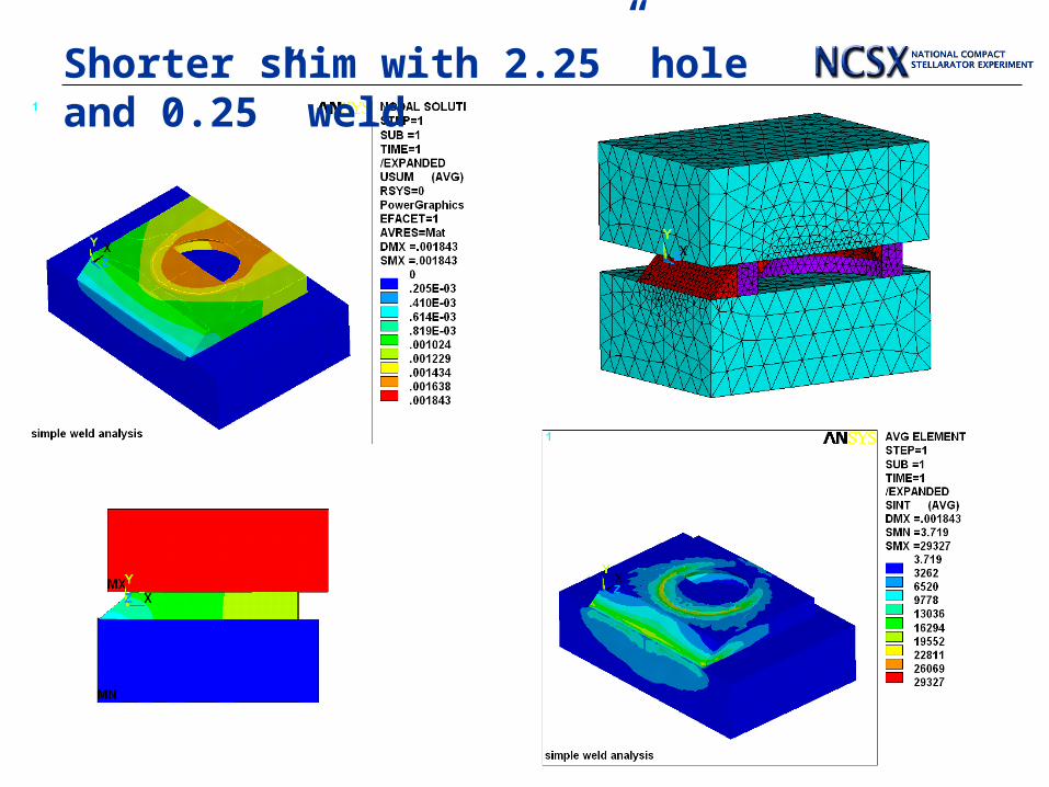
Shorter shim with 2.25” hole and 0.25” weld
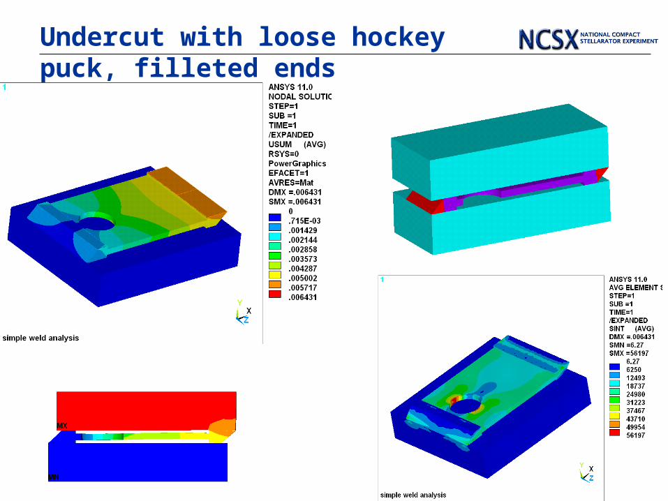
Undercut with loose hockey puck, filleted ends
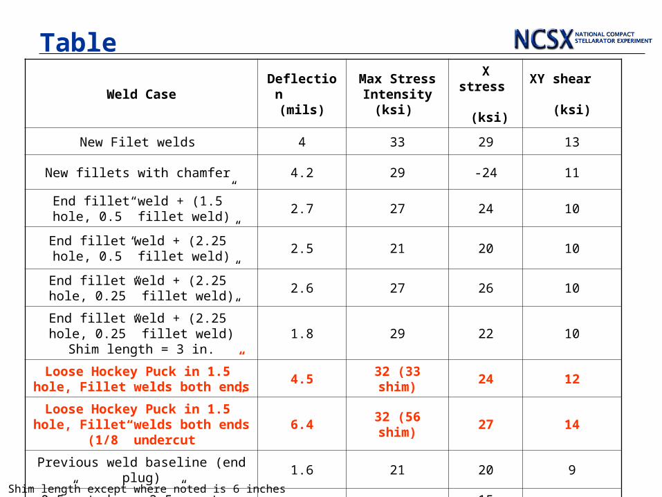
TableWeld Case
Deflection (mils)
Max Stress Intensity (ksi)
X stress (ksi)
XY shear (ksi)
New Filet welds 4 33 29 13
New fillets with chamfer 4.2 29 -24 11
End fillet weld + (1.5” hole, 0.5” fillet weld)
2.7 27 24 10
End fillet weld + (2.25” hole, 0.5” fillet weld)
2.5 21 20 10
End fillet weld + (2.25” hole, 0.25” fillet weld)
2.6 27 26 10
End fillet weld + (2.25” hole, 0.25” fillet weld) Shim length = 3 in.
1.8 29 22 10
Loose Hockey Puck in 1.5” hole, Fillet welds both ends
4.5 32 (33 shim) 24 12
Loose Hockey Puck in 1.5” hole, Fillet welds both ends (1/8”
undercut6.4 32 (56 shim) 27 14
Previous weld baseline (end plug) 1.6 21 20 9
0.5” studs on 2.5” centers with Stycast [experiment + analysis] 2006
baseline5 14
15 (bending)
16
Shim length except where noted is 6 inches
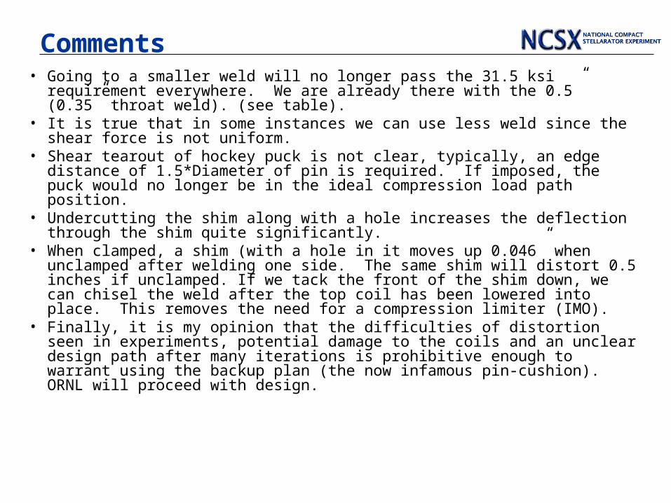
Comments• Going to a smaller weld will no longer pass the 31.5 ksi requirement
everywhere. We are already there with the 0.5” (0.35” throat weld). (see table).
• It is true that in some instances we can use less weld since the shear force is not uniform.
• Shear tearout of hockey puck is not clear, typically, an edge distance of 1.5*Diameter of pin is required. If imposed, the puck would no longer be in the ideal compression load path position.
• Undercutting the shim along with a hole increases the deflection through the shim quite significantly.
• When clamped, a shim (with a hole in it moves up 0.046” when unclamped after welding one side. The same shim will distort 0.5 inches if unclamped. If we tack the front of the shim down, we can chisel the weld after the top coil has been lowered into place. This removes the need for a compression limiter (IMO).
• Finally, it is my opinion that the difficulties of distortion seen in experiments, potential damage to the coils and an unclear design path after many iterations is prohibitive enough to warrant using the backup plan (the now infamous pin-cushion). ORNL will proceed with design.
Pin Cushion
• No Weld Distortion.• Single Piece shim(s), (no limiters)• Carries shear effectivly, shown by experiment.• Easy to use “break off studs”• Assembly sequence straight forward. No need to pull coils apart.• Can be disassembled. (spray pins with mold release, worked well in
experiment fixture)
Still need.Still need.Epoxy injection system – finalize placement of O-rings/seals, may not be
needed if using smaller discrete shims.Possibly could use filler materials in stycast to provide additional bearing
strength.
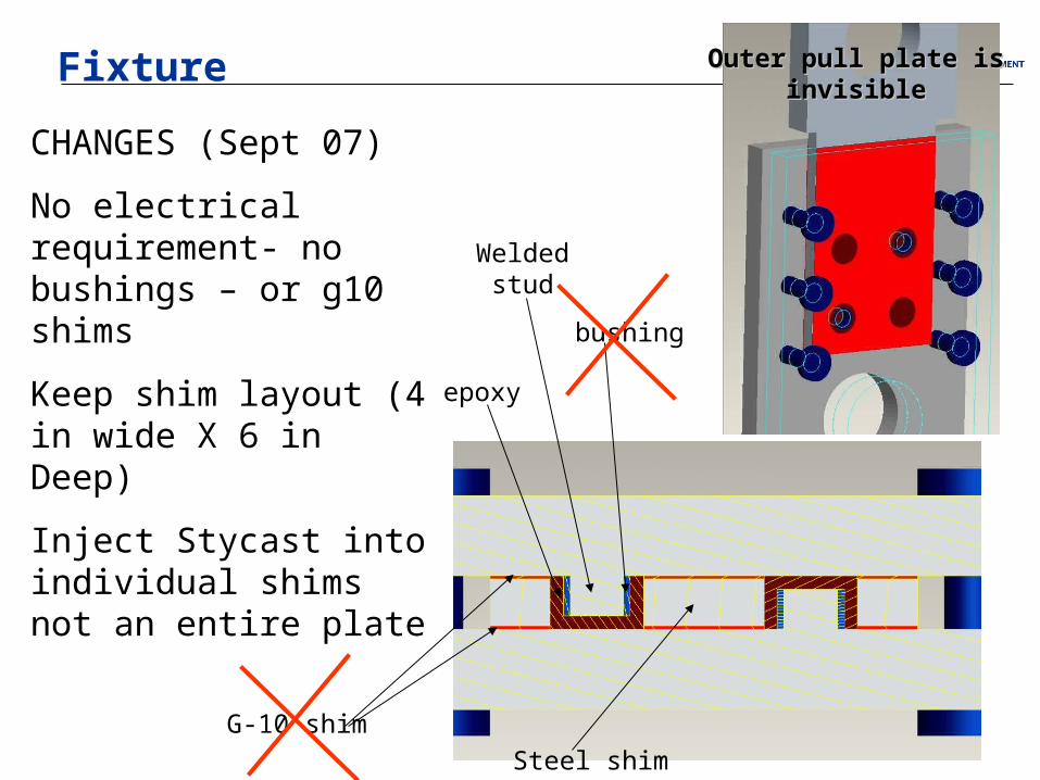
Fixture
Welded stud
bushing
epoxy
G-10 shim
Steel shim
Outer pull plate is Outer pull plate is invisibleinvisible
CHANGES (Sept 07)
No electrical requirement- no bushings – or g10 shims
Keep shim layout (4 in wide X 6 in Deep)
Inject Stycast into individual shims not an entire plate
Previous Stud Welding
• The four half inch studs were welded on at the MDL laboratory onto the two pull plates. The pins had very little tilt to them and were fairly normal to the plates.
• The weld bead was then ground off and the studs were cut back to 3/8” long.******
• This procedure can be performed at PPPL in the same manner as was done at MDL.
• All other parts of the fixture (excluding the studs), were machined at a local machine shop.
• *******Knock off studs makes this exercise very easy, even I could do it. A fixture could be made, and will be made at MDL to remove the fillet splatter, or it may be ok to remain id shim is chamfered at holes.

2 mil offset
NCSX force
Testing was conducted at double NCSX expected shear force.
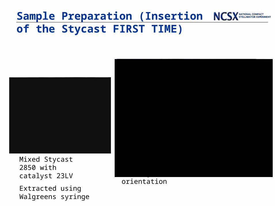
Sample Preparation (Insertion of the Stycast FIRST TIME)
Mixed Stycast 2850 with catalyst 23LV
Extracted using Walgreens syringe
Stycast was inserted from the top filling all four holes in this orientation
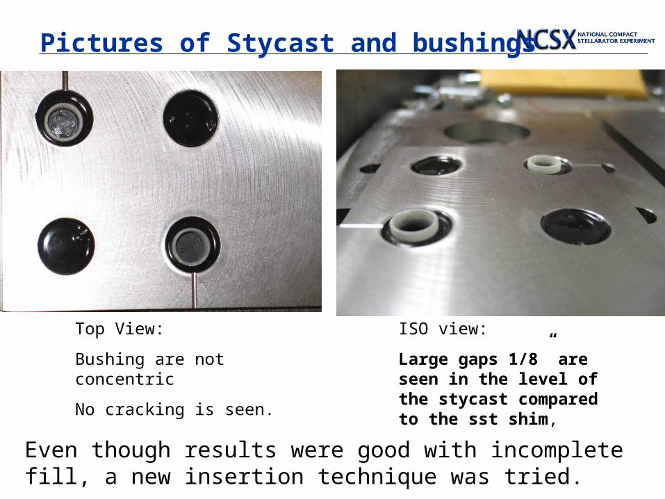
Pictures of Stycast and bushings
Top View:
Bushing are not concentric
No cracking is seen.
ISO view:
Large gaps 1/8” are seen in the level of the stycast compared to the sst shim,
Even though results were good with incomplete fill, a new insertion technique was tried.
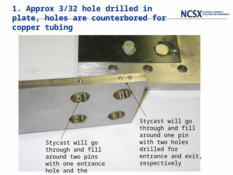
1. Approx 3/32 hole drilled in plate, holes are counterbored for copper tubing
Stycast will go through and fill around two pins with one entrance hole and the bottom and exit hole at the top
Stycast will go through and fill around one pin with two holes drilled for entrance and exit, respectively

2. Copper tubing glued in with stycast
Small Zerc-like Fittings may be used in the real coil, but stycast works just fine.
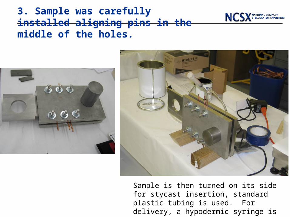
3. Sample was carefully installed aligning pins in the middle of the holes.
Sample is then turned on its side for stycast insertion, standard plastic tubing is used. For delivery, a hypodermic syringe is used.
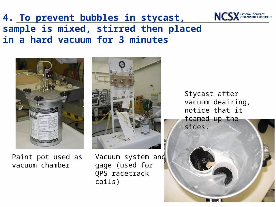
4. To prevent bubbles in stycast, sample is mixed, stirred then placed in a hard vacuum for 3 minutes
Paint pot used as vacuum chamber
Vacuum system and gage (used for QPS racetrack coils)
Stycast after vacuum deairing, notice that it foamed up the sides.
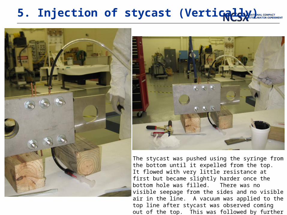
5. Injection of stycast (Vertically)
The stycast was pushed using the syringe from the bottom until it expelled from the top. It flowed with very little resistance at first but became slightly harder once the bottom hole was filled. There was no visible seepage from the sides and no visible air in the line. A vacuum was applied to the top line after stycast was observed coming out of the top. This was followed by further pushing with the syringe. No air bubbles were seen.
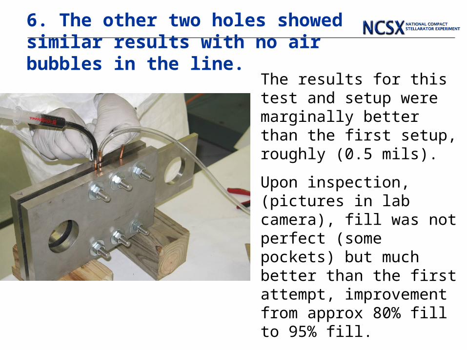
6. The other two holes showed similar results with no air bubbles in the line.
The results for this test and setup were marginally better than the first setup, roughly (0.5 mils).
Upon inspection, (pictures in lab camera), fill was not perfect (some pockets) but much better than the first attempt, improvement from approx 80% fill to 95% fill.
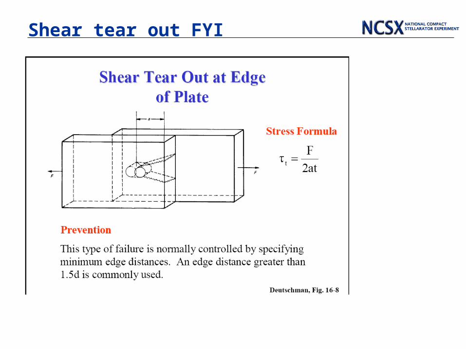
Shear tear out FYI