welding
DESCRIPTION
WeldingTRANSCRIPT

Welding ProcessesWelding Processes
Permanent Joining Processes

Weldability of a MetalWeldability of a Metal• Metallurgical Capacity
• Parent metal will join with the weld metal without formation of deleterious constituents
• Mechanical Soundness• Joint will be free from discontinuities, gas porosity,
shrinkage, slag, or cracks• Serviceability
• Weld is able to perform under varying conditions or service (e.g., extreme temperatures, corrosive environments, fatigue, high pressures, etc.)

Types of WeldingTypes of Welding
Fusion Welding Pressure Welding
Homogeneous Heterogeneous
Brazing SolderingGas Welding
High Energy Beam
Electric Arc
MIGTIG
Shielded Metal Arc – “Stick”
Friction Welding

Fusion Welding PrinciplesFusion Welding Principles
• Base metal is melted• Filler metal may be added• Heat is supplied by various means
• Oxyacetylene gas• Electric Arc• Plasma Arc• Laser

Fusion WeldingFusion Welding
BASE METAL
WELD
SOLIDIFIED SLAG
ARC POOL
WELDING ATMOSPHERE
CORE WIRE
ELECTRODE COATING
ARC STREAM
PENETRATION DEPTH

Weld Metal ProtectionWeld Metal Protection• During fusion welding, the molten metal in the
weld “puddle” is susceptible to oxidation• Must protect weld puddle (arc pool) from the
atmosphere• Methods
• Weld Fluxes• Inert Gases

Weld FluxesWeld Fluxes
• Typical fluxes• SiO2, TiO2, FeO, MgO, Al2O3
• Produces a gaseous shield to prevent contamination
• Act as scavengers to reduce oxides• Add alloying elements to the weld• Influence shape of weld bead during
solidification

Inert GasesInert Gases• Argon, helium, nitrogen, and carbon
dioxide• Form a protective envelope around the
weld area• Used in
• MIG• TIG• Shield Metal Arc
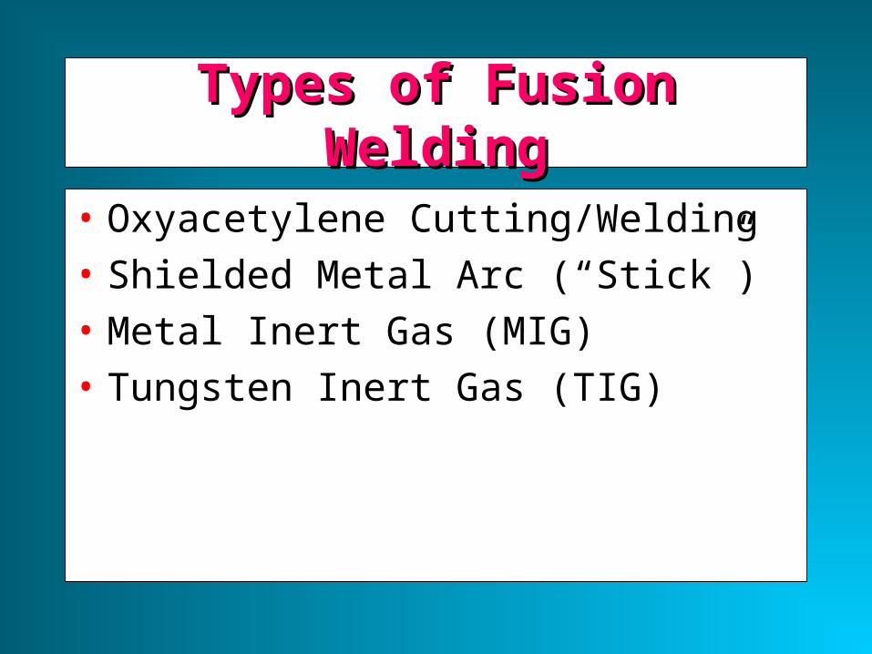
Types of Fusion WeldingTypes of Fusion Welding
• Oxyacetylene Cutting/Welding• Shielded Metal Arc (“Stick”)• Metal Inert Gas (MIG) • Tungsten Inert Gas (TIG)

Oxyacetylene Welding• Flame formed by burning a mix of acetylene
(C2H2) and oxygen
• Fusion of metal is achieved by passing the inner cone of the flame over the metal
• Oxyacetylene can also be used for cutting metals
Inner Cone: 5000-6300 deg F Combustion Envelope 3800 deg F
2300 deg FTORCH TIP

Shielded Metal Arc (Stick)• An electric arc is generated between a coated
electrode and the parent metal• The coated electrode carries the electric
current to form the arc, produces a gas to control the atmosphere and provides filler metal for the weld bead
• Electric current may be AC or DC. If the current is DC, the polarity will affect the weld size and application

Shielded Metal Arc (con’t)Shielded Metal Arc (con’t)• Process:
• Intense heat at the arc melts the tip of the electrode
• Tiny drops of metal enter the arc stream and are deposited on the parent metal
• As molten metal is deposited, a slag forms over the bead which serves as an insulation against air contaminants during cooling
• After a weld ‘pass’ is allowed the cool, the oxide layer is removed by a chipping hammer and then cleaned with a wirebrush before the next pass.

Inert Gas WeldingInert Gas Welding
• For materials such as Al or Ti which quickly form oxide layers, a method to place an inert atmosphere around the weld puddle had to be developed

• Uses a consumable electrode (filler wire made of the base metal)
• Inert gas is typically Argon
Metal Inert Gas (MIG)
BASE METAL PUDDLE
POWER SOURCE
DRIVE WHEELSCONSUMABLE ELECTRODE
ARC COLUMNSHIELDING GAS

• Tungsten electrode acts as a cathode• A plasma is produced between the tungsten cathode and the
base metal which heats the base metal to its melting point• Filler metal can be added to the weld pool
Tungsten Inert Gas (TIG)Tungsten Inert Gas (TIG)
BASE METAL PUDDLE
POWER SOURCE
ARC COLUMNSHIELDING GAS
TUNGSTEN ELECTRODE
+ +
BASE METAL (ANODE)
TUNGSTEN ELECTRODE
(CATHODE)
- - -+ +

Welding PositionsWelding Positions
FLATFLAT
HORIZONTALHORIZONTAL
VERTICALVERTICAL
OVERHEADOVERHEAD
INCREASING DIFFICULTY

Joint DesignJoint Design
BUTT JOINTBUTT JOINT
STRAP JOINT
LAP JOINT
FILLET JOINT
CORNER JOINT
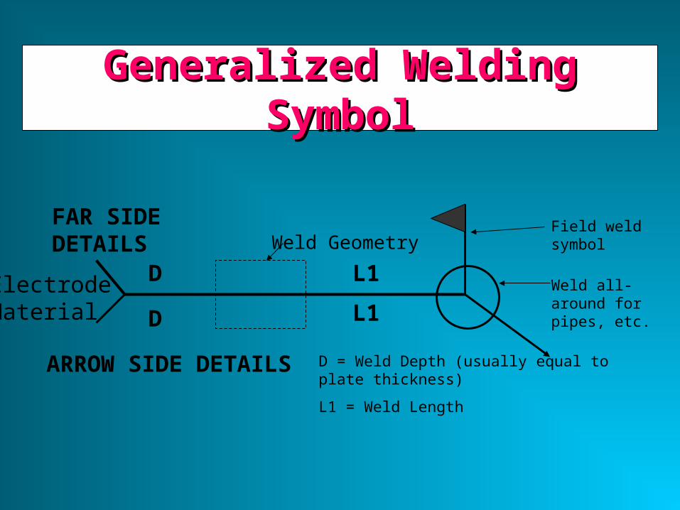
Generalized Welding SymbolGeneralized Welding Symbol
FAR SIDE DETAILS
ARROW SIDE DETAILS
Field weld symbol
Weld all-around for pipes, etc.
L1
L1
D = Weld Depth (usually equal to plate thickness)
L1 = Weld Length
ElectrodeMaterial
D
D
Weld Geometry

Example Welding SymbolExample Welding Symbol
1/2” 1/2”
1/2
1/2
One-sided welds are max 80% efficientTwo sided are 100% efficient
Geometry symbol for V-groove

Weld Symbols (Butt Joints)Weld Symbols (Butt Joints)
Backing

Weld Symbol (Fillet Joints)Weld Symbol (Fillet Joints)

Weld Symbol (Corner Joints)Weld Symbol (Corner Joints)

Welding Defects