well decommissioning guidelines
TRANSCRIPT

Well Decommissioning
Guidelines VERSION 1.0: November 2021

Page: 2
BC Oil and Gas Commission V 1.0: November 2021
Uncontrolled copy once downloaded
GoTo: Table of Contents | Glossary | Legislation | BCOGC.CA
Well Decommissioning Guidelines
About the Commission
The BC Oil and Gas Commission (Commission) is the single-window regulatory agency
with responsibilities for regulating oil and gas activities in British Columbia, including
exploration, development, pipeline transportation and reclamation.
The Commission’s core roles include reviewing and assessing applications for industry
activity, consulting with First Nations, ensuring industry complies with provincial legislation
and cooperating with partner agencies. The public interest is protected by ensuring public safety,
protecting the environment, conserving petroleum resources and ensuring equitable participation in production.
VISION
Safe and responsible energy resource development for British Columbia.
MISSION
We provide British Columbia with regulatory excellence in responsible energy resource development by
protecting public safety, safeguarding the environment and respecting those individuals and communities who
are affected.
VALUES
Transparency
Is our commitment to be open and provide clear information on decisions,
operations and actions.
Innovation
Is our commitment to learn, adapt, act and grow.
Integrity
Is our commitment to the principles of fairness, trust and accountability.
Respect
Is our commitment to listen, accept and value diverse perspectives.
Responsiveness
Is our commitment to listening and taking timely and meaningful action.

Page: 3
BC Oil and Gas Commission V 1.0: November 2021
Uncontrolled copy once downloaded
GoTo: Table of Contents | Glossary | Legislation | BCOGC.CA
Well Decommissioning Guidelines
Commission Guidelines
As with all Commission documents, this manual does not take the place of applicable legislation. Readers are
encouraged to become familiar with the acts and regulations and seek direction from Commission staff for
clarification. Some activities may require additional requirements and approvals from other regulators or create
obligations under other statutes. It is the applicant and permit holder’s responsibility to know and uphold all legal
obligations and responsibilities.
Throughout the manual there are references to guides, forms, tables and definitions to assist in creating and
submitting all required information. Additional resources include:
• Glossary and acronym listing on the Commission website.
• Documentation and guidelines on the Commission website.
• Frequently asked questions on the Commission website.
• Advisories, bulletins, reports and directives on the Commission website.
• Regulations and Acts listed on the Commission website
Page: 4
BC Oil and Gas Commission V 1.0: November 2021
Uncontrolled copy once downloaded
GoTo: Table of Contents | Glossary | Legislation | BCOGC.CA
Well Decommissioning Guidelines
Table of Contents
About the Commission ...................................................................................................................................... 2
Commission Guidelines .................................................................................................................................... 3
Table of Contents ......................................................................................................................................................... 4
Manual Revisions ............................................................................................................................................. 7
Chapter 1: Introduction ..................................................................................................................................... 8
1.1 Purpose ......................................................................................................................................................... 8
1.2 Notification and Reporting ................................................................................................................................ 8
1.3 Routine vs Non-Routine................................................................................................................................... 9
Chapter 2: Previously Decommissioned Wells and Abandoned Zones ................................................................ 10
2.1 Previously Decommissioned Wells ................................................................................................................. 10
2.2 Previously Abandoned Zones ......................................................................................................................... 10
2.2.1 Level A Intervals ........................................................................................................................................... 10
2.2.2 Leaking Zonal Abandonment Plugs ................................................................................................................ 10
2.3 Abandoned Well Leaks .................................................................................................................................. 11
2.4 Well Re-entry ............................................................................................................................................... 11
Chapter 3: Open-hole Abandonment Requirements .......................................................................................... 12
3.1 Overview...................................................................................................................................................... 12
3.2 Open-hole Abandonment Plug Placement ....................................................................................................... 12
3.3 Verifying Open-hole Plug Placement ............................................................................................................... 13
Chapter 4: Cased-hole Abandonment Requirements ......................................................................................... 14
4.1 Overview...................................................................................................................................................... 14
4.1.1 Definition of Level A Intervals ......................................................................................................................... 14
4.1.2 Definition of High Pressure Intervals ............................................................................................................... 14
4.2 Cement Evaluation ........................................................................................................................................ 15
4.3 Identification and Isolation of Porous Intervals ................................................................................................. 15
4.4 Use and Placement of Bridge Plugs ................................................................................................................ 15
4.5 Noncompleted Wells Without Liners................................................................................................................ 16
4.6 Zonal Abandonment in a Completed Well ........................................................................................................ 16
4.6.1 Capping a Bridge Plug with Cement (Non-Level A Intervals) ............................................................................. 17
Page: 5
BC Oil and Gas Commission V 1.0: November 2021
Uncontrolled copy once downloaded
GoTo: Table of Contents | Glossary | Legislation | BCOGC.CA
Well Decommissioning Guidelines
4.6.2 Capping a Bridge Plug with Cement (Level A Intervals, Non-Routine) ................................................................ 17
4.6.3 Setting a Cement Plug or Squeezing Cement (Non-Level A Intervals) ................................................................ 17
4.6.4 Squeezing a Cement Plug (Level A Intervals) .................................................................................................. 18
4.6.5 Squeezing Cement Using a Cement Retainer (Non-Level A Intervals) ................................................................ 18
4.6.6 Squeezing Cement Using a Cement Retainer (Level A Intervals) ....................................................................... 19
4.7 Wells with a Cemented Liner .......................................................................................................................... 19
4.7.1 Capping a Bridge Plug with Cement (Non-Level A Intervals) ............................................................................. 19
4.7.2 Capping a Bridge Plug with Cement (Level A Intervals, Non-Routine) ................................................................ 20
4.7.3 Setting a Cement Plug or Squeezing Cement .................................................................................................. 20
4.8 Wells with an Uncemented Liner .................................................................................................................... 20
4.9 Open-hole Completions in Horizontal Wells ..................................................................................................... 21
4.9.1 Single Formation Horizontal Wells .................................................................................................................. 21
4.9.2 Multiple Formation Horizontal Wells ................................................................................................................ 21
4.10 Casing Failures, Previously Cement Squeezed Intervals ................................................................................... 21
4.11 Surface Casing Vent Flow, Gas Migration Repair ............................................................................................. 22
4.11.1 Routine SCVF or GM Repairs ........................................................................................................................ 22
4.12 Groundwater Protection ................................................................................................................................. 23
4.12.1 Removing Casing and Setting a Cement Plug (Non-Routine) ............................................................................ 23
4.12.2 Remedial Cementing ..................................................................................................................................... 24
4.13 Use of Alternative Materials and Techniques ................................................................................................... 25
Chapter 5: Logging and Testing Requirements ................................................................................................. 26
5.1 Cement Plug Verification ............................................................................................................................... 26
5.1.1 Tagging with Drill Pipe or Work String ............................................................................................................. 26
5.1.2 Direct Density or Hydrostatic Pressure Plug Logging ........................................................................................ 26
5.1.3 Radioactive Tracer Logging ........................................................................................................................... 27
5.2 Mechanical and Cement Plug Pressure Testing ............................................................................................... 27
Chapter 6: Surface Decommissioning .............................................................................................................. 28
6.1 Overview...................................................................................................................................................... 28
6.2 Fluids Within the Wellbore ............................................................................................................................. 28
6.3 Open-hole Fluid Level Testing ........................................................................................................................ 28
6.4 Geotechnical Stability .................................................................................................................................... 29

Page: 6
BC Oil and Gas Commission V 1.0: November 2021
Uncontrolled copy once downloaded
GoTo: Table of Contents | Glossary | Legislation | BCOGC.CA
Well Decommissioning Guidelines
6.5 Surface Casing Vent Flow Testing .................................................................................................................. 29
6.6 Gas Migration Testing ................................................................................................................................... 29
6.7 Cutting and Capping ..................................................................................................................................... 30
6.7.1 Cut and Cap not Previously Reported ............................................................................................................. 30
Appendix A: Examples of Decommissioned Cased Wells ............................................................................. 31
Appendix B: Examples of Disposal Fluids Requiring Level A Zonal Abandonment .......................................... 34

Page: 7
BC Oil and Gas Commission V 1.0: November 2021
Uncontrolled copy once downloaded
GoTo: Table of Contents | Glossary | Legislation | BCOGC.CA
Well Decommissioning Guidelines
Manual Revisions
The Commission is committed to the continuous improvement of its documentation. Revisions to the
documentation are highlighted in this section and are posted to the Documentation Section of the Commission’s
website. Stakeholders are invited to provide input or feedback on Commission documentation to
[email protected] or submit feedback using the feedback form.
Version
Number
Posted
Date
Effective
Date
Chapter
Section
Summary of
Revision(s)
1.0 November
2021
January
2022 - Initial publication

Page: 8
BC Oil and Gas Commission V 1.0: November 2021
Uncontrolled copy once downloaded
GoTo: Table of Contents | Glossary | Legislation | BCOGC.CA
Well Decommissioning Guidelines
Chapter 1: Introduction
1.1 Purpose
This document provides guidance to permit holders regarding well decommissioning practices, including zonal
abandonment, surface casing vent flow (SCVF) or gas migration (GM) repairs, groundwater protection and surface
decommissioning. Permit holders are expected to meet or exceed these guidelines in order to comply with the
requirements of section 26 of the Drilling and Production Regulation (DPR), which include the isolation of porous
intervals, ensuring fluids do not leak from the wellbore and ensuring the long term integrity of the well.
1.2 Notification and Reporting
Under section 26 (1) (a) of the DPR, a permit holder must submit a Notice of Operations (NOO) and a plugging
program to the Commission at least 7 calendar days before commencement of operations. This notification is to be
submitted electronically through eSubmission and include a completed copy of the Cased Hole Abandonment
Notification Data Sheet, a wellbore diagram and a complete program of activities to be undertaken. Permit holders
may submit NOOs before the regulatory minimum 7 days to allow for modifications to be made, if necessary.
Under section 26 (1) (c) of the DPR, a permit holder must submit an abandonment report to the Commission within
30 days of the completion of activities. This report must include a completed copy of the Completion/Workover
Report Form, a complete record of the daily reports including all significant operations undertaken, a downhole
schematic illustrating the configuration of the well at the end of the operation and any other information respecting the
work conducted. If the abandonment report includes surface decommissioning, a photograph of the cut & capped
casing stub including identifying information welded thereon must be included in the Completion/Workover Report.
The Report is submitted electronically through eSubmission and is reconciled against a previously-submitted NOO.
If a well is decommissioned prior to the release of the drilling rig, no advance notification is required, though permit
holders are encouraged to consult with the Commission’s Drilling and Production staff prior to completing downhole
abandonment operations. If surface decommissioning, including the final cut and cap, is not completed and reported
on the Summary Report of Drilling Operations (SRDO), the well is not considered to be decommissioned. In those
cases, surface decommissioning activities must be reported separately as though the well were cased.

Page: 9
BC Oil and Gas Commission V 1.0: November 2021
Uncontrolled copy once downloaded
GoTo: Table of Contents | Glossary | Legislation | BCOGC.CA
Well Decommissioning Guidelines
1.3 Routine vs Non-Routine
“Routine” and “non-routine” are used to describe zonal abandonment or wellbore remediation operations that form
part of a well decommissioning program. Operations are routine if the proposed method is one that is described in
this guideline. Operations are non-routine if the proposed method is identified in this guideline as being non-routine,
or if the proposed method differs from one described in this guideline. When planning to complete a zonal
abandonment or remedial operation in a well, a permit holder must determine whether a given operation is routine or
non-routine prior to submitting an NOO.
Please Note:
Permit holders will be expected to demonstrate that a proposed non-routine zonal abandonment method will
meet or exceed the results that would be obtained by conducting a routine zonal abandonment. Permit holders
are encouraged to contact the Commission’s Drilling & Production staff (individually, or via
[email protected]) prior to submitting a decommissioning program that includes one or more
non-routine zonal abandonments.
Some examples of non-routine zonal abandonments include, but are not limited to:
• Abandonment plugs set higher than the specified maximum allowable distance above a completed interval;
• Abandonment plugs set in such a manner that porous intervals (not in pressure communication with the
completed interval) behind cemented casing are located between the plug and the completed interval being
abandoned;
• Multiple completed intervals being abandoned beneath a single plug, whether previously approved for
commingled production or not;
• The use of a zonal abandonment method shallower than the Base of Usable Groundwater (BUGW, as
defined in INDB 2016-09) or the surface casing shoe, including for the remediation of shallow casing
failures;
• The use of materials other than class “G” cement or resin-based low permeability cement;
• Re-abandonment due to a leaking zonal abandonment plug.
Page: 10
BC Oil and Gas Commission V 1.0: November 2021
Uncontrolled copy once downloaded
GoTo: Table of Contents | Glossary | Legislation | BCOGC.CA
Well Decommissioning Guidelines
Chapter 2: Previously Decommissioned Wells and
Abandoned Zones
2.1 Previously Decommissioned Wells
Wells that were decommissioned to the standards in place prior to this edition of the Well Decommissioning
Guidelines are not required to be brought up to current standards. The exceptions to this are for cases where an
Abandoned Well Leak (AWL) develops, or where a wellbore is being re-entered for another purpose resulting in the
removal of existing plugs.
2.2 Previously Abandoned Zones
Non-decommissioned wells with zonal abandonments that were compliant at the time of the abandonment operation
are not required to be re-abandoned to current standards, except where either a Level A interval, as described in
section 4.1, is involved, or where the existing abandonment plugs are leaking. Permit holders are encouraged to
assess the condition of all abandonment plugs, especially those that were compliant in the past but are no longer.
2.2.1 Level A Intervals
Where a well has a completed Level A interval that has not been isolated by an acceptable method from this
guideline, an additional cement plug must be circulated in place. This plug must be as close to the top of the
uppermost zonal abandonment plug as possible, must be a minimum length of 30 vertical metres and have
a minimum volume of 1 m3.
If the uppermost abandonment plug is located above the BUGW, it must be drilled out and the additional
cement plug described above must be placed on the abandonment plug below. The rest of the well must
then be isolated as described in the rest of this guideline.
2.2.2 Leaking Zonal Abandonment Plugs
Where an existing zonal abandonment has been found to be leaking, that zonal abandonment must be
brought up to current standards. This may include removing the previous abandonment plug and replacing
it, or using another zonal abandonment method altogether.

Page: 11
BC Oil and Gas Commission V 1.0: November 2021
Uncontrolled copy once downloaded
GoTo: Table of Contents | Glossary | Legislation | BCOGC.CA
Well Decommissioning Guidelines
2.3 Abandoned Well Leaks
Permit holders must submit an AWL report in eSubmission if a decommissioned well is found to be leaking. This
report must include all relevant information, including a brief summary of any investigation performed and the
completion of all fields as described in the eSubmission User Guide.
Please Note:
Submissions cannot be made against a well that has a Certificate of Restoration (COR). Permit holders must
contact the Commission’s Drilling and Production staff for assistance prior to submitting an AWL report or
NOO.
Following the submission of an AWL report, the permit holder must:
• Submit an NOO for any further investigatory and/or repair work required to repair the leak;
• Notify the mineral rights owners if not held by the permit holder, or the Ministry of Energy, Mines and
Petroleum Resources (MEMPR) if they have reverted to the Crown;
• Have a surface access agreement prior to commencing operations on the well;
• Submit a SCVF or GM report via eSubmission, if the AWL is found to be a result of SCVF and/or GM;
• Repair the leak in accordance with the requirements of section 4.11 in this guideline and section 9.7 in the
Oil and Gas Activities Operations Manual.
2.4 Well Re-entry
Wells that are decommissioned and later re-entered, for example for disposal evaluation, must be decommissioned
in accordance with this guideline from the re-entry depth to surface. If there are abandoned zones below the re-entry
depth, the requirements set out under section 2.2 apply.
Page: 12
BC Oil and Gas Commission V 1.0: November 2021
Uncontrolled copy once downloaded
GoTo: Table of Contents | Glossary | Legislation | BCOGC.CA
Well Decommissioning Guidelines
Chapter 3: Open-hole Abandonment Requirements
3.1 Overview
For the downhole abandonment of an open-hole well, the permit holder must set cement plugs of sufficient length
and number to:
• Cover all usable groundwater intervals from surface to the BUGW, which may include the use of cemented
surface casing, and
• Isolate or cover all porous intervals from BUGW to the total depth of the well.
Porous intervals are defined as:
• Carbonates with effective porosity greater than 1 percent;
• Sandstones with effective porosity greater than 3 percent;
• An interval with production, injection or disposal occurring in an adjoining spacing area, regardless of the
porosity;
• An interval containing hydrocarbons capable of producing as an unconventional zone;
• Any zone with drillstem test formation liquid recoveries greater than 300 linear metres or gas volumes
greater than 300 m3.
3.2 Open-hole Abandonment Plug Placement
When conducting open-hole zonal abandonments, permit holders must ensure the following:
• Well logs, if available, are used to determine plug placement for zones deeper than the BUGW.
• All open hole cement plugs are circulated in place, using best practices to ensure plug stability.
• Plugs run at a depth less than 1500 metres TVD are a minimum length of 30 vertical metres and extended a
minimum of 15 vertical metres above and below the zone being covered.
• Plugs run at a depth more than 1500 metres TVD are a minimum length of 60 vertical metres and extended
a minimum of 30 vertical metres above and below the zone being covered.
• The uppermost plug that contacts an uncased portion of the wellbore must extend a minimum of 15 vertical
metres above the casing shoe of the deepest casing set.
A plug may extend over more than one zone. Plugs may be run in stages, but the break between stages may only
occur within a given zone, and be as far from a zone top as practical. There is no maximum distance between plugs,
however the formation fracture pressure of any interval below a given open hole plug must not be exceeded by the
in-situ pressure of any porous interval that is below that same plug.

Page: 13
BC Oil and Gas Commission V 1.0: November 2021
Uncontrolled copy once downloaded
GoTo: Table of Contents | Glossary | Legislation | BCOGC.CA
Well Decommissioning Guidelines
In a well where intermediate casing has been set, but not cemented above the shoe of the previous casing string, the
uncemented interval must be evaluated as follows:
• If the BUGW has not been covered by surface casing and the intermediate casing cement top is below the
BUGW, remedial cementing must be conducted to cover usable groundwater.
• If there are porous intervals not covered by the intermediate casing cement, remedial cementing must be
conducted to cover and/or isolate the interval.
Refer to Appendix A for an example of remedial cementing.
3.3 Verifying Open-hole Plug Placement
Permit holders must verify the location of all open-hole plugs using one of the methods described in section 5.1. The
only exceptions to this requirement are if:
• A continuous cement plug is placed from total depth to surface, in one or more stages, provided there was
no loss of circulation;
• The uppermost plug, in a well being abandoned with multiple plugs, is being circulate to surface;
• A single stage of a multistage plug is being placed, provided there is no loss of circulation.
o The final stage of a multistage plug must always be verified, unless its top is located at surface
If the location of the plug cannot be verified, or if verification indicates the placement of the plug does not comply with
the requirements laid out in section 3.2, the permit holder must correct the incorrectly placed plug and verify its
location. This may require the plug be built up, drilled or circulated out, or other remedial action as appropriate.

Page: 14
BC Oil and Gas Commission V 1.0: November 2021
Uncontrolled copy once downloaded
GoTo: Table of Contents | Glossary | Legislation | BCOGC.CA
Well Decommissioning Guidelines
Chapter 4: Cased-hole Abandonment Requirements
4.1 Overview
For the downhole abandonment of a cased-hole well, the permit holder must:
• Ensure all usable groundwater is covered by cement, or where coverage cannot be achieved, isolated from
below and above;
• Ensure isolation between all porous intervals behind casing,
• Establish isolation between all completed intervals,
• Determine whether any uncompleted intervals, particularly uncompleted Level A, high pressure, or
hydrocarbon-bearing unconventional zones require isolation.
The plugging requirements for a cased-hole well will depend on whether:
• The well was completed;
• The well was completed in an interval that is classified as Level A, as defined below;
• The well was completed in an interval that meets the definition of a high pressure interval, as defined below;
• The well has a history of integrity issues, including casing failure, SCVF or GM.
4.1.1 Definition of Level A Intervals
For the purposes of the guideline, Level A intervals are those that:
• Have been used for disposal of Class 1a or 1b fluids, as described in Appendix B;
• Have been used for disposal of acid gas or storage of CO2, including wells completed in a pool
approved for acid gas disposal or CO2 storage;
• Have a representative H2S concentration greater than or equal to 15 percent; or
• Have ever met the criteria for designation as Special Sour, as defined in the Oil and Gas Activity
Application Manual.
4.1.2 Definition of High Pressure Intervals
For the purposes of the guideline, high pressure intervals are those that:
• Have an original pressure gradient in excess of 14 kPa/m, measured from surface;
• Have been used for injection or disposal and where the pool pressure at time of abandonment
exceeds the pool discovery pressure.
Page: 15
BC Oil and Gas Commission V 1.0: November 2021
Uncontrolled copy once downloaded
GoTo: Table of Contents | Glossary | Legislation | BCOGC.CA
Well Decommissioning Guidelines
4.2 Cement Evaluation
Permit holders must assess the condition of cement behind casing prior to beginning downhole abandonment
operations. Cement evaluation logs must be run unless there is sufficient evidence to demonstrate that primary
cementing has resulted in adequate hydraulic isolation along the entire wellbore. Some factors to consider include,
but are not limited to:
• The presence of SCVF or GM;
• Theoretical calculations of cement top, or absence of cement returns to surface;
• Partial or total loss of returns during cementing.
Permit holders are encouraged to refer DACC IRPs 25, 26 and 27 for additional information on evaluating cement.
4.3 Identification and Isolation of Porous Intervals
Permit holders must identify porous intervals encountered in the well and determine whether hydraulic isolation has
been established between them. Porous intervals are defined as:
• Carbonates with effective porosity greater than 1 percent;
• Sandstones with effective porosity greater than 3 percent;
• An interval with production, injection or disposal occurring in an adjoining spacing area, regardless of the
porosity;
• An interval containing hydrocarbons capable of producing as an unconventional zone;
• Any zone with drillstem test formation liquid recoveries greater than 300 linear metres or gas volumes
greater than 300 m3
Where it cannot be determined that hydraulic isolation has been established between porous intervals, remedial
operations must take place.
4.4 Use and Placement of Bridge Plugs
For the purposes of completing a zonal abandonment of an interval that is not Level A, when a bridge plug is being
used to support a column of cement, that plug must be:
• Set less than 15 vertical metres above the interval to be abandoned; or
• Set at a depth where all of the following are met:
o The depth is within the same formation as the completed interval, or within the next formation
provided there are no other porous intervals between the bridge plug and the completed interval

Page: 16
BC Oil and Gas Commission V 1.0: November 2021
Uncontrolled copy once downloaded
GoTo: Table of Contents | Glossary | Legislation | BCOGC.CA
Well Decommissioning Guidelines
o The cement top behind the casing extends above the top of the formation in which the bridge plug
will be set
o The depth is below the BUGW.
The bridge plug must then be pressure tested as described in section 5.2, before being capped with the required
amount of cement. If more than one year has elapsed between the setting and pressure testing of the bridge plug
and the placement of cement, the plug must be pressure tested again prior to placing cement.
Please Note:
Numerous sections in this Chapter make reference to “bridge plug” as a means of achieving isolation prior to
placing cement. For the purposes of serving as a platform to support a column of cement, permit holders may
elect to use permanent or retrievable bridge plugs, permanent or retrievable packers with a plug in the packer,
or a non-activated cement retainers, provided that all other requirements are met, including pressure testing
of the platform. Note that at all times, responsibility for the well and well operations remains with the permit
holder, including responsibility to re-enter the well should repairs be necessary.
4.5 Noncompleted Wells Without Liners
Noncompleted wells without liners (ie. only have full-length casing) must be pressure tested as described in section
5.2. If the well is pressure tested successfully, no additional plugs are required. Note that remedial operations may
still be required.
4.6 Zonal Abandonment in a Completed Well
Permit holders must determine which of the following categories a completed interval proposed for abandonment
belongs to:
• Non-Level A, non-high pressure;
• Non-Level A, high pressure;
• Level A intervals; including wells completed in an acid gas disposal pool but not used for acid gas disposal;
After determining which category a completed interval belongs to, permit holders must abandon the completed
interval using one of the options outlined below.
Please Note:
Numerous sections in this chapter refer to conducting cement squeezes. Permit holders should consider the
formation fracture pressure of any interval being treated when designing a cement squeeze.
Page: 17
BC Oil and Gas Commission V 1.0: November 2021
Uncontrolled copy once downloaded
GoTo: Table of Contents | Glossary | Legislation | BCOGC.CA
Well Decommissioning Guidelines
4.6.1 Capping a Bridge Plug with Cement (Non-Level
A Intervals)
A bridge plug must be set as described in section 4.4 and pressure tested as described in section 5.2. The
plug must be capped with either a minimum of 8 vertical metres class “G” cement, or a minimum of 3 vertical
metres resin-based low-permeability cement.
Additional requirements for high pressure intervals: The cement cap must be a minimum of 60 vertical
metres in length, have a minimum volume of 1 m3, and be circulated in place.
4.6.2 Capping a Bridge Plug with Cement (Level A
Intervals, Non-Routine)
A cement evaluation log must be run from the proposed bridge plug setting depth to a minimum of 60
metres above the formation top. The bond log and an interpretation from a qualified professional must be
submitted to the Commission for review. If the interpretation confirms that isolation exists, the permit holder
must set a bridge plug less than 15 vertical metres above the completed interval. The bridge plug must then
be pressure tested as described in section 5.2. The plug must be capped with a class “G” cement plug that
is:
• Circulated in place,
• Minimum 60 vertical metres in length,
• Extends a minimum of 60 vertical metres above the formation top, and
• Has a minimum volume of 1 m3.
4.6.3 Setting a Cement Plug or Squeezing Cement
(Non-Level A Intervals)
A cement plug must be circulated in place that extends from at least 15 vertical metres above and below the
completed interval. One or more completed intervals may be covered by a single cement plug. The location
of the plug must be verified using one of the methods described in section 5.1. The plug must be pressure
tested as described in section 5.2. Permit holders should use best practices when circulating to ensure plug
stability, which may include placing a mechanical plug to act as a competent base to prevent the cement
from settling due to density differences.

Page: 18
BC Oil and Gas Commission V 1.0: November 2021
Uncontrolled copy once downloaded
GoTo: Table of Contents | Glossary | Legislation | BCOGC.CA
Well Decommissioning Guidelines
If the permit holder elects to apply a squeeze pressure to the cement, the Commission recommends that the
final squeeze pressure be a minimum of 7000 kPa above the current reservoir pressure of the highest
pressure completed interval.
Additional requirements for high pressure intervals: The cement plug must extend a minimum of 60
vertical metres above the top of the uppermost completed interval, have a minimum volume of 1 m3 and be
circulated in place.
4.6.4 Squeezing a Cement Plug (Level A Intervals)
A cement plug must be circulated in place and squeezed into the completed interval. This plug must also:
• Extend from at least 15 vertical metres below the completed interval to at least 30 vertical metres
above the formation top;
• Have a minimum volume of 1 m3;
• Be squeezed to a minimum of 7000 kPa above the current reservoir pressure of the interval being
abandoned;
• Have its location verified using one of the methods described in section 5.1;
• Be pressure tested using one of the methods described in section 5.2.
Permit holders should use best practices when circulating to ensure plug stability, which may include placing
a mechanical plug to act as a competent base to prevent the cement from settling due to density
differences.
4.6.5 Squeezing Cement Using a Cement Retainer
(Non-Level A Intervals)
A cement retainer must be set less than 15 vertical metres above the completed interval. The retainer must
be pressure tested as described in section 5.2. A cement squeeze must be conducted through the retainer,
meeting the following requirements:
• The minimum cement volume must equal the casing volume from the bottom of the retainer to the
bottom of the completed interval, plus 0.5 m3; and
• The final squeeze pressure must be a minimum of 7000 kPa above the current reservoir pressure
of the interval being abandoned.
The retainer must be capped with a minimum of 8 vertical metres class “G” cement, or a minimum of 3
vertical metres of resin-based low-permeability cement

Page: 19
BC Oil and Gas Commission V 1.0: November 2021
Uncontrolled copy once downloaded
GoTo: Table of Contents | Glossary | Legislation | BCOGC.CA
Well Decommissioning Guidelines
4.6.6 Squeezing Cement Using a Cement Retainer
(Level A Intervals)
A cement retainer must be set less than 15 vertical metres above the completed interval. The retainer must
be pressure tested as described in section 5.2. A cement squeeze must be conducted through the retainer,
meeting the following requirements:
• The minimum cement volume must equal the casing volume from the bottom of the retainer to the
bottom of the completed interval, plus 0.5 m3; and
• The final squeeze pressure must be a minimum of 7000 kPa above the current reservoir pressure
of the interval being abandoned.
The retainer must be capped with a class “G” cement plug that:
• Is circulated in place,
• Is a minimum 30 vertical metres in length,
• Extends a minimum of 30 vertical metres above the formation top, and
• Has a minimum volume of 1 m3.
4.7 Wells with a Cemented Liner
Completed intervals located below the liner top of a cemented liner must be abandoned as described in section 4.6.
Following abandonment of the completed intervals, the permit holder must abandon the liner top using one of the
following options.
4.7.1 Capping a Bridge Plug with Cement (Non-Level
A Intervals)
For liners where the associated completed interval is not Level A, the liner top must be abandoned with a
bridge plug set as described in section 4.4 and pressure tested as described in section 5.2. The plug must
be capped with either a minimum of 8 vertical metres class “G” cement, or a minimum of 3 vertical metres
resin-based low-permeability cement.
Additional requirements for high pressure intervals: If the completed interval within a cemented liner is
a high pressure interval, the cement cap above the liner top must be a minimum of 60 vertical metres in
length, have a minimum volume of 1 m3 and be circulated in place.
Page: 20
BC Oil and Gas Commission V 1.0: November 2021
Uncontrolled copy once downloaded
GoTo: Table of Contents | Glossary | Legislation | BCOGC.CA
Well Decommissioning Guidelines
4.7.2 Capping a Bridge Plug with Cement (Level A
Intervals, Non-Routine)
For liners where the associated completed interval is Level A, a cement evaluation log must be run from the
proposed bridge plug setting depth to a minimum of 60 metres above the formation top. The bond log and
interpretation must be submitted to the Commission for review. If isolation is confirmed, the permit holder
must set a bridge plug less than 15 vertical metres above the liner top. The bridge plug must then be
pressure tested as described in section 5.2. The plug must be capped with a class “G” cement plug that is:
• Circulated in place,
• Minimum 60 vertical metres in length,
• Extends a minimum of 60 vertical metres above the formation top, and
• Has a minimum volume of 1 m3.
4.7.3 Setting a Cement Plug or Squeezing Cement
A cement plug must be circulated in place that extends from at least 15 vertical metres above and below the
liner top. The circulated cement plug must also extend a full casing joint above the liner top. The location of
the plug must be verified using one of the methods described in section 5.1. The plug must be pressure
tested as described in section 5.2. Permit holders should use best practices when circulating to ensure plug
stability, which may include placing a mechanical plug to act as a competent base to prevent the cement
from settling due to density differences.
If the permit holder elects to apply a squeeze pressure to the cement, the Commission recommends that the
final squeeze pressure be a minimum of 7000 kPa above the current reservoir pressure of the highest
pressure completed interval isolated by the liner.
Additional requirements for high pressure intervals and Level A: If the completed interval within a
cemented liner is a high pressure or Level A interval, the cement plug must extend a minimum of 60 vertical
metres above the liner top, have a minimum volume of 1 m3 and be circulated in place.
4.8 Wells with an Uncemented Liner
Permit holders must evaluate the entire wellbore behind an uncemented liner for the presence of porous intervals.
Permit holders must design and execute remedial operations sufficient to establish isolation between any identified
porous intervals. Once all porous intervals along the liner have been isolated, permit holders must abandon the liner
top using one of the methods described in section 4.7.
Page: 21
BC Oil and Gas Commission V 1.0: November 2021
Uncontrolled copy once downloaded
GoTo: Table of Contents | Glossary | Legislation | BCOGC.CA
Well Decommissioning Guidelines
4.9 Open-hole Completions in Horizontal Wells
Permit holders must determine whether a horizontal well with an open-hole completion is within a single formation or
across multiple formations. Permit holders must then determine which of the following categories each formation
proposed for abandonment belongs to:
• Non-Level A, non-high pressure;
• Non-Level A, high pressure;
• Level A intervals; including wells completed in an acid gas disposal pool but not used for acid gas disposal;
Permit holders must then abandon the open-hole completion as described below.
4.9.1 Single Formation Horizontal Wells
The permit holder must abandon the open-hole completion using one of the methods described in section
4.6. Any mechanical plugs being placed as part of a zonal abandonment program must be placed at a depth
less than 15 vertical metres above the formation top of the completed interval. If the mechanical plug is set
within the open-hole section, the cement plug must be circulated in place and extend a minimum of 15
vertical metres above the next casing shoe, as well as extending at least one full casing joint above the
casing shoe.
4.9.2 Multiple Formation Horizontal Wells
Permit holders must assess the length of the open-hole completion and identify all porous intervals. Permit
holders must then cover or isolate each porous interval as described in section 3.2. The locations of all
cement plugs must be verified as described in section 5.1.
Please Note:
Where a well has been drilled with multiple legs within a single or multiple formations, each leg may need to
be isolated from the others. Permit holders are encouraged to consult with the Commission’s Drilling and
Production staff prior to submitting an NOO for these types of wells.
4.10 Casing Failures, Previously Cement Squeezed Intervals
Page: 22
BC Oil and Gas Commission V 1.0: November 2021
Uncontrolled copy once downloaded
GoTo: Table of Contents | Glossary | Legislation | BCOGC.CA
Well Decommissioning Guidelines
Permit holders must abandon casing failures, including casing patches and previously cement squeezed intervals, by
using one of the options identified in section 4.6. For casing failures that occur over more than one porous interval, a
cement squeeze must be conducted as described under section 4.6.3 or 4.6.4. For previously cement squeezed
intervals that are over more than one porous interval, each zone must be isolated separately.
4.11 Surface Casing Vent Flow, Gas Migration Repair
Permit holders should refer to section 9.7.3 of the Oil and Gas Activity Operations Manual for assistance in
determining whether a SCVF is Serious or Non-Serious. The permit holder of a well with a Non-Serious SCVF may
repair the SCVF at any time prior to completing surface decommissioning of the well. Serious SCVFs must be
reported immediately and repaired as required by the Regulation.
The permit holder of a well with GM may defer repairs to time of well decommissioning, provided a completed risk
assessment supports that deferral. Refer to section 9.7.6 of the Oil and Gas Activity Operations Manual for
requirements related to GM risk assessment.
Permit holders must determine the source and cause of a SCVF or GM prior to conducting remedial operations. This
may include some or all data points referred to in DACC IRP #27 – Wellbore Decommissioning.
For a proposed SCVF or GM repair program to be considered routine, it must be designed and executed as shown
below. Other, non-routine, repair programs may be appropriate if the permit holder is able to demonstrate the
equivalency of their proposal as described in section 1.3. However, the pumping of any type of fluid down the surface
casing annulus is not an acceptable means of repair.
Please Note:
Section 41 (2) of the Drilling and Production Regulation requires permit holders to check for the presence of
SCVF prior to abandoning a well and submit the results to the Commission. Refer to section 9.7.3 of the Oil
and Gas Activity Operations Manual for the recommended test procedure. Refer to Chapter 6 of the
eSubmission User Guide for instructions on submitting test results, including test results confirming a SCVF
has been repaired.
4.11.1 Routine SCVF or GM Repairs
A SCVF or GM repair is routine if all the following conditions are met:
• The source depth or formation of origin is determined, incorporating appropriate combinations of
fluid analysis, diagnostic logging, geological interpretation, or other factors in IRP 27;
• The SCVF or GM is stopped or eliminated by perforating either;

Page: 23
BC Oil and Gas Commission V 1.0: November 2021
Uncontrolled copy once downloaded
GoTo: Table of Contents | Glossary | Legislation | BCOGC.CA
Well Decommissioning Guidelines
o Below the source and circulating cement across the source formation, or
o At the source or the barrier immediately above the source and performing a cement
squeeze.
• The repair is attempted below the BUGW and 15 metres below the surface casing shoe;
• The cement and any additives used must meet the cement requirements of section 1.3;
• The repair does not use deformative or destructive measures that will restrict or eliminate access to
the casing below the repair depth if the repair is unsuccessful;
• If the interval being remediated meets the definition of a Level A interval, the additional
requirements related to the zonal abandonment of Level A intervals are followed;
• If a feed rate cannot be established, the perforations must be abandoned as though they were a
completed interval
Following completion of SCVF or GM repairs, permit holders must test for the presence of SCVF or GM as
described in section 9.7.3 of the Oil and Gas Activity Operations Manual. If the SCVF or GM has not been
remediated, additional repairs will be required.
Please Note:
Sections in this Chapter make reference to “perforate” and “perforations”. For the purposes of accessing the
annular space behind a string of casing, permit holders may elect to use alternative access techniques as
appropriate for a particular well, provided it does not restrict access to the casing below the treatment depth.
4.12 Groundwater Protection
Permit holders must determine the Base of Usable Groundwater (BUGW) as described in INDB 2016-09. Where a
length of the wellbore above the BUGW has not been covered by cement, remedial activities must take place, using
one of the following options.
4.12.1 Removing Casing and Setting a Cement Plug
(Non-Routine)
If the casing is free below the BUGW, the permit holder may cut and pull the casing. Casing removal
programs that meet the following requirements are routine. Any casing other than the surface casing may be
removed in this manner.
The cut point must be identified at or below the BUGW. A bridge plug must be set a minimum of 15 vertical
metres below the intended cut point. The bridge plug must be pressure tested as described in section 5.2.
The casing must be cut and retrieved at the point identified. Once the casing is cut and pulled, a cement

Page: 24
BC Oil and Gas Commission V 1.0: November 2021
Uncontrolled copy once downloaded
GoTo: Table of Contents | Glossary | Legislation | BCOGC.CA
Well Decommissioning Guidelines
plug must be circulated in place from the bridge plug to a minimum of 15 vertical metres above the surface
casing shoe.
Please Note:
Casing removal and setting a cement plug may only be completed after all other downhole
abandonment operations have been completed successfully. If the casing cannot be removed from
the well, the Commission’s Drilling and Production staff must be contacted.
4.12.2 Remedial Cementing
The permit holder may access the annular space behind casing by perforating the casing at the BUGW and
attempt to establish circulation to surface with non-saline water. A maximum of 1 m3 of acid may be used to
establish circulation.
If circulation to surface is successful, the permit holder must circulate cement to surface by one of the
following methods:
• Setting a retainer less than 15 metres above the perforations. The retainer must be
pressure tested as described in section 5.2. Cement must be circulated to surface through
the retainer. The retainer must then be capped with a minimum of 8 vertical metres of
cement.
• Setting a bridge plug as close as possible below the perforations. Cement must be
circulated to surface through the perforations. The cement top left inside the casing must
be a minimum of 15 vertical metres above the perforations. The plug must be pressure
tested as described in section 5.2.
If circulation to surface is unsuccessful, the permit holder must attempt to establish a feed rate. If a feed rate
can be established, cement must be squeezed into the perforations, using one of the following methods:
• Setting a retainer less than 15 metres above the perforations. The retainer must be
pressure tested as described in section 5.2. Following the cement squeeze, the retainer
must be capped with a minimum of 8 vertical metres of cement.
• Circulating a cement plug in place, from at least 15 vertical metres below the perforations,
to at least 15 vertical metres above the perforations. Following the cement squeeze, the
location of the plug top must be verified using one of the methods described in section
5.1. The plug must be pressure tested as described in section 5.2.
If a feed rate cannot be established, the perforations must be abandoned as though they were a completed
interval.

Page: 25
BC Oil and Gas Commission V 1.0: November 2021
Uncontrolled copy once downloaded
GoTo: Table of Contents | Glossary | Legislation | BCOGC.CA
Well Decommissioning Guidelines
Please Note:
Section 21 of the Drilling and Production Regulation prohibits permit holders from conducting
fracturing operations at a depth less than 600 metres below ground level, unless the operations are
permitted by the well permit. Cement squeezes conducted as part of SCVF, GM or BUGW
remediation must be conducted at pressures less than fracture pressure.
4.13 Use of Alternative Materials and Techniques
In some circumstances, permit holders may wish to pursue alternative materials and/or techniques to
conduct zonal abandonment or remedial operations. The use of materials or techniques not described in this
Guideline will always be non-routine and must be reviewed with the Commission’s Drilling and Production
staff prior to submitting a Notice of Operations. Permit holders should qualify any proposed alternative
material or technique according to industry best practices. Permit holders will be expected to demonstrate
that a proposed alternative improves on the reliability and/or longevity of well decommissioning practices.

Page: 26
BC Oil and Gas Commission V 1.0: November 2021
Uncontrolled copy once downloaded
GoTo: Table of Contents | Glossary | Legislation | BCOGC.CA
Well Decommissioning Guidelines
Chapter 5: Logging and Testing Requirements
5.1 Cement Plug Verification
Where required in Chapters 3 and 4, the location of cement plugs must be verified using one of the options shown
below.
5.1.1 Tagging with Drill Pipe or Work String
The location of the plug top must be verified by tagging the top of the plug and conducting a strap tally of the
drill pipe or work string. The minimum force with which the plug must be located is 1800 daN, or string
weight, whichever is less. This method may only be used after a minimum 8 hours have elapsed from the
time the plug was run, or after surface samples have set. For each plug verified, the permit holder must
document the following in the Tour Sheet or Completion/Workover Report:
• Cement type, mass and slurry volume;
• Drill pipe, work string or coiled tubing setting depth, including the strap tally and any adjustments
made;
• Force applied to the plug;
• Date and time of plug verification.
Please Note:
Tagging with wireline or slickline is NOT an acceptable means of verifying the location of a cement
plug.
5.1.2 Direct Density or Hydrostatic Pressure Plug
Logging
The location of the plug top must be verified by direct density measurement or by fluid gradient
measurement. Tools must be calibrated according to the manufacturer’s recommendation. The difference
between the cement density and the density of the drilling or workover fluids must be at least 300 kg/m3. A
minimum of 25 vertical metres of cement slurry must be logged to determine the plug top. The position of
the plug top shall be interpreted to be a depth where the measured density is at an appropriate intermediate
density between the drilling or workover fluid and the cement slurry.
Page: 27
BC Oil and Gas Commission V 1.0: November 2021
Uncontrolled copy once downloaded
GoTo: Table of Contents | Glossary | Legislation | BCOGC.CA
Well Decommissioning Guidelines
The resulting log shall:
• Show fluid density, fluid gradient or cement percentage with depth;
• Indicate the densities of the drilling fluid and cement slurry;
• Show the serial number, range and date of last calibration of the logging tool;
• Be submitted to the Commission via eSubmission.
5.1.3 Radioactive Tracer Logging
The location of the plug top must be verified by including a radioactive tracer in the lead cement slurry and
logging the cement top using a gamma ray logging tool. Adequate precautions must be taken to properly
mix the tracer with the slurry and permit holders should consider using spacer fluids to prevent channeling.
The resulting log shall:
• Indicate the location of the tracer, which shall be taken as the top of the plug;
• Show the serial number, range and date of last calibration of the logging tool;
• Be submitted to the Commission via eSubmission.
5.2 Mechanical and Cement Plug Pressure Testing
Where the casing, a mechanical plug or cement plug must be pressure tested, it shall be tested to a minimum of
7000 kPa over hydrostatic pressure at the plug back depth and the pressure shall be monitored for 10 minutes. If the
pressure after 10 minutes is stable, with a rate of pressure change approaching 0 and does not otherwise indicate a
loss of integrity of either the plug or the casing, then abandonment operations may proceed. If the pressure test is not
successful, the permit holder must investigate the cause of the failed test and remedy it. If a pressure test is being
conducted on a plug isolating an overpressured formation, permit holders are encouraged to test to 7 mPa over
formation pressure and if practical, conduct a negative pressure test.
Page: 28
BC Oil and Gas Commission V 1.0: November 2021
Uncontrolled copy once downloaded
GoTo: Table of Contents | Glossary | Legislation | BCOGC.CA
Well Decommissioning Guidelines
Chapter 6: Surface Decommissioning
6.1 Overview
Surface decommissioning is the cutting off of casing strings below ground level and the installation of a cap to
prevent accidental access to the wellbore. Surface decommissioning of a well must not take place until all downhole
requirements from Chapter 3 or 4, as appropriate, have been met. In addition, final testing requirements, identified
below, must be met prior to conducting the final cut and cap of a well.
If surface decommissioning of an open-hole or cased-hole well are not reported as part of a downhole abandonment
program, a separate Notice of Operations and Completion/Workover Report must be submitted for surface
decommissioning activities, as described in section 1.2.
6.2 Fluids Within the Wellbore
The casing must be filled with non-saline water from the uppermost abandonment plug to surface. Where one or
more abandonment plugs are above the BUGW, the casing must be filled with non-saline water from the first plug
below the BUGW to surface. Corrosion inhibitors must not be used inside the casing above the BUGW.
For segments of the wellbore below the BUGW that are isolated from the BUGW by one or more abandonment plugs
as described in Chapter 4, the casing may be filled with an inhibited or non-corrosive fluid, or non-saline water.
6.3 Open-hole Fluid Level Testing
Prior to completing surface decommissioning activities on a well that was downhole abandoned as described in
Chapter 3, a permit holder must conduct a fluid level test to determine if there are any leaks. The fluid level test must
be performed a minimum of 5 days after the completion of downhole activities. To perform the test, the permit holder
must visually inspect the well to ensure that the fluid level is static and no fluids are escaping from the well. In the
event the fluid level is not static or fluids are seen to be escaping from the well, the permit holder must re-access the
well and remedy the leaking plugs, along with completing all notification, reporting and testing requirements.

Page: 29
BC Oil and Gas Commission V 1.0: November 2021
Uncontrolled copy once downloaded
GoTo: Table of Contents | Glossary | Legislation | BCOGC.CA
Well Decommissioning Guidelines
6.4 Geotechnical Stability
Prior to completing surface decommissioning activities on a well, a permit holder must assess whether the wellsite or
surrounding areas present a geotechnical hazard to the well’s long-term integrity, such as slope instability or ground
movement. Permit holders should consider all factors that may contribute to the geotechnical hazard, including but
not limited to:
• The potential existence of unfavorable soil deposits, such as glaciolacustrine clay;
• The presence of slide-prone or unstable terrain, evident by historical landslides or ground movement in the
area;
• The presence of steep slopes near or at the wellsite, especially where such slopes are cleared of trees or
other vegetation, which enhances the upstream water surcharge;
• The presence of large unlined water reservoirs / ponds or dams upstream of the wellsite that enhances
upstream surcharge and subsequently compromises slope stability;
• Proximity to nearby rivers, streams, seasonal flows or other bodies of water, especially those subject to
changes in water level or high flow, with the potential to cause undercut or erosion at slope toe;
• The susceptibility of the soil underlying (or adjacent to) the wellsite to freeze/thaw cycles.
In cases where geotechnical stability is uncertain or presents a hazard, permit holders must mitigate the risk
presented by the instability, which may include additional casing cuts to allow for lateral movement of the casing
following surface decommissioning, or special cement blends with added flexibility.
6.5 Surface Casing Vent Flow Testing
A SCVF check must be completed prior to the cutting and capping of a completed or cased well. This check should
take place after the completion of downhole abandonment activities. If the check indicates there is an ongoing SCVF,
surface decommissioning must not take place. The results of an SCVF check must be reported to the Commission
using eSubmission, regardless of the result. Refer to section 9.7.3 of the Oil and Gas Activity Operations Manual.
6.6 Gas Migration Testing
Permit holders are strongly encouraged to check for the presence of GM prior to conducting surface
decommissioning activities, particularly for wells with an existing or previously repaired SCVF, or which experienced
well control problems during drilling. If the check confirms the presence of GM, surface decommissioning activities
must not take place. Permit holders should submit the results of a check for the presence of GM to the Commission
using eSubmission, and submission of the results is required if the presence of GM is confirmed. Refer to section
9.7.3 of the Oil and Gas Activity Operations Manual for further information.
Page: 30
BC Oil and Gas Commission V 1.0: November 2021
Uncontrolled copy once downloaded
GoTo: Table of Contents | Glossary | Legislation | BCOGC.CA
Well Decommissioning Guidelines
6.7 Cutting and Capping
The casing strings must be cut off a minimum of 1 metre below the final contour elevation, except:
• If the well is in an area with special farming practices, is within 15 km of an urban development, or if it is
requested by the landowner, the casing must be cut off a minimum of 2 metres below the final contour
elevation.
• If the well is located in an area where surface mining will be conducted, a cement plug must be circulated
from the uppermost abandonment plug to 15 vertical metres below the intended strip mining depth. Above
the strip mining depth, the casing must be cut at intervals agreed to by the mine operator.
All casing strings must be capped at surface with a vented cap - a steel plate that is fastened and installed in a
manner to prevent both the buildup of pressure within the casing strings and access to the casing strings from
surface. Flat and “wedding cake” style cut and cap designs are acceptable.
Permit holders must weld accurate identifying information on either the cap or the casing stub, including:
• 6-digit WA number (eg WA 000191), and/or
• Surface location, including exception code (eg A10-04-083-17)
Permit holders must photograph the casing stub and clearly show the correct identifying information welded on the
cap or casing stub. The photograph must be submitted as part of the Completion/Workover Report.
6.7.1 Cut and Cap not Previously Reported
Where a well was cut and capped but not reported to the Commission at the time the work was completed,
the Commission will accept one of the following as evidence of surface decommissioning:
• A photograph of the signpost (grave marker) and wellsite. The signpost must contain adequate
identifying information. Note that grave markers are no longer required when decommissioning
wells.
• Copies of invoices, welder’s tickets or equivalent documenting the cut and cap. The documentation
must unambiguously identify the site being decommissioned.
Where a well was cut and capped prior to January 1, 2011, all of the following may be completed instead:
• Verify well location by use of a metal detector or pin finder. The coordinates must be documented
by way of a photograph of a GPS readout or equivalent.
• Conduct and document a Soil Gas Survey to ensure there are no indications of well leakage.
If the above are unavailable, permit holders must excavate and photograph the casing stub, including the
identifying information welded on the cap or casing stub.
Page: 31
BC Oil and Gas Commission V 1.0: November 2021
Uncontrolled copy once downloaded
GoTo: Table of Contents | Glossary | Legislation | BCOGC.CA
Well Decommissioning Guidelines
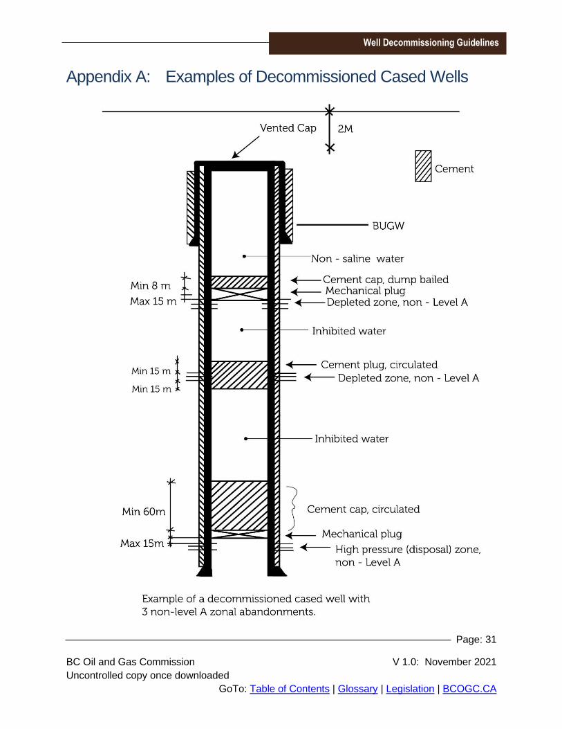
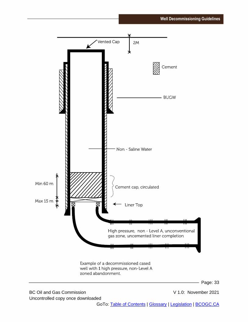
Appendix A: Examples of Decommissioned Cased Wells

Page: 32
BC Oil and Gas Commission V 1.0: November 2021
Uncontrolled copy once downloaded
GoTo: Table of Contents | Glossary | Legislation | BCOGC.CA
Well Decommissioning Guidelines
Page: 33
BC Oil and Gas Commission V 1.0: November 2021
Uncontrolled copy once downloaded
GoTo: Table of Contents | Glossary | Legislation | BCOGC.CA
Well Decommissioning Guidelines

Page: 34
BC Oil and Gas Commission V 1.0: November 2021
Uncontrolled copy once downloaded
GoTo: Table of Contents | Glossary | Legislation | BCOGC.CA
Well Decommissioning Guidelines
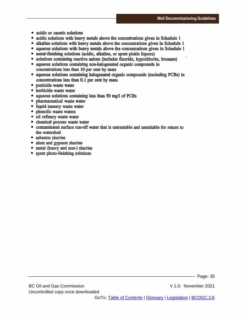
Appendix B: Examples of Disposal Fluids Requiring Level A
Zonal Abandonment
Page: 35
BC Oil and Gas Commission V 1.0: November 2021
Uncontrolled copy once downloaded
GoTo: Table of Contents | Glossary | Legislation | BCOGC.CA
Well Decommissioning Guidelines