well integrity and long-term well performance … · well integrity and long-term well performance...
TRANSCRIPT
Well Integrity and Long-Term Well Performance Assessment
(Insights from work on CO2 Sequestration)
Bill Carey
Earth & Environmental Sciences Division Los Alamos National Laboratory
Los Alamos, NM USA

How Is Wellbore Integrity Achieved? • Operational measures
– Adequate weight drilling mud
– Monitoring pressure for gas intrusion (“gas kick”)
– Blowout preventers • Design measures
– Steel – Portland cement
• Guidelines: API HF1 (hydraulic fracturing),
www.theoildrum.com
Production design
Abandonment
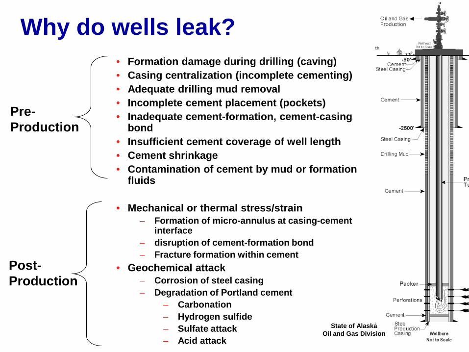
Why do wells leak? • Formation damage during drilling (caving) • Casing centralization (incomplete cementing) • Adequate drilling mud removal • Incomplete cement placement (pockets) • Inadequate cement-formation, cement-casing
bond • Insufficient cement coverage of well length • Cement shrinkage • Contamination of cement by mud or formation
fluids
• Mechanical or thermal stress/strain – Formation of micro-annulus at casing-cement
interface – disruption of cement-formation bond – Fracture formation within cement
• Geochemical attack – Corrosion of steel casing – Degradation of Portland cement
– Carbonation – Hydrogen sulfide – Sulfate attack – Acid attack
Pre- Production
Post-Production
State of Alaska Oil and Gas Division
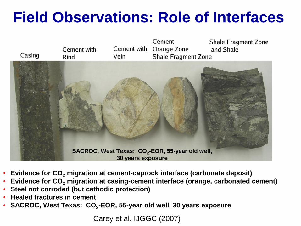
Field Observations: Role of Interfaces
• Evidence for CO2 migration at cement-caprock interface (carbonate deposit) • Evidence for CO2 migration at casing-cement interface (orange, carbonated cement) • Steel not corroded (but cathodic protection) • Healed fractures in cement • SACROC, West Texas: CO2-EOR, 55-year old well, 30 years exposure
Carey et al. IJGGC (2007)
SACROC, West Texas: CO2-EOR, 55-year old well, 30 years exposure
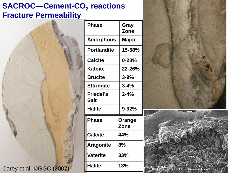
SACROC—Cement-CO2 reactions Fracture Permeability
Phase Orange Zone
Calcite 44%
Aragonite 8%
Vaterite 33%
Halite 13%
Phase Gray Zone
Amorphous Major
Portlandite 15-58%
Calcite 0-28% Katoite 22-26% Brucite 3-9% Ettringite 3-4% Friedel’s Salt
2-4%
Halite 9-32%
Carey et al. IJGGC (2007)

Simulation of SACROC: Accurate account of cement mineralogy
30 year Result Carey and Lichtner (2007)
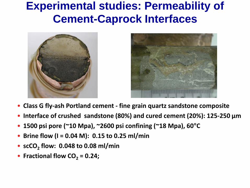
Experimental studies: Permeability of Cement-Caprock Interfaces
• Class G fly-ash Portland cement - fine grain quartz sandstone composite
• Interface of crushed sandstone (80%) and cured cement (20%): 125-250 µm
• 1500 psi pore (~10 Mpa), ~2600 psi confining (~18 Mpa), 60°C • Brine flow (I = 0.04 M): 0.15 to 0.25 ml/min
• scCO2 flow: 0.048 to 0.08 ml/min
• Fractional flow CO2 = 0.24;
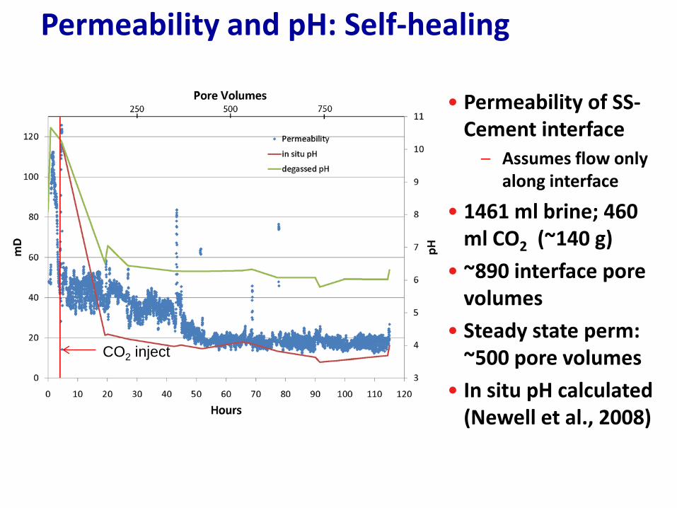
Permeability and pH: Self-healing
• Permeability of SS-Cement interface
– Assumes flow only along interface
• 1461 ml brine; 460 ml CO2 (~140 g)
• ~890 interface pore volumes
• Steady state perm: ~500 pore volumes
• In situ pH calculated (Newell et al., 2008)
CO2 inject
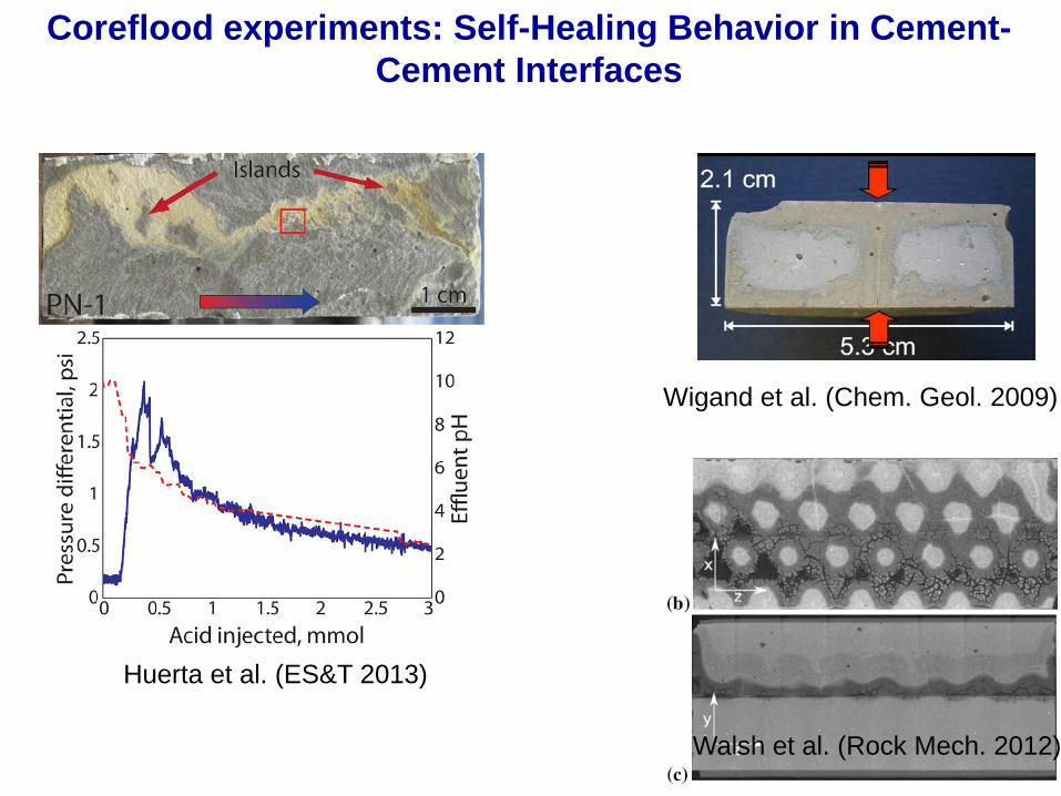
Coreflood experiments: Self-Healing Behavior in Cement-Cement Interfaces
Huerta et al. (ES&T 2013)
Wigand et al. (Chem. Geol. 2009)
Walsh et al. (Rock Mech. 2012)
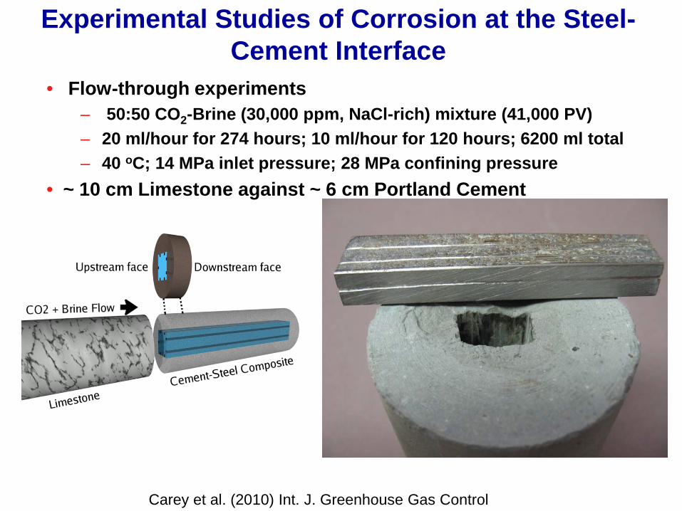
Experimental Studies of Corrosion at the Steel-Cement Interface
• Flow-through experiments – 50:50 CO2-Brine (30,000 ppm, NaCl-rich) mixture (41,000 PV) – 20 ml/hour for 274 hours; 10 ml/hour for 120 hours; 6200 ml total – 40 oC; 14 MPa inlet pressure; 28 MPa confining pressure
• ~ 10 cm Limestone against ~ 6 cm Portland Cement
Carey et al. (2010) Int. J. Greenhouse Gas Control
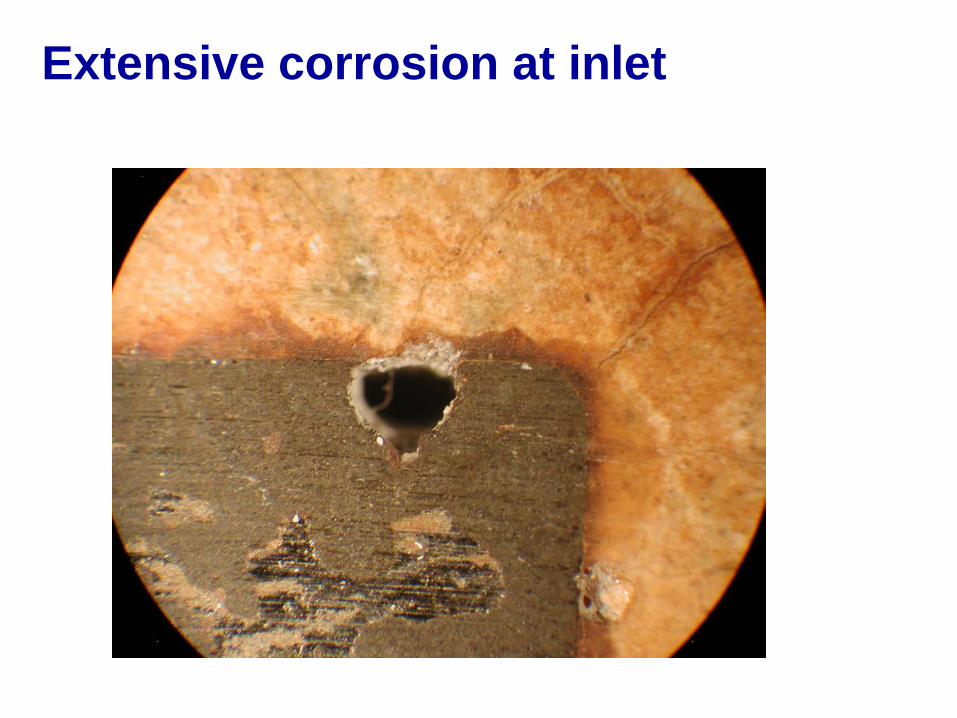
Extensive corrosion at inlet
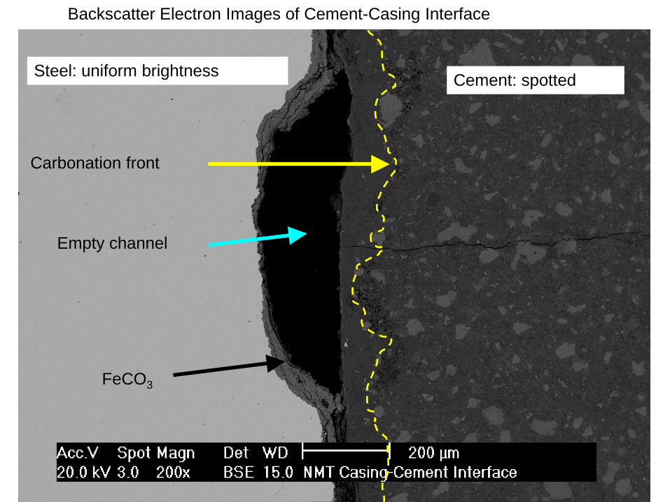
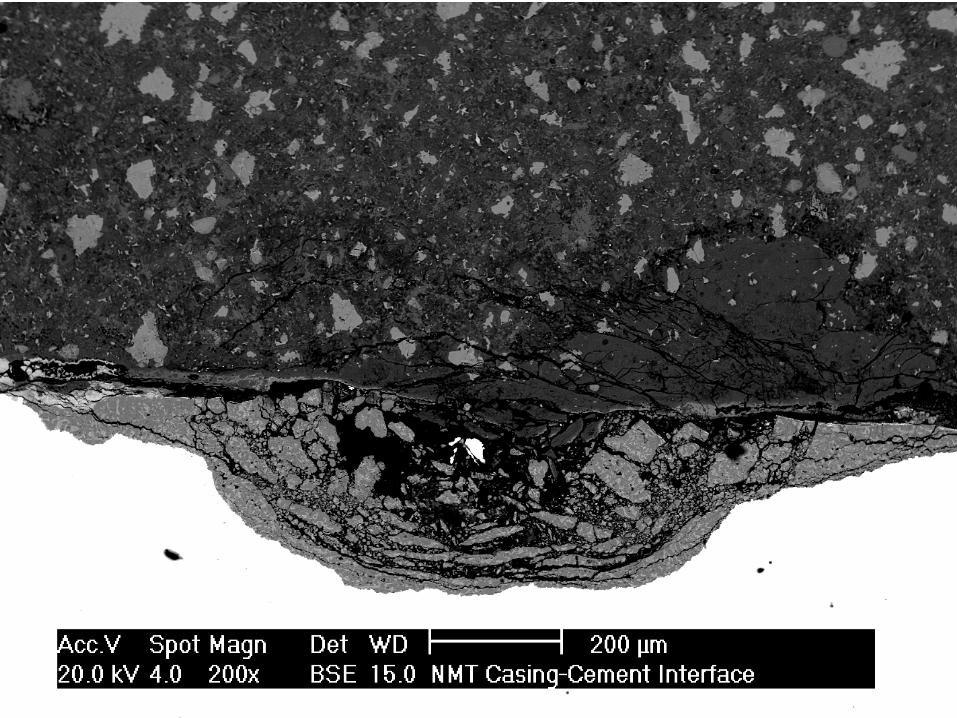
Steel: uniform brightness Cement: spotted
Backscatter Electron Images of Cement-Casing Interface
FeCO3
Empty channel
Carbonation front
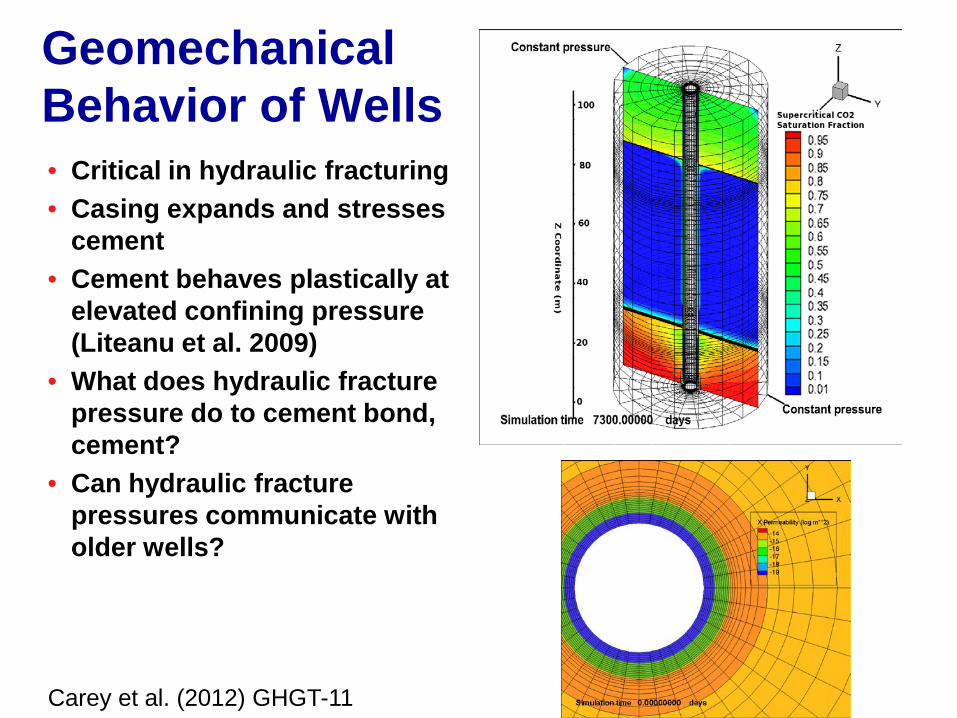
Geomechanical Behavior of Wells • Critical in hydraulic fracturing • Casing expands and stresses
cement • Cement behaves plastically at
elevated confining pressure (Liteanu et al. 2009)
• What does hydraulic fracture pressure do to cement bond, cement?
• Can hydraulic fracture pressures communicate with older wells?
Carey et al. (2012) GHGT-11

Short-Term Versus Long-Term Risk
• Wells are an important part of project risk at early stages
• Late-stage risk is assumed to decrease • What happens to the wellbore over long times?

Conclusions • Wellbore systems are susceptible to flow at
interfaces (cement-steel, cement-caprock, cement fractures)
• Experiments and field observations have demonstrated some degree of self-limiting permeability at interfaces (at least with CO2; Carey, Huerta, Walsh et al.)
• Cement deforms plastically at elevated depths and its geomechanical behavior is critical to assessing potential damage
• Steel response to hydraulic pressure key to assessing damage to isolation
• Coupled mechanical and hydrologic field observations, experiments and models will help resolve threats to zonal isolation
Future Work
• What are the limits (in terms of flow-rate) of self-healing behavior?
• Does carbonated cement protect steel? • What are the hydrologic and mechanical
consequences of cement carbonation? • Are special formulations of cement and
stainless steel necessary in CO2 sequestration projects?
• Coupled mechanical and chemical experiments and models are needed
Acknowledgements
• Department of Energy—Fossil Energy program
• CO2 Capture Project • Colleagues:
– Dennis Newell, Jiabin Han, Barbara Kutchko, Walter Crow, George Guthrie, Rajesh Pawar, Peter Lichtner