west bay sanitary district ssmp 5 year update/audit report · west bay sanitary district ssmp 5...
TRANSCRIPT

July 13,2017 AMConsulting P a g e | 1
Technical Memorandum AMConsulting
West Bay Sanitary District SSMP 5 Year Update/Audit Report
Prepared for: John Simonetti, RCC West Bay Sanitary District
Prepared by: Andy Morrison, Principal AMConsulting
Date: July 13, 2017
Project Scope
AMConsulting was contracted by West Bay Sanitary District to perform an audit of the District’s Sewer System Management Plan (SSMP). The audit process included reviewing the District’s SSMP and various related documents such as the Change Logs, several past SSMP Audits, the Pre-Inspection Questionnaire, the Overflow Emergency Response Plan (OERP), Standard Operation Procedures, SSO Records, and the Asset Inventory. Additionally, the audit process included conducting on-site interactive meetings with staff; visiting all 11 pump stations, observing field crews, performing a gap analysis, and creating a draft and final report. SSMP Audit Analysis
The SSMP Audit Analysis (Attachment A) compares the Elements of the District’s SSMP
to the Statewide General Waste Discharge Requirements (GWDR) Order No. 2006-003-
DWQ and the San Francisco Bay Regional Water Quality Control Board (RWQCB) SSMP
Requirements. The analysis evaluates each element and determines the effectiveness
and compliance.
Summary of Findings
The SSMP was found to be compliant and effective in all of the elements, except a part
of 6.7.2 specifically to “require contractors to be appropriately trained”. All other elements
of the SSMP were found to compliant and effective, as shown in the SSMP Audit Analysis.
The District is being well managed and maintained, as indicated by its improved SSO
Performance. There are some areas of improvement that have been identified and
proposed strategies to address them below.
Strategies That are Working Well
1. Standardization of the pump stations was a very smart strategy implemented in
the past that has made maintaining them much easier, including having
standardized replacement parts in inventory. Continuing this strategy in the future
would be wise.

July 13,2017 AMConsulting P a g e | 2
2. Performing Condition Assessments (PACP) of every sewer main has been a key
strategy in the reduction of SSOs over the years. Updating the PACP score as
defects are corrected, has also been effective in keeping the Sewer Main Asset
Inventory up to date. Continually updating the PACP scores to every segment of
pipe on a periodic basis will be a key strategy in finding future problems/defects
before they result in failure.
3. Emergency preparedness is taken seriously at the District. Periodic Drills are
conducted using the Districts bypass equipment. The District is a member of CAL-
WARN and has trained staff on the SEMS/NIMS system, in addition they have
emergency supplies on hand to continue operations in the event of a disaster.
4. Post SSO Failure Causal Analysis is something that the District takes seriously
and performs well. Besides televising to determine cause and reviewing history to
choose the correct solution, key management people review every SSO event and
the follow-up actions taken to better ensure that there is no recurrence.
5. The long-term reduction of SSOs has been the result of some very significant
changes in system wide operations and management. Some examples of this
include System Wide TV/PACP, FOG Source Control, Aggressive Preventive
Maintenance, and an Integrated Root Control Program.
Areas for Improvement
1. SSO records on site and in Lucity contained some dissimilar information than what
is on some of the CIWQS SSO Reports reviewed. All 3 of these documents
(CIWQS SSO Report and Attachments, Lucity Work Orders and Service Requests,
and Hard Copies of SSO Field Reports and supporting documentation) should be
reviewed to ensure that there are no discrepancies, before certifying a report in
CIWQS.
2. There is a significant lack of details and specificity on the correct way to accomplish
work. This can be accomplished by having detailed Standardized Operating
Procedures, Checklists, and Competency Assessments.
3. The CMMS (Lucity) is not being used to its full potential.
a. Pump Stations are not being managed in Lucity.
i. The Asset Register for Pump Stations in Lucity is not populated.
ii. The various components (pumps, generators, control, and
appurtenances) are not listed as sub-assets (components) of the
pump stations in Lucity

July 13,2017 AMConsulting P a g e | 3
iii. Condition Assessments are not populated for concrete, metal, or
other components in Lucity for pump stations.
b. Not all activities are being tracked with costs being tied to the specific
assets.
c. Field Crews could be using a mapping software to access Lucity in the field
to complete their work and look up history of assets; similar to how West
Valley Sanitation District has been doing successfully for some time.
4. Contingency plans to by-pass the pump stations lack the details of the specific
steps to successfully by-pass the pump stations.
Findings from Pump Station Visits
All of the Pump Stations appeared to be well maintained and in working order. My
observations for each station are in a separate report.
Recommendations
1. Change practice on documenting SSO events and follow up.
a. Compare and amend the current WBSD Call Out Report to include several
items from Attachment C - Start Time Determination Form. The current
practice of simply adding 15 minutes to the notification time may not
sufficiently meet the test of reasonableness, as outlined by the State Water
Board Office of Enforcement (the State). These additional factors should be
used and documented on a form similar to the one described in Attachment
C. Capturing these details on every SSO event, will document how the start
time was determined and answer the question the State will eventually ask.
b. Use a more detailed Volume Determination Worksheet Form as described
in Attachment D. Using forms such as these will capture how the volumes
entered into CIWQS were derived and answer the questions that the State
will eventually ask.
c. Since the State is starting to question the use of pictures of manholes
overflowing that are different than yours, discontinue the use of San Diego’s
pictures of estimating flow rate. Unless you have identical manholes in size,
weight, and pick/vent hole configuration, they will not be accurate. Consider
taking pictures of your own manhole covers overflowing at various rates.
This can be accomplished by using Union Sanitary District’s SSO simulator
with your manhole covers installed. See Attachment F for examples on how
different the appearance can be from one type of manhole cover to another.

July 13,2017 AMConsulting P a g e | 4
d. Amend Section 8 of the OERP to include a process to ensure that the details
match on CIWQS, the SSO Binder, and Lucity. Ideally, this should be done
before ‘Submitting a Draft’ in CIWQS, and certainly should be done before
‘Certifying’ any SSO Report on CIWQS.
2. Make improvements to enhance the training program.
a. Standard Operating Procedures (SOPs) need to be updated or created to
contain more specifics on steps required to complete the various tasks
associated with work, including pictures identifying the parts of the specific
equipment, part, control panel or activity being described similar to the
Samples in Attachment E. Further, SOPs should capture the correct ways
to perform tasks i.e. (EXAMPLE - …..Set your counter to zero before
proceeding. Never exceed the max pressure of the hose, labels, or what is
spelled out on the work order. When cleaning, use a minimum of 1,500 PSI
and a maximum of 4’ per second rate of retrieval, unless otherwise stated
on the work order. Always remove debris at the manhole and never send it
downstream into the next line. …..). Once an SOP is developed or updated,
staff should be trained on the new SOP.
b. Competency Assessments should be developed that are based on
objective standards whenever possible, such as detailed SOPs, Operator’s
manuals, regulations etc. Currently, the basis for determining whether or
not a new employee is ‘trained’ is the use of a checklist with a sign off of an
experience employee such as a Field Supervisor or a Management
employee. This is done based on their individual experience, knowledge,
and opinion, which will vary from individual to individual. The basis for the
assessments and sign-off should be based on the new and improved SOPs.
The assessments should involve the employee being assessed answering
pre-determined specific questions of the equipment, tasks, and hazards,
and the employee demonstrating the proper way to complete
predetermined tasks. Competency Assessments should be conducted after
an employee has been trained and periodically thereafter. Since developing
and implementing this program will take a significant amount of staff time
and resources, the District should focus on the tasks and activities that have
the highest consequence of error first.
3. Use Lucity to better manage your assets and track all activities.
a. Sewer Mains are currently populated in the system and most associated
activities are being tracked, however the Aging Work Order Report includes
many open Work Orders from 2012 and none of the incomplete Spot
Repairs, Trenchless Repairs, or CIP repairs are in the list. A Work Order

July 13,2017 AMConsulting P a g e | 5
should be created for all future work so that the future workload can be
quantified and prioritized, and the costs associated with those repairs can
be tracked to the Asset. Additionally, a Post Repair Work Order should be
created to TV the main and update the PACP score. Also, a work order
should be created for all non-scheduled cleaning that is performed.
b. Pump Stations should be populated in Lucity with all of their components
(pumps, generators, panels, telemetry, UPB etc.) associated to the pump
station asset in Lucity. All inspections and activities should be tied to a work
order to the pump station or the specific sub-component. When the work is
complete, all associated costs should be tied to that pump station or
component. Additionally, Condition Assessments of the metal at the station
and the concrete in the wet well should be conducted and the scores/results
captured in Lucity. These assessments should be done as part of the
Annual Inspections and the scores/results updated in Lucity.
c. Non-District Assets such as grinders are not all currently in Lucity. As the
District takes on additional work for other agencies, they should add those
assets in Lucity, clearly identifying them as non-District assets, and create
and complete work orders as they would their own assets, so that they can
better manage them and know exactly how much resources are spent on
maintaining them.
4. Plan to expand the Root Control Program.
a. For the past decade root intrusion has been the primary cause of SSOs. To
further improve SSO performance, the District will have to become even
more aggressive with Root Control. Over time, root intrusion will become an
increasingly more difficult problem to manage. Mechanical removal alone
will become more and more burdensome in the amount of labor hours it will
take to accomplish the work. The best long-term strategy is to add all of the
mains with multiple points of root intrusion to the chemical control program,
which will free up staff time to accomplish other work, as they eventually will
only need to cut the roots every 3 years, instead of every 3 months (12 times
in 3 years). When adding a sewer main to the chemical program, reapply
the chemical after 1 year, then reapply 2 years after 2nd treatment, and then
apply every 3 years after that. This ramped up approach is a proven strategy
to effectively prevent re-growth of roots in sewers. This will be a significant
increase in future budgets.

July 13,2017 AMConsulting P a g e | 6
5. Upgrade the Contingency Plan to include detailed steps needed to by-pass each
pump station.
a. While existing staff responsible for pump stations are quite competent
enough to setup a by-pass for each pump station without written
procedures, the existing Contingency Plans lack the detailed steps needed
to set-up the by-pass. In the event of major disaster such as a very large
earthquake, the District may need to have staff unfamiliar with the station,
contractors, or personnel activated through CAL-WARN set up the by-
passes. In order for those people to accomplish the task, they will need a
detailed Contingency Plan. Where to park the pump, where to connect the
suction hose, where to discharge, which valves to close, which valves to
open, and expected maximum downtime before an SSO occurs should be
documented with photos and a step by step instructions for each station.
Additionally, Village Square PS may not be by-passed with pumps, as
shown, it may be accomplished with a vacuum truck every 2 days, the
updated plan should reflect this as well.
Conclusions
The District has made many substantive changes in the past several years that have
resulted in a much improved SSO performance, achieving their interim goal stated on
page 11 of the WBSD Performance Measures Report, “the interim goal of the District is
to have fewer overflows within Region-2 of the San Francisco Bay Area.”. It will be very
difficult to achieve the long-term goal “to maintain the sewer collection system so that
there are no SSOs’. Of the 5 recommendations, #2 and #4 will likely have the biggest
impact in affecting that outcome, along with continuing the efforts that are working well.
Attachments
A. SSMP Audit Analysis
B. Operational Performance Report – From CIWQS
C. Sample SSO Start Time Determination Form
D. Sample SSO Volume Estimation Form
E. Sample Standard Operating Procedure
F. Examples of Different Types of Manhole Cover at Various Rates of Flow

Attachment A West Bay Sanitary District SSMP Audit Analysis
July 13,2017 AMConsulting P a g e | 7
Required Element
RWQCB Requirements (summarized)
SWRCB Requirements (summarized)
Assessment
Goals
1 Develop goals to manage, operate, and maintain all parts of the collection system. Address the provision of adequate capacity, the reduction of SSO frequency, and the mitigation of SSO impacts.
i Develop goals to properly manage, operate, and maintain all parts of the collection system in order to prevent SSOs and mitigate any SSOs that occur.
Y
Y
The District’s goals listed in Section 1 and the programs that they use to accomplish these goals meet the requirements.
Organization
2 Identify staff (names and phone numbers) responsible for implementing measures outlined in the SSMP, including management, administration, and maintenance positions. Identify chain of communication for reporting and responding to SSOs.
ii Identify the Legally Responsible Representative(s). Identify the names and phone numbers for management, administrative, and maintenance positions responsible for implementing specific measures in the SSMP. Include lines of authority as shown on an organization chart or similar document, with a narrative. Identify the Chain of Communication for reporting SSOs, from receipt of information, including the person responsible for reporting SSOs to the proper agencies.
Y
Y
The District has comprehensively met these requirements. A note of caution, this particular portion of the SSMP contains details that become inaccurate whenever there are staffing changes. As those changes occur, those changes should be made in this section and then noted in the Update Log.
Overflow Emergency Response Plan
3 Develop an Overflow Emergency Response Plan that provides procedures for SSO notification, response, reporting, and impact mitigation.
vi Develop and implement an Overflow Emergency Response Plan that identifies measures to protect the public health and the environment. And must include, proper and prompt notification procedures, a program to ensure appropriate response to all overflows, procedures to ensure staff and contractors are aware of and follow the plan and are properly trained, procedures to address emergency operations, and a program to ensure all reasonable steps are taken to contain wastewater and prevent discharge to water of the US and minimize impacts, including monitoring
Y
Y
The District OERP is complete, comprehensive, and meets and exceeds these requirements. Some typos and other editorial changes were identified on the Stand-Alone Document hard copy and given to the District’s Regulatory Compliance Coordinator. When the editorial changes are made, Appendix 3A should be amended and the change noted on the Update
RW
QC
B N
o.
SW
RC
B N
o.
Co
mp
lian
t
Eff
ecti
ve

Attachment A West Bay Sanitary District SSMP Audit Analysis
July 13,2017 AMConsulting P a g e | 8
Log or done at this 5-year re-certification.
Fats, Oil, and Grease (FOG) Control Program
4 Determine if FOG Control Program is needed and develop A FOG Control Program if needed.
vii Determine if FOG Control Program is needed and develop A FOG Control Program if needed. The Program shall include the following as appropriate;
• Plan and schedule for education, outreach, a proper disposal
• Plan and schedule for proper disposal of FOG
• Legal Authority to prohibit FOG discharges
• Grease Removal Devices design standards, installation, maintenance, BMPs, record keeping, and reporting requirements
• Identification of sewers subject to FOG blockages and the establishment of cleaning schedules
• Development and implementation of for source control measures
Y
Y
The District has a very comprehensive and effective FOG Control Program that meets all of these requirements. The efforts to control FOG over the past several years have resulted in a dramatic reduction in SSOs cause by FOG. There were only 2 FOG caused SSOs in the past 5 years (0.4/yr.), compared to 28 in the previous 5 years (5.6/yr.) Outstanding!
Legal Authority
5 Have legal authority to control I/I from satellite collection systems and laterals; require proper design, construction, installation, testing, and inspection of new and rehabilitated sewers and laterals; and enforce violations.
Iii Possess legal authority to;
• Prevent illicit discharges including I/I, storm water, chemical dumping, unauthorized debris and cut roots etc.
• Require sewers and connections be properly designed
• Ensure access for maintenance, inspection, or repairs for portion of lateral owned by agency (N/A to WBSD)
• Limit the discharges of FOG and other debris that can cause blockages; and
• Enforce any violations
Y
Y
The District has all of the Ordinances in place to meet all of these requirements, including enforcement.
Measures and Activities
6 1. Maintain current maps of the collection system
2. Allocate adequate resources for Operation and Maintenance
3. Demonstrate that prioritized maintenance activities are performed
iv 1. Maintain up to date maps of all of the collections, showing all appurtenances
2. No requirement 3. Describe and document preventive
O&M activities, including problem areas. Have a system to document activities
Y
Y
Y
Y
1. The District has systems in place to meet the Map requirements and has up to date maps
2. The District has adequate funding for its current operations and

Attachment A West Bay Sanitary District SSMP Audit Analysis
July 13,2017 AMConsulting P a g e | 9
4. Identify and prioritize structural deficiencies and implement short-term and long-term plans to address them
5. Demonstrate that contingency equipment is provided to handle emergencies and spare parts are on hand
6. Provide Training on a regular basis for staff
7. Implement an outreach program to educate contractors and plumbers
4. Develop R&R plan to identify and prioritize system deficiencies and implement short-term and long-term plans to address them. Program should include regular visual and TV inspections of manholes and pipes, and a system to rank condition of pipes. Plan should include a capital improvement plan that addresses proper management and protection of the assets, including time schedule for implementing plans and obtaining funds needed
5. Provide equipment and replacement part inventories, including critical parts
6. Provide training on a regular basis for staff in sanitary sewer system operations and maintenance, and require contractors to be appropriately trained
7. No requirement
Y
Y
Y
N
Y
Y
Y
Y
N
Y
future CIP. In the near future, the District will likely have a need to significantly increase the Chemical Root Control Program.
3. The District has a comprehensive PMP that addresses the elements of this requirement.
4. The District’s PACP and CIP programs are working well to meet this requirement
5. The District has plenty of spare parts and equipment, as well as by-pass pumping capabilities. This requirement is met.
6. It is evident that the staff is trained and able to do their jobs, the absence of detailed SOPs make it difficult to verify that training is consistently conveyed. Hands-on drills are conducted to ensure readiness to emergency situations. It is not, however, identified in the SSMP 6.7.2 how “contractors are required to be appropriately trained”
7. The efforts outlined in the SSMP meet this requirement
Design and Construction Standards
7 Have design and construction standards and specifications for the installation of new sewer systems and the R&R of existing sewer systems. Have procedures and standards for inspection and testing of new sewers, pump stations, and other appurtenances, as well as R&R projects
V Have design and construction standards and specifications for the installation of new sewer systems, pump stations, and other appurtenances and the R&R of existing sewer systems. Have procedures and standards for inspection and testing the installation of new sewers, pumps, and other appurtenances, and for R&R projects
Y
Y
The District’s Standards and Specifications and work practices meet this requirement

Attachment A West Bay Sanitary District SSMP Audit Analysis
July 13,2017 AMConsulting P a g e | 10
Capacity Management
8 Have a process to establish current and future requirements of the collection system
viii Evaluate hydraulic deficiencies and identify peak flows and conditions causing overflows, and identify sources that contribute to peak flows. Establish Design Criteria.
Y
Y
The District does not have problems with capacity that result in SSOs. Regardless, they do study their flows and have factored that into their long-term planning. The SSMP references “a consistent design storm” and “the applied design storm”, but it does not spell out what the design storm criteria is or where it is located, as it should. AMC was able to locate the design storm of 10-year interval and 6-hour duration in their Master Plan. AMC recommends indicating, in the SSMP, where the design criteria are located or simply state the criteria in the SSMP.
Monitoring, Measurement, and Program Modifications
9 Monitor the effectiveness of the SSMP elements and update and modify the elements to keep the current, accurate, and available as appropriate.
ix Maintain relevant information that can be used to establish and prioritize SSMP activities. Monitor and measure the effectiveness of each element of the SSMP. Assess the success of the PMP. Update program elements as appropriate, Identify and illustrate SSO trends, including frequency, location, and volume.
Y
Y
The District does an excellent job on meeting all of the elements of these requirements.
SSMP Audits
10 Conduct an annual audit of the SSMP that includes deficiencies and steps to correct them, appropriate to size of system and number of overflows. Submit report of annual audit.
x Conduct periodic internal audits, appropriate to the size of the system and the number of SSOs, every 2 years and keep report on file. The audit shall focus on evaluating the effectiveness of the SSMP and compliance with the SSMP, including identifying deficiencies and steps to correct them,
Y
Y
The District has been conducting annual audits internally, which meets both the RWQCB and SWRCB requirements. Additionally, the District has elected to hire consultants to conduct
Attachment A West Bay Sanitary District SSMP Audit Analysis
July 13,2017 AMConsulting P a g e | 11
Independent Audits as part of the 5-year SSMP Re-Certification process, which clearly exceeds these requirements.
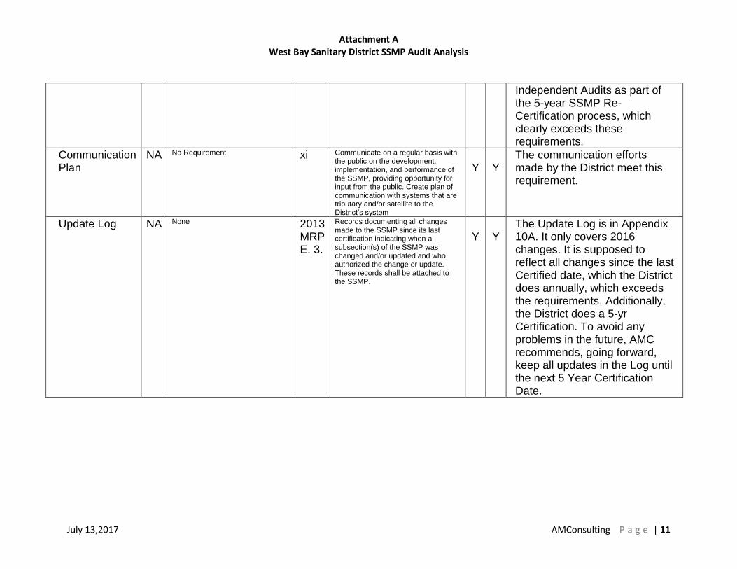
Communication Plan
NA No Requirement xi Communicate on a regular basis with the public on the development, implementation, and performance of the SSMP, providing opportunity for input from the public. Create plan of communication with systems that are tributary and/or satellite to the District’s system
Y
Y
The communication efforts made by the District meet this requirement.
Update Log
NA None 2013 MRP E. 3.
Records documenting all changes made to the SSMP since its last certification indicating when a subsection(s) of the SSMP was changed and/or updated and who authorized the change or update. These records shall be attached to the SSMP.
Y
Y
The Update Log is in Appendix 10A. It only covers 2016 changes. It is supposed to reflect all changes since the last Certified date, which the District does annually, which exceeds the requirements. Additionally, the District does a 5-yr Certification. To avoid any problems in the future, AMC recommends, going forward, keep all updates in the Log until the next 5 Year Certification Date.

Attachment B Operational Performance Report – From CIWQS
July 13,2017 AMConsulting P a g e | 12
As stated on page 11 of the WBSD Performance Measure Report, “the District’s goal is
to maintain the sewer collection system so that there are no SSOs. Especially important
is to prevent overflows that reach a creek, tributary-drainage channel or other body of
water, all of which are considered “Category 1 SSOs”. While the overall goal is to
prevent all overflows, the interim goal of the District is to have fewer overflows within
Region-2 of the San Francisco Bay Area. Region-2 has approximately 115 participating
Agencies and that data is more reflective of West Bay Sanitary Districts Age, terrain and
geological characteristics.” Using CIWQS data, it is clear to see that the District is
meeting the interim goal. WBSD’s SSO performance is far better than the average of
other agencies in the State and the Region, as shown in the graphs on the following
pages.

Attachment B Operational Performance Report – From CIWQS
July 13,2017 AMConsulting P a g e | 13

Attachment B Operational Performance Report – From CIWQS
July 13,2017 AMConsulting P a g e | 14
+

Attachment B Operational Performance Report – From CIWQS
July 13,2017 AMConsulting P a g e | 15

Attachment B Operational Performance Report – From CIWQS
July 13,2017 AMConsulting P a g e | 16

Attachment B Operational Performance Report – From CIWQS
July 13,2017 AMConsulting P a g e | 17

Attachment B Operational Performance Report – From CIWQS
July 13,2017 AMConsulting P a g e | 18

Attachment B Operational Performance Report – From CIWQS
July 13,2017 AMConsulting P a g e | 19

Attachment C Sample SSO Start Time Determination Form
July 13,2017 AMConsulting P a g e | 20
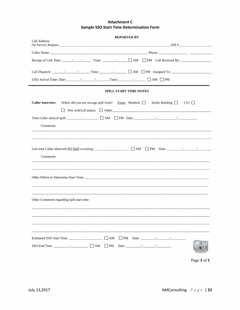
Determining the start time of an SSO can be very challenging. However, documenting
how the determination was made is relatively easy. It can be done as stand-alone
document, but making it part of the field documentation form makes it less likely to be
forgotten and easier to keep with the SSO Report file. On the next page, you will find a
sample of how start time determination can be documented.
Attachment C Sample SSO Start Time Determination Form
July 13,2017 AMConsulting P a g e | 21
(6 Page Document) USD SSO RESPONSE - FIELD DOCUMENTATION
Page 1 of 1
REPORTED BY
Call Address:
On Service Request __________________________________________________________________ (SR #____________________)
Caller Name: __________________________________________________________ Phone: _________________ ______________
Receipt of Call: Date: ______/_____/_____ Time: _______:_______ AM PM Call Received By: __________________
Call Dispatch: _______/_______/_______ Time:________:________ AM PM Assigned To: ________________________
USD Arrival Time: Date: ________/________/________ Time:_________:_______ AM PM
SPILL START TIME NOTES
Caller Interview: Where did you see sewage spill from? From: Manhole Inside Building C/O
Wet well/Lift station Other___________________________________________________________
Time Caller noticed spill: _________:_________ AM PM Date:_____________/____________/____________
Comments:
___________________________________________________________________________________________________________
___________________________________________________________________________________________________________
Last time Caller observed NO Spill occurring: __________:__________ AM PM Date: _________/________/________
Comments:
__________________________________________________________________________________________________________
__________________________________________________________________________________________________________
Other Efforts to Determine Start Time: __________________________________________________________________________
_________________________________________________________________________________________________________
_________________________________________________________________________________________________________
Other Comments regarding spill start time:
__________________________________________________________________________________________________________
__________________________________________________________________________________________________________
__________________________________________________________________________________________________________
__________________________________________________________________________________________________________
Estimated SSO Start Time __________:__________ AM PM Date: _________/________/_________
SSO End Time __________:__________ AM PM Date: _________/________/_________

Attachment D Sample SSO Volume Estimation Form
July 13,2017 AMConsulting P a g e | 22
The District currently has forms to capture some of the calculations used in determining
volumes reported in CIWQS. There are more comprehensive forms that can be used.
On the following pages, you will see some samples of some forms that can be
incorporated into your forms
See pages 2 and 3 of the attached PDF “Sample – SSO Response Field
Documentation Form Sept 2013” and the attached PDF “Sample – SSO Volume
Estimate by Area Work Sheet”

Attachment D Sample SSO Volume Estimation Form
July 13,2017 AMConsulting P a g e | 23
SPILL VOLUME WORKSHEET
The purpose of this worksheet is to capture the data and method(s) used in estimating the volume of an SSO. Since there
are many variables and often unknown values involved, this calculation is just an estimate. Additionally, it is useful to use
more than one method, if possible, to validate your estimate.
The following methods and tools are the approved methods in the SOP CS-103 SSO Response. Check all methods and tools
that you used:
Eyeball Estimate Method
Measured Volume Method
Duration and Flow Rate Method (Account for diurnal flow pattern for long duration)
USD SSO Flow Rate Estimating Tool
Other (explain) i.e.; estimated daily use per capita upstream or meter @ Pump Station.
___________________________________________________________________________________________
_____
___________________________________________________________________________________________________
____
Eyeball Estimate Method- Imagine a bucket(s) or barrel(s) of water tipped over.
Size of bucket(s) or
barrel(s)
How many of this
Size?
Multiplier Total Volume
Estimated
1 gal. water jug X 1
5 gal. bucket X 5
32 gal. trash can X 32
55 gal drum X 55
Total Volume Estimated
Using Eyeball Method

Attachment D Sample SSO Volume Estimation Form
July 13,2017 AMConsulting P a g e | 24
Duration and Flow Rate Method worksheet:
Start Date and Time 1. 1.
End Date and time 2. 2.
Total time elapsed of SSO event (subtract line 1
from line 2. Show time in minutes)
3. 3.
Average flow rate GPM (account for diurnal
pattern)
4. 4.
Total volume estimate using duration and flow rate
method (Line 3 x Line 4)
5. 5.
Measured Volume Method (this may take several calculation as may have to break down the odd shaped spill to
rectangles, circles, and polygons) It is important when guessing depth to measure, if possible in several locations and use
an average depth. Use the SSO Volume Estimate by Area Work Sheet , if necessary, to sketch the shapes and show your
work.
1. Draw a sketch of the spill SSO Volume Estimate by Area Work Sheet, or use a photo copy of USD block book to
draw on and attach it.
2. Draw shapes and dimensions used on your sketch
3. Use correct formula for various shapes
Rectangle L x W x D
Circle 3.14 x R² x D
Polygons see reference chart Show formula used

Attachment D Sample SSO Volume Estimation Form
July 13,2017 AMConsulting P a g e | 25
SSO Volume by Area Estimation Work Sheet
Page 1
Surface: Asphalt Concrete Dirt Landscape Inside Building Other ____________________
(Draw / Sketch outline of Spill ‘Footprint’ and attach photos)
~~ Breakdown the ‘Footprint’ into Recognizable Shapes and Determine Dimensions of Each Shape ~~ Area #1________________________________________________________________________ % Wet _______ Stain. Depth1_____ Depth2 _____ Depth3 _____ Depth4 _____ Depth5 _____ Depth6 _____ Area #2________________________________________________________________________ % Wet _______
Stain. Depth1_____ Depth2 _____ Depth3 _____ Depth4 _____ Depth5 _____ Depth6 _____ Area #3________________________________________________________________________ % Wet _______ Stain. Depth1_____ Depth2 _____ Depth3 _____ Depth4 _____ Depth5 _____ Depth6 _____ Area #4________________________________________________________________________ % Wet _______ Stain. Depth1_____ Depth2 _____ Depth3 _____ Depth4 _____ Depth5 _____ Depth6 _____ Area #5________________________________________________________________________ % Wet _______
Stain. Depth1_____ Depth2 _____ Depth3 _____ Depth4 _____ Depth5 _____ Depth6 _____ Area #6________________________________________________________________________ % Wet _______ Stain. Depth1_____ Depth2 _____ Depth3 _____ Depth4 _____ Depth5 _____ Depth6 _____

Attachment D Sample SSO Volume Estimation Form
July 13,2017 AMConsulting P a g e | 26
Square Feet: ______________ x % Wet _______ = ____________ Sq/Ft
Ave Depth: ______________ Concrete 0.0026’ Asphalt 0.0013’
Volume: ________________ Cu/Ft
Area #2 Square Feet: ______________ x % Wet _______ = ____________ Sq/Ft
Ave Depth: ______________ Concrete 0.0026’ Asphalt 0.0013’
Volume: ________________ Cu/Ft Area #3 Square Feet: ______________ x % Wet _______ = ____________ Sq/Ft
Ave Depth: ______________ Concrete 0.0026’ Asphalt 0.0013’
Volume: ________________ Cu/Ft Area #4 Square Feet: ______________ x % Wet _______ = ____________ Sq/Ft
Ave Depth: ______________ Concrete 0.0026’ Asphalt 0.0013’
Volume: ________________ Cu/Ft Area #5 Square Feet: ______________ x % Wet _______ = ____________ Sq/Ft
Ave Depth: ______________ Concrete 0.0026’ Asphalt 0.0013’
Volume: ________________ Cu/Ft Area #6 Square Feet: ______________ x % Wet _______ = ____________ Sq/Ft
Ave Depth: ______________ Concrete 0.0026’ Asphalt 0.0013’
Volume: ________________ Cu/Ft
Total Volume: #1 ________, #2 ________, #3 ________, #4 ________, #5 ________, #6 ________ = _________ *cu ft
_________ *cu ft x 7.48 gallons = _____________ gallons Spilled.
Attachment D Sample SSO Volume Estimation Form
July 13,2017 AMConsulting P a g e | 27
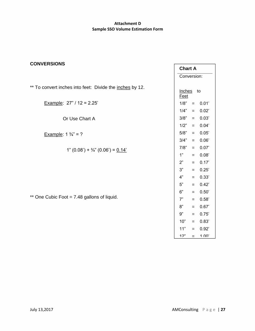
CONVERSIONS
** To convert inches into feet: Divide the inches by 12.
Example: 27” / 12 = 2.25’
Or Use Chart A
Example: 1 ¾” = ?
1” (0.08’) + ¾” (0.06’) = 0.14’
** One Cubic Foot = 7.48 gallons of liquid.
Chart A
Conversion:
Inches to Feet
1/8” = 0.01’
1/4” = 0.02’
3/8” = 0.03’
1/2” = 0.04’
5/8” = 0.05’
3/4” = 0.06’
7/8” = 0.07’
1” = 0.08’
2” = 0.17’
3” = 0.25’
4” = 0.33’
5” = 0.42’
6” = 0.50’
7” = 0.58’
8” = 0.67’
9” = 0.75’
10” = 0.83’
11” = 0.92’
12” = 1.00’

Attachment D Sample SSO Volume Estimation Form
July 13,2017 AMConsulting P a g e | 28
GEOMETRY
For the purposes of this work sheet, the unit of measurement will be in feet for formula examples.
Area is two-dimensional - represented in square feet. (Length x Width)
Volume is three-dimensional - represented in cubic feet. (Length x Width x depth) or
(Diameter Squared) D2 x 0.785 x depth.
A Note about Depth
Wet Stain on a Concrete Surface - For a stain on concrete, use 0.0026’. This number is 1/32” converted to feet. For a stain on asphalt use 0.0013’ (1/64”). These were determined to be a reasonable depth to use on the respective surfaces through a process of trial and error by SPUD staff. A known amount of water (one gallon) was poured onto both asphalt and concrete surfaces. Once the Area was determined as accurately as possible, different depths were used to determine the volume of the wetted footprint until the formula produced a result that (closely) matched the one gallon spilled. 1/32” was the most consistently accurate depth on concrete and 1/64” for asphalt. This process was repeated several times.
Sewage “Ponding” or Contained – Measure actual depth of standing sewage whenever possible. When depth varies, measure several (representative) points, determine the average and use that number in your formula to determine volume.
Area/Volume Formulas
Area is two dimensional and is represented as Square Feet (SQ/FT)
Volume is three dimensional and is represented as Cubic Feet (CU/FT)
One Cubic Foot = 7.48 gallons

Attachment D Sample SSO Volume Estimation Form
July 13,2017 AMConsulting P a g e | 29
AREA/VOLUME OF A RECTANGLE OR SQUARE
Formula: Length x Width x Depth = Volume in Cubic Feet
Depth = 1 ¾”
Length (25’) x Width (12’) x Depth (0.14’)
25’ x 12’ x 0.14’ = 42 Cubic Feet.
Now the Volume in Cubic Feet is known.
There are 7.48 Gallons in one Cubic Foot
So, 42 Cubic Feet x 7.48 gallons/cubic feet = 314 Gallons
1 2 ’
25’
Chart A
Conversion:
Inches to Feet
1/8” = 0.01’
1/4” = 0.02’
3/8” = 0.03’
1/2” = 0.04’
5/8” = 0.05’
3/4” = 0.06’
7/8” = 0.07’
1” = 0.08’
2” = 0.17’
3” = 0.25’
4” = 0.33’
5” = 0.42’
6” = 0.50’
7” = 0.58’
8” = 0.67’
9” = 0.75’
10” = 0.83’
11” = 0.92’
12” = 1.00’

Attachment D Sample SSO Volume Estimation Form
July 13,2017 AMConsulting P a g e | 30
AREA/VOLUME OF A RIGHT TRIANGLE
Base x Height x 0.5 x Depth = Volume in Cubic Feet
Depth = 5/8”
Base (45’) x Height (10’) x 0.5 x Depth (.05’) x 7.48 gallons/cubic foot = 84 gallons
For Isosceles Triangles (two sides are equal lengths), Break it down into two Right Triangles and compute area as you would for the Right Triangle above.
10’
45’
Chart A
Conversion:
Inches to Feet
1/8” = 0.01’
1/4” = 0.02’
3/8” = 0.03’
1/2” = 0.04’
5/8” = 0.05’
3/4” = 0.06’
7/8” = 0.07’
1” = 0.08’
2” = 0.17’
3” = 0.25’
4” = 0.33’
5” = 0.42’
6” = 0.50’
7” = 0.58’
8” = 0.67’
9” = 0.75’
10” = 0.83’
11” = 0.92’
12” = 1.00’

Attachment D Sample SSO Volume Estimation Form
July 13,2017 AMConsulting P a g e | 31
AREA/VOLUME OF A CIRCLE/CYLINDER
Diameter Squared x 0.785 x Depth = Volume in cubic feet.
Diameter = Any straight line segment that passes through
the center of a circle.
For our purposes, it is the measurement across the widest
part of a circle.
D2 x 0.785 x depth = Volume in cubic feet
Example:
27’ x 27’ x 0.785 x 0.03 = 17.17 cubic feet
17.17 cubic feet x 7.48 gallons/cubic feet = 128 gallons
Diameter = 27’ Depth = 3/8”
Chart - A
Conversion:
Inches to Feet
1/8” = 0.01’
1/4” = 0.02’
3/8” = 0.03’
1/2” = 0.04’
5/8” = 0.05’
3/4” = 0.06’
7/8” = 0.07’
1” = 0.08’
2” = 0.17’
3” = 0.25’
4” = 0.33’
5” = 0.42’
6” = 0.50’
7” = 0.58’
8” = 0.67’
9” = 0.75’
10” = 0.83’
11” = 0.92’
12” = 1.00’
D2 x 0.785 x d

Attachment D Sample SSO Volume Estimation Form
July 13,2017 AMConsulting P a g e | 32
Find the geometric shapes within the shape. If this was the shape of your spill, break it down, as best you can, with the shapes we know.
1. Determine the volumes of each shape.
In this example, after the volume of the circle is determined, multiply it by 55% (+/-) so that the overlap area won’t be counted twice.
2. Add all the volumes to determine total spill volume.
Attachment D Sample SSO Volume Estimation Form
July 13,2017 AMConsulting P a g e | 33
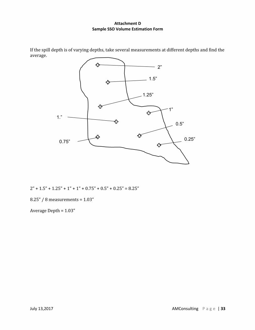
If the spill depth is of varying depths, take several measurements at different depths and find the average. 2” + 1.5” + 1.25” + 1” + 1” + 0.75” + 0.5” + 0.25” = 8.25” 8.25” / 8 measurements = 1.03” Average Depth = 1.03”
2”
1.5”
1.25”
1”
0.5”
0.25” 0.75”
1.”

Attachment D Sample SSO Volume Estimation Form
July 13,2017 AMConsulting P a g e | 34
2” + 1.5” + 1.25” + 3” + 5” + 1.25” = 14.0” 14.0” / 6 measurements = 2.33” Average Depth = 2.33” (0.194’)
2”
1.5”
1.25”
3”
5”
1.25”
Step 1
If the spill affects a dry, unimproved area such as a field or dirt parking lot, determine the Area of the wetted ground in the same manner as you would on a hard surface. Using a round-point shovel, dig down into the soil until you find dry soil. Do this in several locations within the wetted area and measure the depth of the wet soil. Average the measurement/thickness of the wet soil and determine the average depth of the wet soil.
Step 2
Take a Test Sample
( See Next Page)
NOTE: This can be used in a (Dry) dirt or grassy area that is not regularly irrigated like a field or a dirt parking lot.
Wet weather would make this method ineffective.
EXAMPLE:
If the Area of the spill was determined to be 128 Sq/Ft and the average depth of the wet soil is 2.33 inches:
128 Sq/Ft x 0.194’ = 24.83 Cu/Ft
24.83 Cu/Ft x 7.48 Gals/Cu/Ft = 185.74 gallons
185.74 x 18% = 33 Gallons (water in soil)

Attachment E Sample Standard Operating Procedure
July 13,2017 AMConsulting P a g e | 35
Standard Operating Procedures should be specific enough and detailed enough that
they identify hazards associated with various tasks, capture the steps necessary to
complete the various tasks and activities safely and effectively, and can be used to
assess whether or not an employee has the necessary KSAs and is performing the job
correctly. See attached PDF “Sample SOP-CS100 Vactor Truck Operations” and
“Sample SOP-CS100-1 Sewer Line Cleaning and Use of Special Tools”. These are
samples only. The District would need to develop SOPs specific to their equipment and
operations.

Attachment F
Examples of Different Types of Manhole Cover at Various Rates of Flow
July 13,2017 AMConsulting P a g e | 36
Using San Diego’s Pictures instead of using pictures of WBSD manholes could result in
wildly inaccurate estimates of flow rates, resulting in inaccurate volume estimates. In the
examples below, each group of 4 manholes are showing exactly the same rate of flow in
GPM out very different lids (in size, weight & number of holes). The differences are very
notable.

Attachment F
Examples of Different Types of Manhole Cover at Various Rates of Flow
July 13,2017 AMConsulting P a g e | 37

Attachment F
Examples of Different Types of Manhole Cover at Various Rates of Flow
July 13,2017 AMConsulting P a g e | 38

Attachment F
Examples of Different Types of Manhole Cover at Various Rates of Flow
July 13,2017 AMConsulting P a g e | 39

Observations from site visits to all of the Pump Stations on 5/16/17
1. Village Square had a slight odor that can be detected as you approach the
station. If this ever becomes a problem with the public, a small charcoal filter
used on air vacuumed out of wet well should resolve it. The Contingency Plan
shows a pump and a connection point, but does not even mention the existing
alternative method of using a vacuum truck to draw down the wet well.
2. Sausal Vista was very clean.
3. Los Trancos fence did not have any barbed wire or non-climbable features.
4. Stowe Lane dry well needed to be cleaned. There should be sign stating “Before
entering dry well, turn on fan and ensure that there is a person on top”. The
brackets in the wet well were severely corroded.
5. Illinois had minor corrosion in the valve pit.
6. University had minor corrosion on the pipe support, minor root intrusion in the
wet well, and needed fall protection around the valve pit opening.
7. Willow had a very nice fence for a pump station. I observed minor corrosion on
the U-strut on the deck and the fuel tank, severe corrosion on metal in the wet
well, and minor/moderate corrosion on metal in the valve pit. Additionally, the
valve pit opening needed fall protection.
8. Menlo Industrial Park looked good except, whoever trimmed the bush/hedge
outside of the station damaged the razor wire.
9. Hamilton-Henderson had minor/moderate corrosion on the deck and needed fall
protection around the valve box opening.
10. Vintage Oak #1 had severe corrosion on the conduit ends and needed fall
protection around the valve pit. No signs were in place identifying the facility as a
WBSD facility with a 24-hour contact phone number.
11. Vintage Oak #2 had minor root intrusion in the wet well and needed fall
protection around the valve box. No signs were in place identifying the facility as
a WBSD facility with a 24-hour contact phone number.
This Page Intentionally Left Blank
Vactor Truck Operation Standard Operating Procedures
SOP-CS100 / April 2015
Author: Rob Shenk Owner: CS Manager Reviewers: CS Manager, CS Coach, CSW II

Effective date: April 2015
Vactor Truck Operation
SOP-CS100
2
This Page Intentionally Left Blank

Effective date: April 2015
Vactor Truck Operation
SOP-CS100
3
Administrative
A. Introduction
1. This SOP contains the instructions and steps that District Employees will follow to operate a Vactor Truck. All work shall be performed safely in compliance with applicable standards and in a manner that minimizes adverse impacts.
B. Cancellation
1. USD Policy Number 20,000, Collection System Hydro-Jet / Vacuum Truck Procedures, 9/20/1994
2. USD Policy Number 20,000, Collection System Hydro-Jet / Vacuum Truck Procedures, 03/2003
3. USD SOP-CS100 August 2014
C. References
1. Best Practices
2. Vactor Jet Rodder Operation Parts Service Manual, Vactor Manufacturing, Inc., October 2006
3. Vactor 2100 Plus Manual (AC 4-11-2012)
D. Objectives
1. Upon completion the operator will be aware of the steps to:
a. Perform pre-trip Inspection of truck
b. Engage and disengage truck in and out of operations mode
c. Setup jobsite
A. Equipment/Personnel Required
1. Personnel - 2 CSW (At least one of which is a CSW II or Lead)
2. Traffic Control devices
3. Portable gas detector
4. Personal gas detector
5. Hose guides
6. Skids

Effective date: April 2015
Vactor Truck Operation
SOP-CS100
4
7. Grease gun
8. Manhole hook
9. Suction pipe extensions
10. Clamps for suction pipe
11. Discharge hoses
12. Rollers
13. Nozzles
14. Hand tools
15. Clam shovel
16. Block book
17. Hydrant wrench
18. Drop hole guide and extractor tool
19. Hard hat
20. Gloves
21. Steel-toe safety shoes
22. Respiratory protection (when required)
23. Eye protection to include face shield if desired
24. Hearing protection
25. Class 2 safety vest
B. Terminology
1. NOTE is used when information is available that can assist the Operator in accomplishing his or her task.
2. CAUTION is used when special cautions must be taken by the Operator. Failure to following prescribed steps may cause serious bodily injury and damage equipment.
3. WARNING is used when special cautions must be taken by the Operator. Failure to follow prescribed steps will cause loss of life or limb and severely damage equipment.
C. Employee Responsibility

Effective date: April 2015
Vactor Truck Operation
SOP-CS100
5
1. Employees are responsible to follow District policies and procedures for the safe and effective operation of the District equipment.
D. Management Responsibility
2. Management is responsible to provide employees adequate education and training to safely and effectively operate District equipment.
Effective date: April 2015
Vactor Truck Operation
SOP-CS100
6
Procedures
1. Conduct Pre-Trip Inspection of Vactor 2100 and 2100 Plus
1.1 Perform air brake check in accordance with SOP-USD512 A & B Air Brake Check Pre-Trip Inspection.
1.2 Perform visual inspection of truck before use.
Step 1: Inspect engine compartment.
• Check fluids and belts, top off fluids if needed
Step 2: Inspect hose reel.
• Inspect for wear, report if damaged
• Grease hose reel weekly
Step 3: Inspect rodder hose
• Inspect for damaged outer casing, exposed nylon mesh. Red tag if found and report damage
• Hose should be run out in its entirety to inspect for possible damage
• 800 feet of hydro hose cannot have more than two swage fittings, and the swages must be a minimum of 50 feet apart.
• If light damage to hose is discovered while in the field, duct tape can be used to protect hose until repairs are made
WARNING
1. Do not go underneath the vehicle with the engine running. 2. Do not work near a rotating drive shaft. 3. Do not attempt to engage or disengage the pump or other driven equipment
from underneath the vehicle with the engine running. 4. Do not attempt to engage or disengage any driven equipment from any position
that could result in getting entangled in the drive shaft or moving parts. 5. Do not attempt to work on an installed transfer case with the engine running.
WARNING
Do not operate Vactor with damaged rodder hose. Serious injury or death can result from hose or fittings failing. Frequently inspect hoses and fittings.

Effective date: April 2015
Vactor Truck Operation
SOP-CS100
7
Step 4: Check front control panel.
• Look for water or oil leaks
• Note any damage to switches or handles
Step 5: Check the tires for pressure and wear.
• If tires require attention, notify the mechanics
Step 6: Conduct an Inventory of Signs, Cones, Equipment and Tools
Step 7: Ensure Clean Water Storage Tanks are full
Step 8: Check fuel level
Step 9: Remove and clean Y strainers.
• Strainers on the pump and water fill need to be cleaned daily
Step 10: Check the hydraulic fluid site gauges.
• the hydraulic oil should be at the proper level
Step 11: Inspect cyclones for excess material
• Stand out of the way when opening cyclones
Effective date: April 2015
Vactor Truck Operation
SOP-CS100
8
Step 12: Visually inspect the rear door seal.
• Check for leakage or damage
• Report damage to shop mechanics
Step 13: Open drain plugs, engage pump to flush out debris, and close drain plugs daily.
• Rodder and handgun must be shut off and pump engaged for approximately 30 seconds to properly flush the pump.
Step 14: Task Complete
2. Vacuum System – Microstrainer Vactor 2100
2.1 Micro Screen
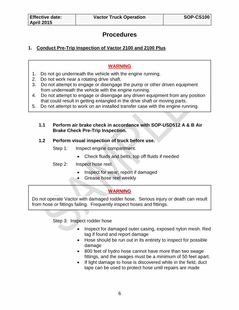
Step 1: Remove the inspection clamp and cover
Step 2: Inspect the filter screen for dust, dirt or debris daily.
Step 3: If the filter is dirty, raise debris body and put the safety prop in correct position.
Step 4: Remove all six wing nuts from top of filter housing, remove top.
Step 5: Remove nut from filter retaining cover, remove cover.
▪ Place rag over opening to prevent dirt from falling in
Effective date: April 2015
Vactor Truck Operation
SOP-CS100
9
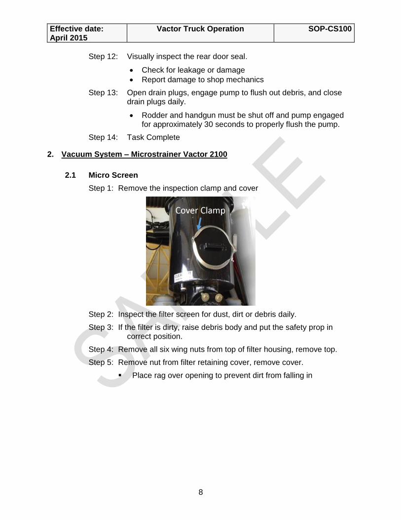
Step 6: Lift out stainless filter screen.
Step 7: Directing high-pressure water outward from the inside, thoroughly clean all material from grooves in filter screen.
Step 8: Reassemble filter screen, cover and housing, remove rag before replacing cover.
Step 9: Task Complete
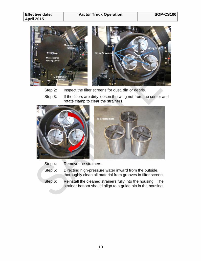
3. Vacuum System – Microstrainer Inspection of 2100 Plus
3.1 Micro Screens
Step 1: Open the cover daily.
NOTE
A drain is provided at the bottom of the microstrainer which is used to drain any excess moisture that has collected in the microstrainer during operations. It is closed during normal operations.
WARNING
Do not work in, under or around debris body without a correctly installed safety prop. Failure to do so may result in serious injury or death.
Effective date: April 2015
Vactor Truck Operation
SOP-CS100
10
Step 2: Inspect the filter screens for dust, dirt or debris.
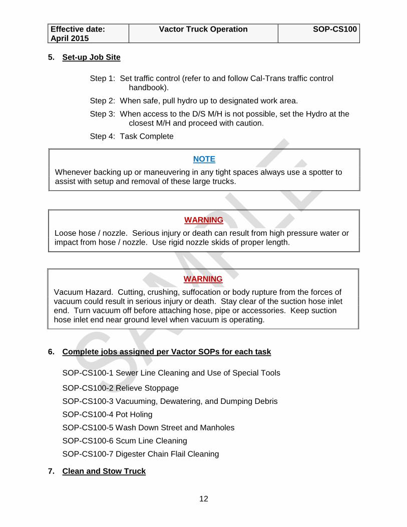
Step 3: If the filters are dirty loosen the wing nut from the center and rotate clamp to clear the strainers.
Step 4: Remove the strainers.
Step 5: Directing high-pressure water inward from the outside, thoroughly clean all material from grooves in filter screen.
Step 6: Reinstall the cleaned strainers fully into the housing. The strainer bottom should align to a guide pin in the housing.

Effective date: April 2015
Vactor Truck Operation
SOP-CS100
11
Step 7: Clean the housing cover seal.
Step 8: Rotate the clamp so each leg is centered on each of the strainers. Rotate each strainer so that the leg of the clamp is properly seated as shown in the cross bracing cutouts. Tighten the wingnut.
Step 9: Close the housing cover. While closing it may be necessary to wiggle it in to alignment with the locking screw. Tighten the wingnut.
Step 10: Check around the cover to verify that the cover is fully seated on the seal. Loosen and retighten as needed.
Step 11: Task Complete
4. Engaging and disengaging of Vactor 2100 and 2100 Plus
4.1 Follow instructions on visor of each truck to place in Work mode, Blower mode and/or Road mode.
NOTE
Two drain plugs are provided at the bottom of the microstrainer to drain any excess moisture that has collected in the microstrainer during operations. They are plugged during normal operations.
CAUTION
Do not attempt to disengage blower while it is still turning, damage to the transfer case may occur. When restarting the blower, make sure the blower has completely stopped turning before attempting to restart or before attempting to shift in or out of gear. Do not operate blower at less than 1200 RPM or more than its rated RPM. Never operate blower when vacuum exceeds its rated HG.
Effective date: April 2015
Vactor Truck Operation
SOP-CS100
12
5. Set-up Job Site
Step 1: Set traffic control (refer to and follow Cal-Trans traffic control handbook).
Step 2: When safe, pull hydro up to designated work area.
Step 3: When access to the D/S M/H is not possible, set the Hydro at the closest M/H and proceed with caution.
Step 4: Task Complete
6. Complete jobs assigned per Vactor SOPs for each task
SOP-CS100-1 Sewer Line Cleaning and Use of Special Tools
SOP-CS100-2 Relieve Stoppage
SOP-CS100-3 Vacuuming, Dewatering, and Dumping Debris
SOP-CS100-4 Pot Holing
SOP-CS100-5 Wash Down Street and Manholes
SOP-CS100-6 Scum Line Cleaning
SOP-CS100-7 Digester Chain Flail Cleaning
7. Clean and Stow Truck
NOTE
Whenever backing up or maneuvering in any tight spaces always use a spotter to assist with setup and removal of these large trucks.
WARNING
Loose hose / nozzle. Serious injury or death can result from high pressure water or impact from hose / nozzle. Use rigid nozzle skids of proper length.
WARNING
Vacuum Hazard. Cutting, crushing, suffocation or body rupture from the forces of vacuum could result in serious injury or death. Stay clear of the suction hose inlet end. Turn vacuum off before attaching hose, pipe or accessories. Keep suction hose inlet end near ground level when vacuum is operating.

Effective date: April 2015
Vactor Truck Operation
SOP-CS100
13
Step 1: Top off water tanks before returning to yard
Step 2: Dump any debris and rinse out debris hopper
Step 3: Fuel Truck
Step 4: Prop Debris Door Open
Step 5: Extend hose reel
Step 6: Clean cab of truck
Step 7: Task Complete

This Page Intentionally Left Blank
Sewer Line Cleaning & Use of Special Tools
Standard Operating Procedures
SOP-CS100-1 / July 2016
Author: Collections Services Owner: CS Manager Reviewers: CS Manager, CS Coach, CSW II

Effective date: July 2016
Sewer Line Cleaning & Use of Special Tools
SOP-CS100-1
2
This Page Intentionally Left Blank
Effective date: July 2016
Sewer Line Cleaning & Use of Special Tools
SOP-CS100-1
3
ADMINISTRATIVE
A. Introduction
1. This SOP contains the instructions and steps that District Employees will follow to clean sewer lines and use special tools. All work shall be performed safely in compliance with applicable standards and in a manner that minimizes adverse impacts.
B. Cancellation
2. SOP-CS100-1 Sewer Line Cleaning and Use of Special Tools, dated December 2012
3. SOP-CS100-1 Sewer Line Cleaning and Use of Special Tools, dated September 2014
References
4. Best Practices
5. Vactor Jet Rodder Operation Parts Service Manual, Vactor Manufacturing, Inc., October 2006
Objectives
6. Upon completion the operator will be aware of the steps to:
a. Use standard and spinning Nozzle in a drop hole
b. Forward clean
c. Clean a trunk line
d. Use a mill cutter
e. Use a turbo chain cutter
f. Use a chain flail
g. Use a chain flail with root saw attachment
Equipment/Personnel Required
7. Personnel
a. 2 CSW (At least one of which is a CSW II or Lead)
8. Equipment
a. Traffic Control devices
b. Portable gas detector

Effective date: July 2016
Sewer Line Cleaning & Use of Special Tools
SOP-CS100-1
4
c. Personal gas detector
d. Hose guides
e. Skids
f. Grease gun
g. Manhole hook
h. Suction pipe extensions
i. Clamps for suction pipe
j. Discharge hoses
k. Rollers
l. Nozzles
m. Hand tools
n. Clam shovel
o. Block book
p. Hydrant wrench
q. Gas tech
r. Drop hole guide and extractor tool
s. PPE
1) Hard hat
2) Gloves
3) Steel-toe safety shoes
4) Respiratory protection (when required)
5) Eye protection to include face shield if desired
6) Hearing protection
7) Class 2 safety vest
Terminology
9. NOTE is used when information is available that can assist the Operator in accomplishing his or her task.
10. CAUTION is used when special cautions must be taken by the Operator. Failure to following prescribed steps may cause serious bodily injury and damage equipment.
11. WARNING is used when special cautions must be taken by the Operator. Failure to follow prescribed steps will cause loss of life or limb and severely damage equipment.

Effective date: July 2016
Sewer Line Cleaning & Use of Special Tools
SOP-CS100-1
5
Employee Responsibility
1. Employees are responsible to follow District policies and procedures for the safe and effective operation of the District equipment.
Management Responsibility
1. Management is responsible to provide employees adequate education and training to safely and effectively operate District equipment.

Effective date: July 2016
Sewer Line Cleaning & Use of Special Tools
SOP-CS100-1
6
PROCEDURES
1. Sewer Line Cleaning
1.1 Drop Hole Access
Step 1: When working with a drop hole, use a hook with pipe extension to position nozzle in drop hole. Hold the skid with the hook while lowering the hose. When the nozzle is lined up with the drop hole, push it into the pipe. Pull up on the tiger tail rope and tie it off to hold the hose in place
In some applications the tiger tail rope can be wrapped once around the nozzle and used to align nozzle with drop hole
The drop hole guide can also be used to cradle the hose and align the nozzle with drop hole
Step 2: When the nozzle is lined up with the drop hole activate the rodder pump.
This should allow the hose to successfully travel past the vertical drop and up the sewer line while preventing the nozzle from propelling itself out of the manhole, or down the vertical drop where it might become stuck
NOTE
At any time when operating the hydro-jet in a location that involves traffic, set up traffic control.
CAUTION
Use portable gas detector prior to opening the manhole. Refer to and follow SOP-SAF519 Manhole Opening.
CAUTION
Do not raise throttle / pressure until the nozzle starts to move up the line. It may come out of the line. In case of drop hole, when using a hook with pipe extensions to insert the nozzle into a drop hole, check for overhead electric lines due to the risk of electrocution hazard.

Effective date: July 2016
Sewer Line Cleaning & Use of Special Tools
SOP-CS100-1
7
1.2 Standard & Spinning Nozzle
Step 1: Position hose guide roller over manhole and shift the truck from “ROAD” mode to “WORK” mode
Refer to in cab instruction for shifting the truck mode
Step 2: Note footage of line to be cleaned
Step 3: Select the most appropriate nozzle
Refer to the Work Order and nozzle matrix for selection of nozzle for specific application
Step 4: Attach the selected nozzle (with skids, if applicable) to the lead hose and lower into manhole with nozzle pointing upstream in channel
Step 5: Set footage counter to zero
Step 6: Increase throttle, and adjust water pressure.
When performing 72 month cleaning use 800 psi
Water pressure may need to be increased if 800 PSI is not enough to pull hose the full length of structure.
Step 7: Pay out hose.
Step 8: Observe footage counter and reduce reel speed as nozzle nears the end of line.
NOTE
In most cases the truck is positioned at the downstream manhole.
NOTE
Use lower pressure when cleaning 6” or shallow sewer line. Follow instructions / comments on Work Order.
CAUTION
Do not clean through multiple structures in high traffic/high speed areas, or where the manhole cannot be visually monitored by the cleaning crew. Manhole lid may flutter, raise up and cause damage to passing traffic.

Effective date: July 2016
Sewer Line Cleaning & Use of Special Tools
SOP-CS100-1
8
Step 9: When nozzle reaches desired footage, retract hose
When performing 72 month cleaning retrieval rate is 800 psi at 6 feet per second
When performing other cleaning, retrieval rate is between 1200-1500 psi at 2 feet per second unless noted differently on the work orders
Step 10: Pay attention to footage and stop retracting hose when lead hose reaches manhole
Step 11: Reduce throttle and shut off rodder pump
Allow water flow to stop, it may take several seconds
Step 12: Retract and secure hose for travel
Step 13: Switch truck from “WORK” mode to “ROAD”
Step 14: Task complete
1.3 Forward Cleaning Nozzle
Step 1: Position hose guide roller over manhole and shift the truck from “ROAD” mode to “WORK” mode
Refer to in cab instruction for shifting the truck mode
Step 2: Note footage of line to be cleaned
Step 3: Attach the forward cleaning nozzle with skids (if needed) to the lead hose and lower into manhole with nozzle pointing downstream in channel
The weight of the nozzle may cause the nozzle to tip forward when using a skid
Step 4: Set footage counter to zero
CAUTION
If the reel continues to rotate after the hose stops traveling, a “Rat’s Nest” of hose on the reel will be the result.
NOTE
Watch for debris and vacuum if necessary. For debris removal, refer to “SOP – CS100-3 Vacuuming, Dewatering, and Dumping Debris” for details.
Effective date: July 2016
Sewer Line Cleaning & Use of Special Tools
SOP-CS100-1
9
Step 5: Turn on rodder pump, increase throttle, and adjust to desired water pressure
Step 6: Pay out hose at approximately 2 ft/sec
Step 7: Observe footage counter and reduce throttle to idle when nozzle reaches the end of line
Step 8: Retract hose with rodder pump on and at minimum pressure
Step 9: Pay attention to footage and stop retracting hose when lead hose reaches manhole
Step 10: Adjust to desired pressure and clean structure again.
When using the forward cleaning nozzle. The line must be cleaned a minimum of two times.
Step 11: Observe footage counter and reduce throttle to idle when nozzle reaches the end of line
Step 12: Retract hose with rodder pump on and at minimum pressure.
Step 13: Pay attention to footage and stop retracting hose when lead hose reaches manhole
Step 14: When nozzle reaches manhole reduce throttle and shut off rodder pump
Allow water flow to stop, it may take several seconds
Step 15: Retract and secure hose for travel
Step 16: Switch truck from “WORK” mode to “ROAD”
Step 17: Task complete
1.4 Trunk Line Cleaning
Step 1: Position hose guide roller over manhole and shift the truck from “ROAD” mode to “WORK” mode
Refer to in cab instruction for shifting the truck mode
CAUTION
It is not advisable to use forward cleaning in 6” or shallow lines where potential flooding could occur.
NOTE
In most cases the truck is positioned at the downstream manhole.

Effective date: July 2016
Sewer Line Cleaning & Use of Special Tools
SOP-CS100-1
10
Step 2: Note footage of line to be cleaned
Step 3: Select the most appropriate nozzle
Refer to the nozzle matrix for selection of nozzle for specific application
Step 4: Attach the selected nozzle to the lead hose and lower into manhole with nozzle pointing upstream in channel
Step 5: Set footage counter to zero
Step 6: Turn on rodder pump, increase throttle, and adjust to desired water pressure
Step 7: Pay out hose
Step 8: Observe footage counter and reduce reel speed as nozzle nears the end of line
Step 9: When nozzle reaches desired footage slowly retract hose at approximately 1800 to 2000 psi at 1 ft/sec
Step 10: Pay attention to footage and stop retracting hose when lead hose reaches manhole
Step 11: Reduce throttle and shut off rodder pump
Step 12: Retract and secure hose for travel
Step 13: Switch truck from “WORK” mode to “ROAD”
Step 14: Task complete
NOTE
Watch for debris and vacuum if necessary. When large quantities of debris are encountered, additional cleaning of structure may be necessary. For debris removal, refer to “SOP_CS100-3 Vacuuming, Dewatering, and Dumping Debris”.
NOTE
Due to increased water consumption during this procedure, refilling the Vactor with fresh water after each structure may be necessary.
Effective date: July 2016
Sewer Line Cleaning & Use of Special Tools
SOP-CS100-1
11
2. Use of Special Tools
2.1 Mill Cutter
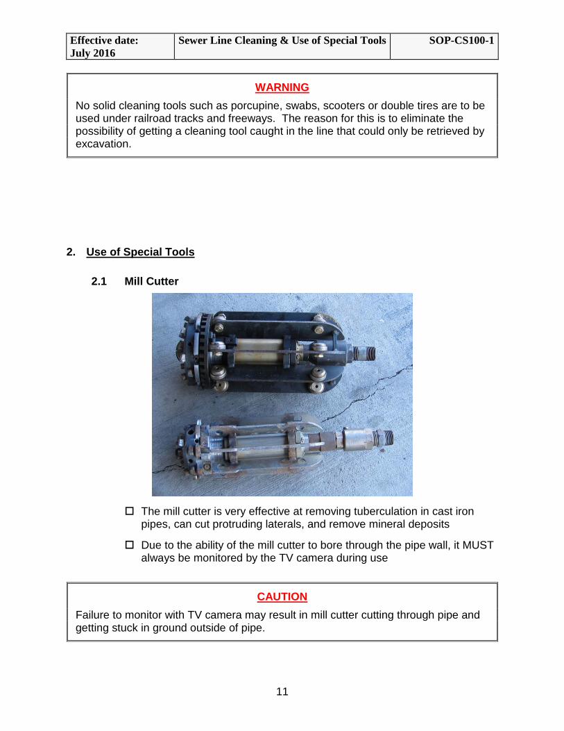
The mill cutter is very effective at removing tuberculation in cast iron pipes, can cut protruding laterals, and remove mineral deposits
Due to the ability of the mill cutter to bore through the pipe wall, it MUST always be monitored by the TV camera during use
WARNING
No solid cleaning tools such as porcupine, swabs, scooters or double tires are to be used under railroad tracks and freeways. The reason for this is to eliminate the possibility of getting a cleaning tool caught in the line that could only be retrieved by excavation.
CAUTION
Failure to monitor with TV camera may result in mill cutter cutting through pipe and getting stuck in ground outside of pipe.

Effective date: July 2016
Sewer Line Cleaning & Use of Special Tools
SOP-CS100-1
12
Before and after using mill cutter, make sure all carbide teeth are secured and in good condition
Use the extractor tool when removing mill cutter.
2.2 Chain Cutter
The chain cutter is effective at removing mineral deposits, and hardened grease
Large quantity of mineral deposits removed by chain cutter can accumulate behind it preventing retrieval. Remove accumulated debris as you progress to prevent getting stuck in the line.
Visually inspect chain before and after use. Ensure the chain is secured and of proper length for the line
When extracting the large chain cutters use the extractor tool to aid in the removal and eliminate damage to skids
2.3 Chain Flail
NOTE
Due to the size and weight of the mill cutter, extracting it out of the sewer line can be strenuous and difficult. To reduce hazards and risks associated with the task, use extractor tool when necessary.
NOTE
Due to the chain cutter’s ability to fit snuggly, use extractor tool to reduce hazards and risks involved with removal of chain cutters.

Effective date: July 2016
Sewer Line Cleaning & Use of Special Tools
SOP-CS100-1
13
The chain flail removes grease, light scale, and minor roots
Visually inspect chain before and each after use. Insure the chain is secured and of proper length for the line.
2.4 Chain Flail with Root Saw Attachment
The root saw removes roots and grease
Make sure to use the correct size saw blade for the line
Make sure blade rotates freely before placing saw in the line.
If severe roots are encountered, it may be necessary to work the saw back and forth to cut the root mass, or saw the line with a smaller diameter blade first.
It can get hung up on offset joints

Effective date: July 2016
Sewer Line Cleaning & Use of Special Tools
SOP-CS100-1
14