westermo_user_guide_ma-21.pdf
DESCRIPTION
User guide 20mA curent loop converterTRANSCRIPT

StrömslingeomvandlareCurrent Loop ConverterStromschleifenwandler
INSTALLATIONSANVISNINGINSTALLATION MANUAL
INSTALLATIONS ANLEITUNG6021-2002
www.westermo.se
MA-21 AC
MA-21 DC
©W
este
rmo
Tele
indu
stri
AB
• 19
98 •
REV
. A
GalvanicIsolation
TransientProtection
BalancedTransmission
CEApproved
8 6021-2002
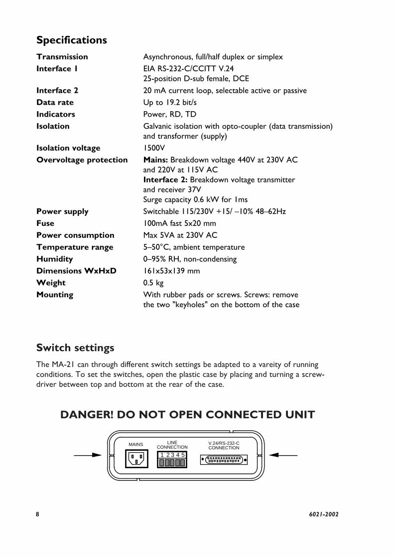
Switch settingsThe MA-21 can through different switch settings be adapted to a vareity of running conditions. To set the switches, open the plastic case by placing and turning a screw-driver between top and bottom at the rear of the case.
DANGER! DO NOT OPEN CONNECTED UNIT
1 2 3 4 5
V.24/RS-232-CCONNECTION
LINECONNECTION
MAINS
SpecificationsTransmission Asynchronous, full/half duplex or simplexInterface 1 EIA RS-232-C/CCITT V.24
25-position D-sub female, DCEInterface 2 20 mA current loop, selectable active or passiveData rate Up to 19.2 bit/sIndicators Power, RD, TDIsolation Galvanic isolation with opto-coupler (data transmission)
and transformer (supply)Isolation voltage 1500V Overvoltage protection Mains: Breakdown voltage 440V at 230V AC
and 220V at 115V ACInterface 2: Breakdown voltage transmitter and receiver 37VSurge capacity 0.6 kW for 1ms
Power supply Switchable 115/230V +15/ –10% 48–62HzFuse 100mA fast 5x20 mmPower consumption Max 5VA at 230V ACTemperature range 5–50°C, ambient temperatureHumidity 0–95% RH, non-condensingDimensions WxHxD 161x53x139 mmWeight 0.5 kgMounting With rubber pads or screws. Screws: remove
the two "keyholes" on the bottom of the case
96021-2002
AAAAAAAAA
ONOFF
S4
1 - 6ONOFF
S5 S1
1 - 91 - 6 1 - 4
S2S3
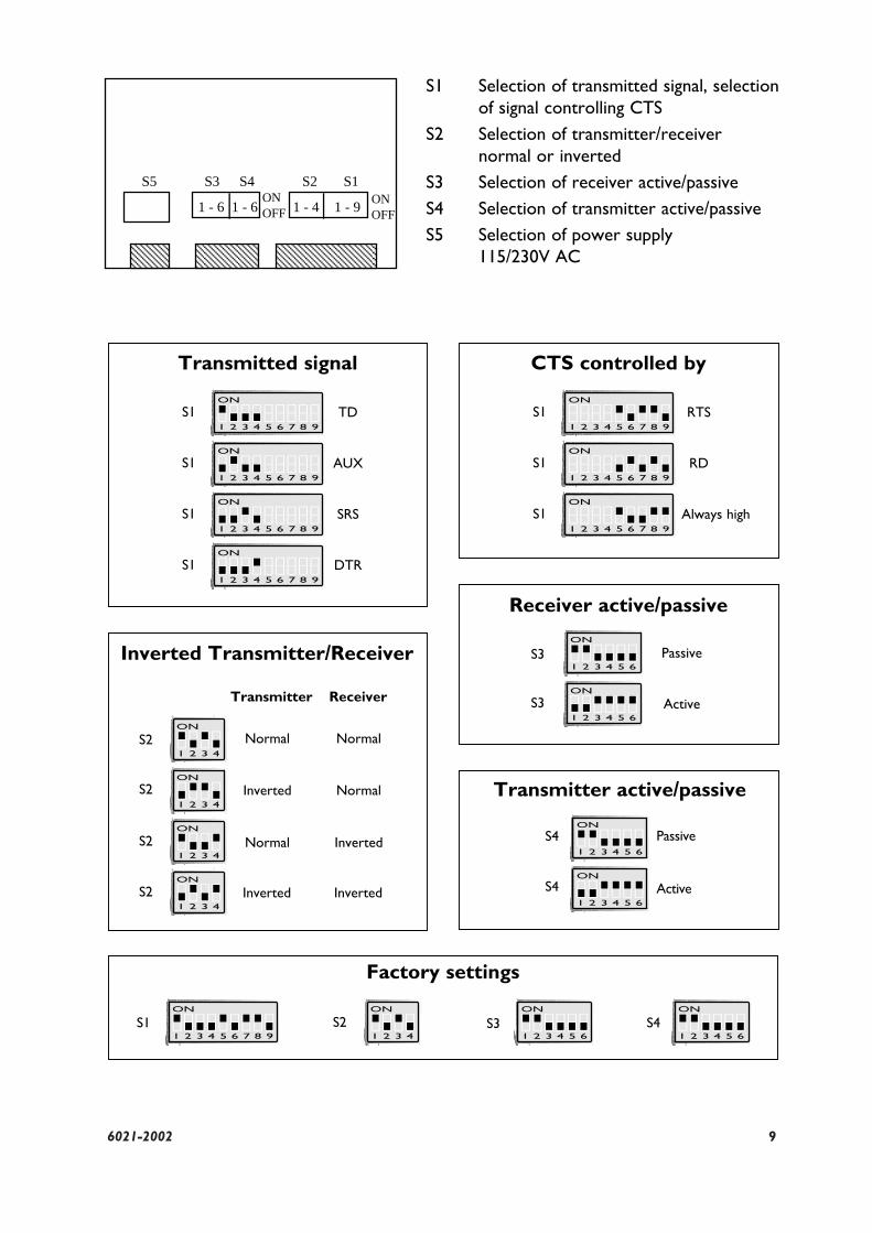
S1 Selection of transmitted signal, selectionof signal controlling CTS
S2 Selection of transmitter/receivernormal or inverted
S3 Selection of receiver active/passiveS4 Selection of transmitter active/passiveS5 Selection of power supply
115/230V AC
Receiver active/passive
Factory settings
S3
S3
ON
1 2 3 4 5 6
ON
1 2 3 4 5 6
Transmitter active/passive
PassiveS4
ActiveS4
ON
1 2 3 4 5 6
ON
1 2 3 4 5 6
Passive
Transmitted signal
Active
ON
1 2 3 4 5 6 7 8 9
TDS1
ON
1 2 3 4 5 6 7 8 9S1
ON
1 2 3 4 5 6 7 8 9
AUXS1
ON
1 2 3 4 5 6 7 8 9
SRSS1
ON
1 2 3 4 5 6 7 8 9
DTRS1
CTS controlled by
ON
1 2 3 4 5 6 7 8 9
RTSS1
ON
1 2 3 4 5 6 7 8 9
RDS1
ON
1 2 3 4 5 6 7 8 9
Always highS1
Inverted Transmitter/Receiver
Transmitter
Normal Normal
Normal
Inverted
Inverted
Inverted
Normal
Inverted
Receiver
S2
S2
S2
S2
ON
1 2 3 4
ON
1 2 3 4
ON
1 2 3 4
ON
1 2 3 4
S2ON
1 2 3 4S3
ON
1 2 3 4 5 6S4
ON
1 2 3 4 5 6
10 6021-2002
Cable
42pF/m0.3mm2
1200
5000m
600
6000m
2400
4000m
4800
3000m
9600
500m
19200
200m
I 2 103 TD/Transmitted DataO 3 104 RD/Received DataI 4 105 RTS/Request To Send
O 5 106 CTS/Clear To SendO 6 107 DSR/Data Set Ready– 7 102 SG/Signal GroundO 8 109 DCD/Data Carrier DetectI 11 – AUX/AuxiliaryI 19 120 SRS/Secondary Request to SendI 20 108/2 DTR/Data Terminal Ready
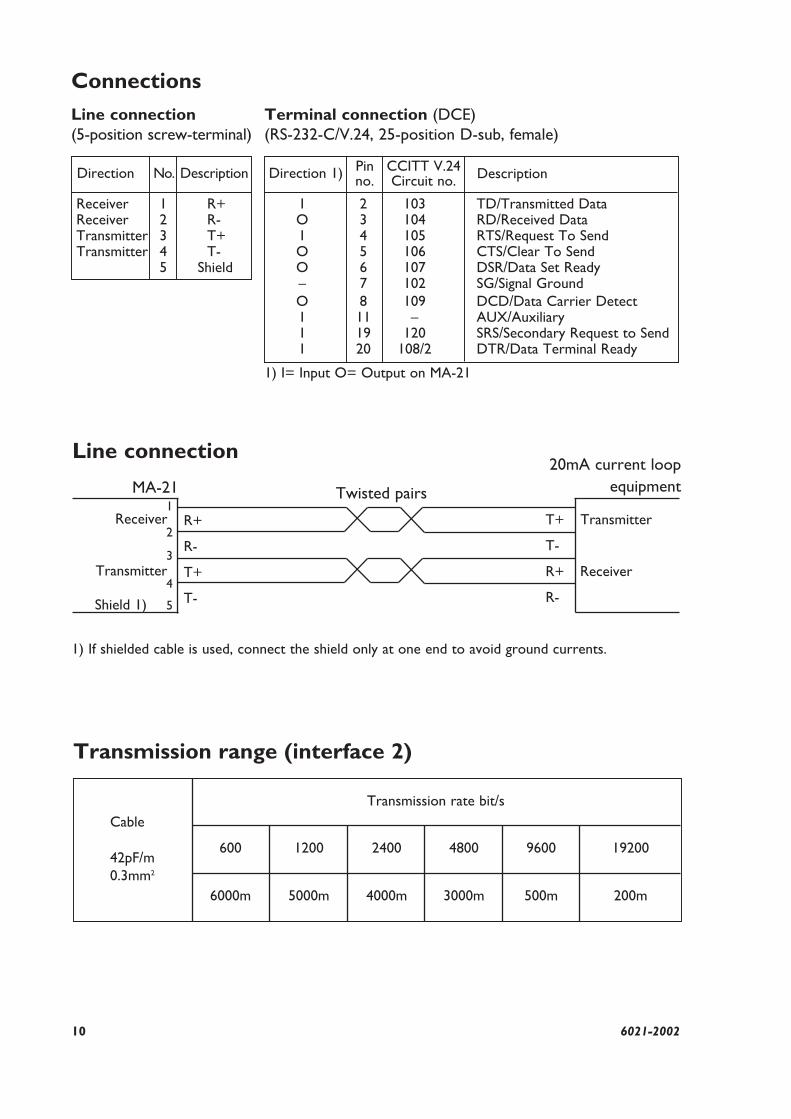
Receiver 1 R+Receiver 2 R-Transmitter 3 T+Transmitter 4 T-
5 Shield
No.
1) I= Input O= Output on MA-21
Direction Description DescriptionDirection 1) Pinno.
CCITT V.24Circuit no.
ConnectionsLine connection(5-position screw-terminal)
Terminal connection (DCE)(RS-232-C/V.24, 25-position D-sub, female)
5
Line connection
Transmitter
Receiver
Receiver
Transmitter
Shield 1)
4
3
2
1R+
R-
T+
T-
T+
T-
R+
R-
MA-21 Twisted pairs
20mA current loopequipment
1) If shielded cable is used, connect the shield only at one end to avoid ground currents.
Transmission range (interface 2)
Transmission rate bit/s
116021-2002
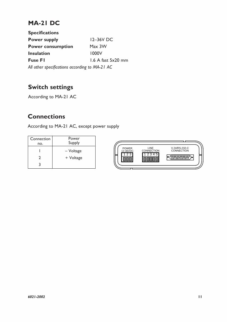
1 – Voltage
2 + Voltage
3
MA-21 DCSpecifications Power supply 12–36V DCPower consumption Max 3WInsulation 1000VFuse F1 1.6 A fast 5x20 mmAll other specifications according to MA-21 AC
Switch settingsAccording to MA-21 AC
ConnectionsAccording to MA-21 AC, except power supply
Connectionno.
PowerSupply
1 2 3 4 5
V.24/RS-232-CCONNECTION
LINECONNECTION
1 2 3
POWER12-36VDC
12 6021-2002
HintsThe 20mA current loop interface, or TTY as it is sometimes known, is a popularindustrial communications standard. The system relies on a current generator running on both the transmit and receive circuits. On each circuit it is important to have onlyone current generator supplying current into that circuit. For this reason the MA-21 can have it’s current generators set to be either active or passive. It is important tocheck the state of all attached equipment to ensure correct setting on the MA-21. The MA-21 has the same line interface as MD-21, MD-29 and are hence compatible.
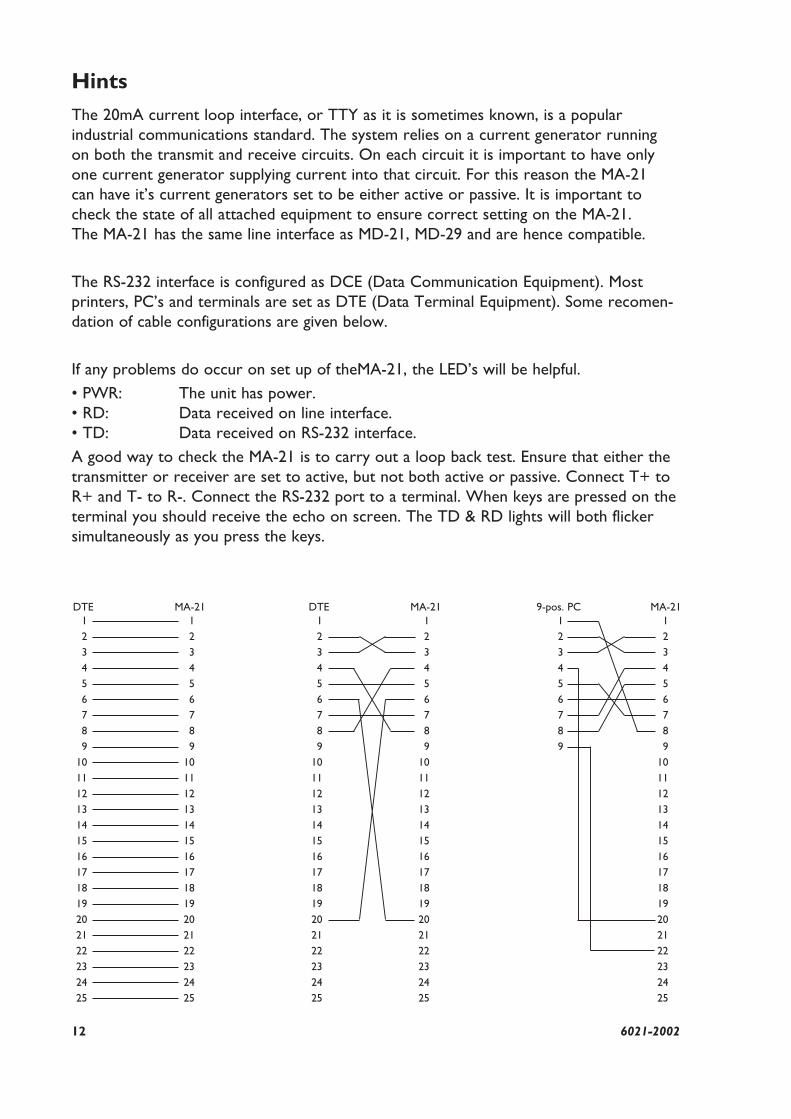
The RS-232 interface is configured as DCE (Data Communication Equipment). Mostprinters, PC’s and terminals are set as DTE (Data Terminal Equipment). Some recomen-dation of cable configurations are given below.
If any problems do occur on set up of theMA-21, the LED’s will be helpful.• PWR: The unit has power.• RD: Data received on line interface.• TD: Data received on RS-232 interface.A good way to check the MA-21 is to carry out a loop back test. Ensure that either thetransmitter or receiver are set to active, but not both active or passive. Connect T+ toR+ and T- to R-. Connect the RS-232 port to a terminal. When keys are pressed on theterminal you should receive the echo on screen. The TD & RD lights will both flickersimultaneously as you press the keys.
123456789
10111213141516171819202122232425
123456789
10111213141516171819202122232425
123456789
123456789
10111213141516171819202122232425
123456789
10111213141516171819202122232425
123456789
10111213141516171819202122232425
DTE MA-21 DTE MA-21 9-pos. PC MA-21
136021-2002
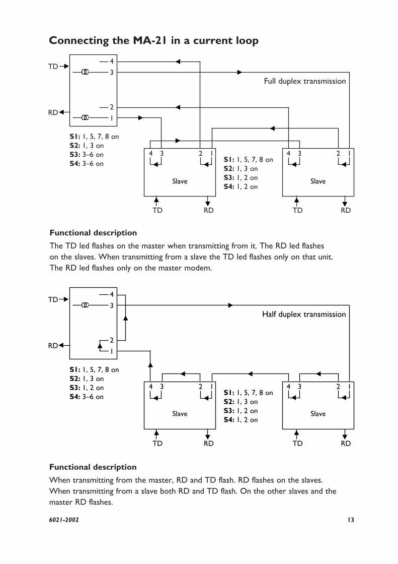
Connecting the MA-21 in a current loop
4
3
4 3
RD
2 1
2
1
4 3 2 1
TD TD
TD
S1: 1, 5, 7, 8 onS2: 1, 3 onS3: 3–6 onS4: 3–6 on S1: 1, 5, 7, 8 on
S2: 1, 3 onS3: 1, 2 onS4: 1, 2 on
RD
RD
Functional description
The TD led flashes on the master when transmitting from it. The RD led flashes on the slaves. When transmitting from a slave the TD led flashes only on that unit. The RD led flashes only on the master modem.
Functional description
When transmitting from the master, RD and TD flash. RD flashes on the slaves. When transmitting from a slave both RD and TD flash. On the other slaves and themaster RD flashes.
Full duplex transmission
4
3
4 3
RD
2 1
2
1
4 3 2 1
TD
Slave Slave
SlaveSlave
TD
TD
S1: 1, 5, 7, 8 onS2: 1, 3 onS3: 1, 2 onS4: 3–6 on S1: 1, 5, 7, 8 on
S2: 1, 3 onS3: 1, 2 onS4: 1, 2 on
RD
RD
Half duplex transmission
Westermo Teleindustri AB • S-640 40 Stora Sundby, SwedenPhone +46 16 612 00 Fax +46 16 611 80
E-mail: [email protected] • Westermo Web site: www.westermo.se
Westermo Teleindustri AB have distributors in several countries,contact us for further information.
Westermo Data Communications GmbHBruchsaler Straße 18, 68753 WaghäuselTel.: +49(0)7254-95400-0 • Fax.:+49(0)7254-95400-9E-Mail: [email protected]
Westermo Data Communications LtdSolent Business Centre • Millbrook Road WestMillbrook, Southampton • SO15 0HWPhone: +44(0)1703-704 611 • Fax.:+44(0)1703 702 682E-Mail: [email protected]
Subsidiaries
V.24/RS-232
PE
SG
Line
T+
T-
TDAUXSRSDTR
DSR
DCD
PG
PowerSupply
R+
R-
CTSRTS
RD
Shield7
0V
+12V6
8
3420
19
1211
2
TD
2)S1
3
S2
R51 R47
+24VB
0V
0VB
+12V
-12V
Isolated power supply
F1
1
+12V
1
2
0VB
14256
3
4
20mA
+24VB
R49
PE
1
0VB
1425
6
3
2
20mA
+24VB
R50
PE
R48
PE
S4
RD
34
S2874
5
9
S1
653
1) 1) 1)
1)
+12V
PWR
50VB
S3
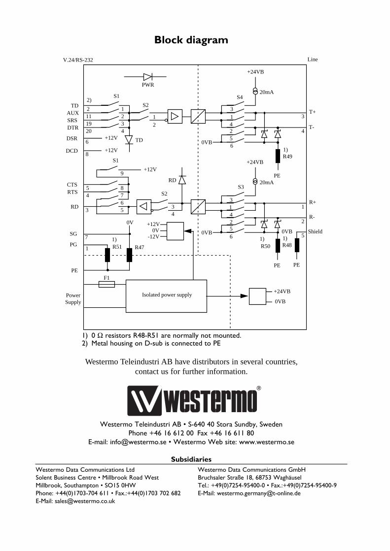
Block diagram
1) 0 Ω resistors R48-R51 are normally not mounted. 2) Metal housing on D-sub is connected to PE