what are heat exchangers for? heat exchangers are practical devices used to transfer energy from...
TRANSCRIPT


What are heat exchangers for?
Heat exchangers are practical devices used to transfer energy from one fluid to another
To get fluid streams to the right temperature for the next process
– reactions often require feeds at high temp.
To condense vapours
To evaporate liquids
To recover heat to use elsewhere
To reject low-grade heat
To drive a power cycle
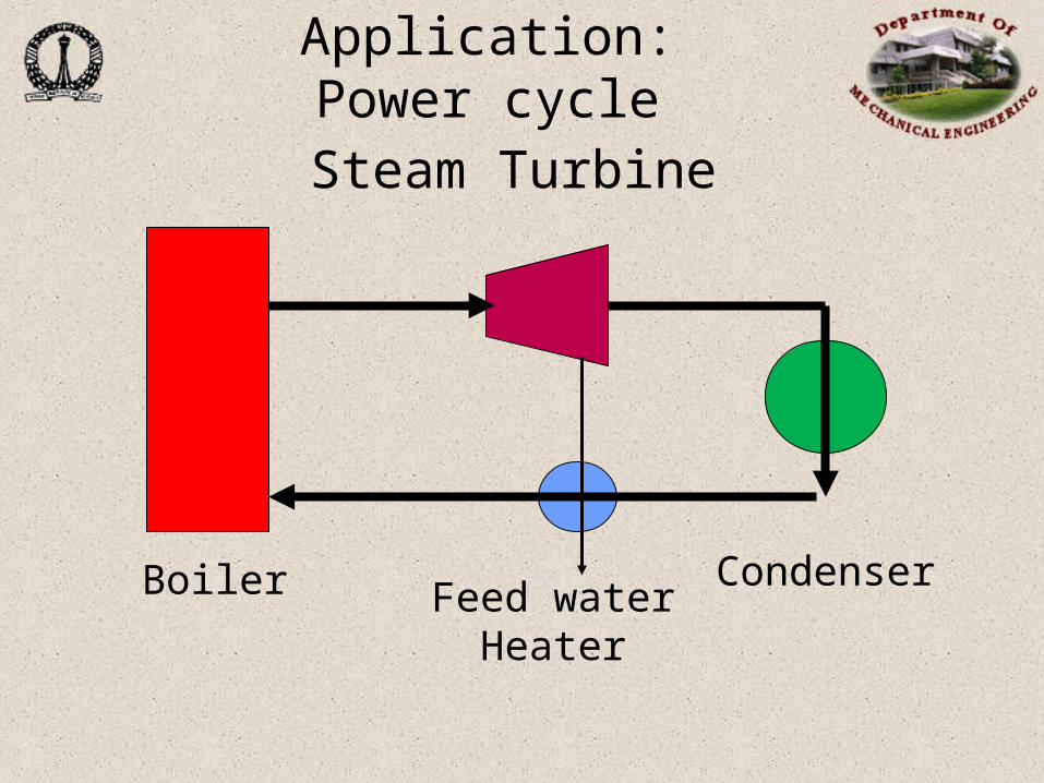
Application: Power cycle
Steam Turbine
Boiler CondenserFeed water
Heater
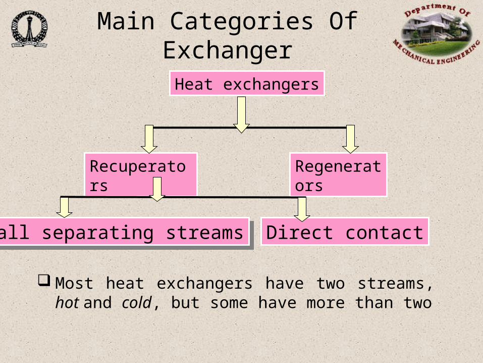
Main Categories Of Exchanger
Most heat exchangers have two streams, hot and cold, but some have more than two
Heat exchangers
Recuperators Regenerators
Wall separating streamsWall separating streams Direct contact

Recuperators/Regenerators
Recuperative:Recuperative:
Has separate flow paths for each fluid
which flow simultaneously through the
exchanger transferring heat between
the streams
RegenerativeRegenerative
Has a single flow path which the hot
and cold fluids alternately pass
through.
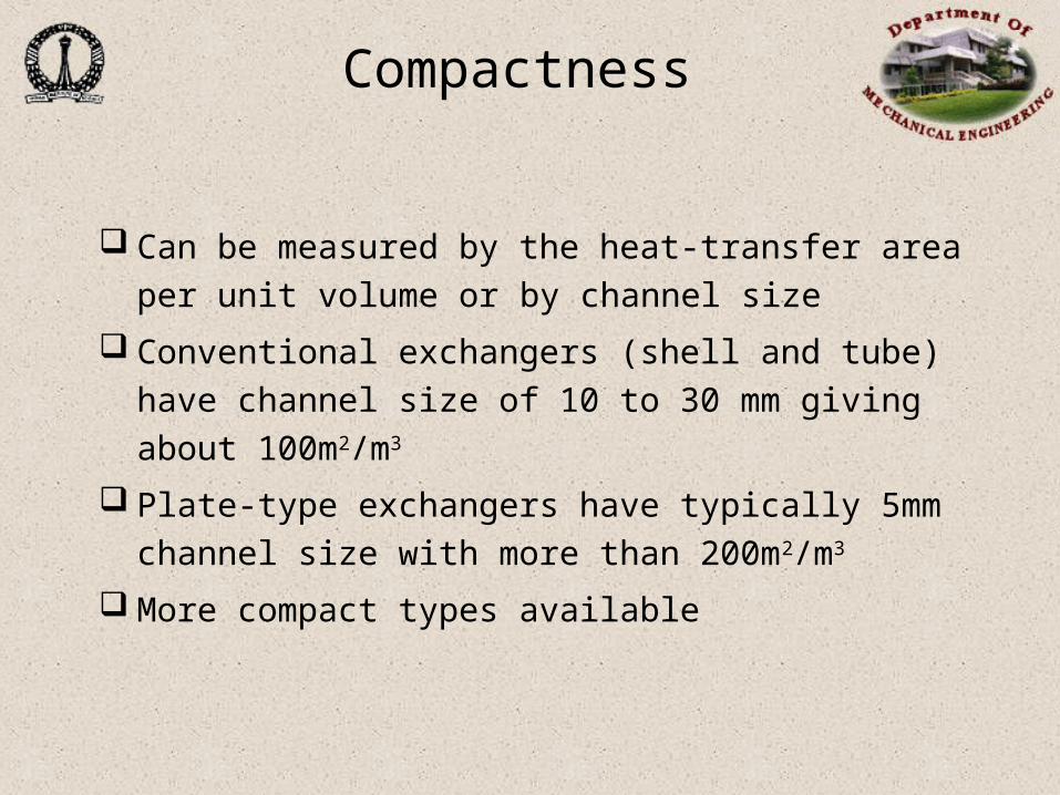
Compactness
Can be measured by the heat-transfer area per unit volume
or by channel size
Conventional exchangers (shell and tube) have channel
size of 10 to 30 mm giving about 100m2/m3
Plate-type exchangers have typically 5mm channel size
with more than 200m2/m3
More compact types available
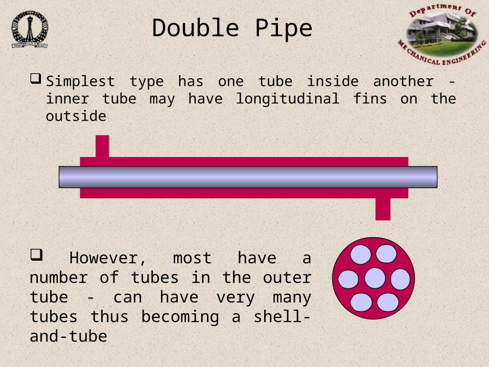
Double Pipe
Simplest type has one tube inside another - inner tube may have longitudinal fins on the outside
However, most have a number of tubes in the outer tube - can have very many tubes thus becoming a shell-and-tube

Shell and Tube
Typical shell and tube exchanger as used in the process industry

Shell-Side Flow
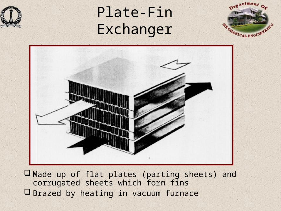
Plate-Fin Exchanger
Made up of flat plates (parting sheets) and corrugated sheets which form fins
Brazed by heating in vacuum furnace
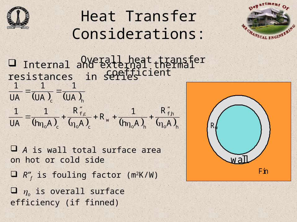
Heat Transfer Considerations:
Overall heat transfer coefficient
Internal and external thermal resistances in series
ho
h,f
how
co
c,f
co
hc
A
R
Ah
1R
A
R
Ah
1
UA
1
UA
1
UA
1
UA
1
A is wall total surface area on hot or cold side
R”f is fouling factor (m2K/W)
o is overall surface efficiency (if finned)
Rw
wallFin
Fouling factor
Material deposits on the surfaces of the heat exchanger tube may add further resistance to heat transfer in addition to those listed above. Such deposits are termed fouling and may significantly affect heat exchanger performance. Scaling is the most common form of fouling and is associated with inverse solubility salts. Examples of such salts are CaCO3, CaSO4, Ca3(PO4)2, CaSiO3, Ca(OH)2, Mg(OH)2, MgSiO3, Na2SO4, LiSO4, and Li2CO3.
Corrosion fouling is classified as a chemical reaction which involves the heat exchanger tubes. Many metals, copper and aluminum being specific examples, form adherent oxide coatings which serve to passivity the surface and prevent further corrosion.
Heat Transfer Considerations (contd…):

Chemical reaction fouling involves chemical reactions in the process stream which results in deposition of material on the heat exchanger tubes. When food products are involved this may be termed scorching but a wide range of organic materials are subject to similar problems.
Freezing fouling is said to occur when a portion of the hot stream is cooled to near the freezing point for one of its components. This is most notable in refineries where paraffin frequently solidifies from petroleum products at various stages in the refining process, obstructing both flow and heat transfer.
Biological fouling is common where untreated water is used as a coolant stream. Problems range from algae or other microbes to barnacles.
Heat Transfer Considerations (contd…):

Fluid R”, m2K/Watt
Seawater and treated boiler feedwater (below 50oC) 0.0001 Seawater and treated boiler feedwater (above 50oC) 0.0002 River water (below 50oC) 0.0002-0.001 Fuel Oil 0.0009 Regrigerating liquids 0.0002 Steam (non-oil bearing) 0.0001
Heat Transfer Considerations (contd…):

T2
t1
T1
t2
Parallel FlowT1
T2
t1 t2
Position
Tem
pera
ture
T2
t2
T1
t1
Counter FlowT1
T2
t2 t1Te
mpera
ture
Position
Basic flow arrangement in tube in tube flow

Heat Exchanger AnalysisLog mean temperature difference (LMTD)
method
fluid cold andhot between Tmean some ismT Where
mTUA.Qrelation a Want
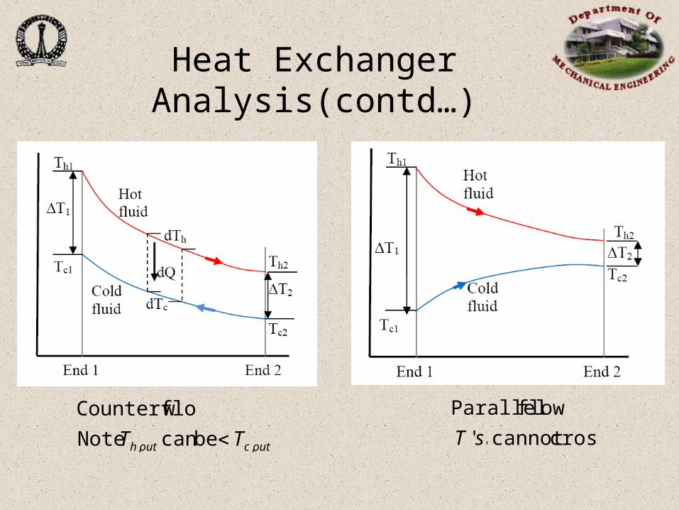
Heat Exchanger Analysis(contd…)
outcouth TT ,, be can Note
wCounterflo
crosscannot '
flow Parallel
'sT
Heat Exchanger Analysis (contd…)
hhccch
ccc
hhh
ch
ccchhh
cmcmQdTTd
cm
QddT
cm
QddT
TTUdAQd
c
m
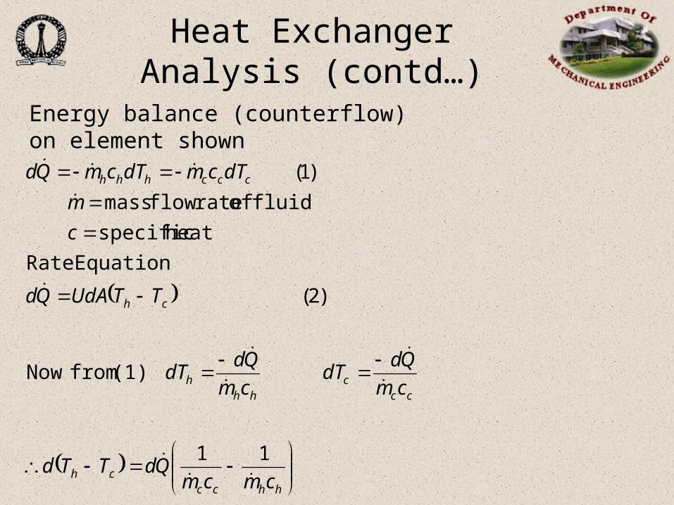
dTcmdTcmQd
11
(1) fromNow
)2(
EquationRate
heat specific
fluid of rateflow mass
)1(
Energy balance (counterflow) on element shown
Heat Exchanger Analysis (contd…)
2121
11
22
and
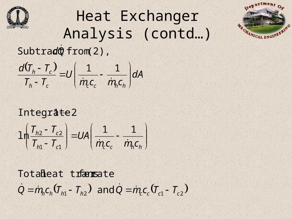
ratefer heat trans Total
11ln
21 Integrate
11
(2), from Subtract
cccchhhh
hhccch
ch
hhccch
ch
TTcmQTTcmQ
cmcmUA
TT
TT
dAcmcm
UTT
TTd
Qd

Heat Exchanger Analysis (contd…)
• Remember – 1 and 2 are ends, not fluids
• Same formula for parallel flow (but T’s are different)
•Counterflow has highest LMTD, for given T’s therefore smallest area for Q.
Difference eTemperaturMean Log is LMTD
LMTD
/ln
2
1
put and mfor Substitute
12
12
222
111
c
UAQ
TT
TTUAQ
ENDTTT
ENDTTT
ch
ch
Heat Exchanger Analysis (contd…)
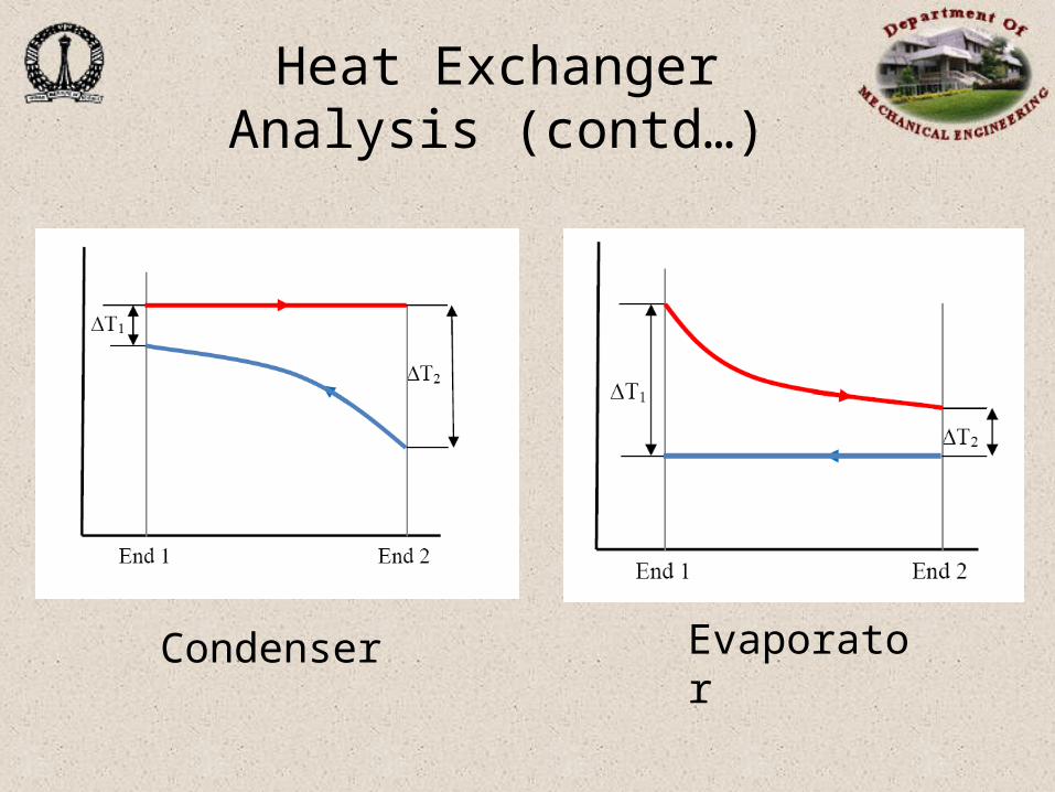
Condenser Evaporator
Multipass HX Flow Arrangements
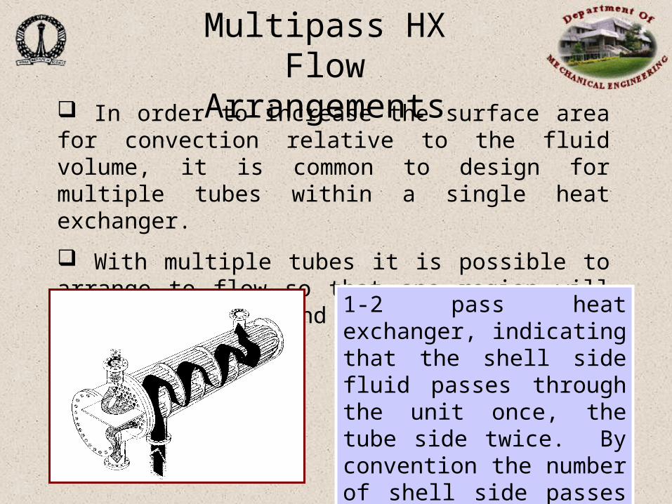
In order to increase the surface area for convection relative to the fluid volume, it is common to design for multiple tubes within a single heat exchanger.
With multiple tubes it is possible to arrange to flow so that one region will be in parallel and another portion in counter flow.
1-2 pass heat exchanger, indicating that the shell side fluid passes through the unit once, the tube side twice. By convention the number of shell side passes is always listed first.

The LMTD formulas developed earlier are no longer adequate for multipass heat exchangers. Normal practice is to calculate the LMTD for counter flow, LMTDcf, and to apply a correction factor, FT, such that
CFTeff LMTDF
The correction factors, FT, can be found theoretically and presented in analytical form. The equation given below has been shown to be accurate for any arrangement having 2, 4, 6, .....,2n tube passes per shell pass to within 2%.
Multipass HX Flow Arrangements (contd…)

1R1RP2
1R1RP2ln1R
PR1P1
ln1RF
2
2
2
T
12
21 ratioCapacity tt
TTR
1Rfor ,1
:essEffectiven /1
/1
shell
shell
N
N
XR
XP
1Rfor , 1NPN
PP
shelloshell
o
11
12o tT
ttP
1
1
o
o
P
RPX
T,t = Shell / tube side; 1, 2 = inlet / outlet
Multipass HX Flow Arrangements (contd…)
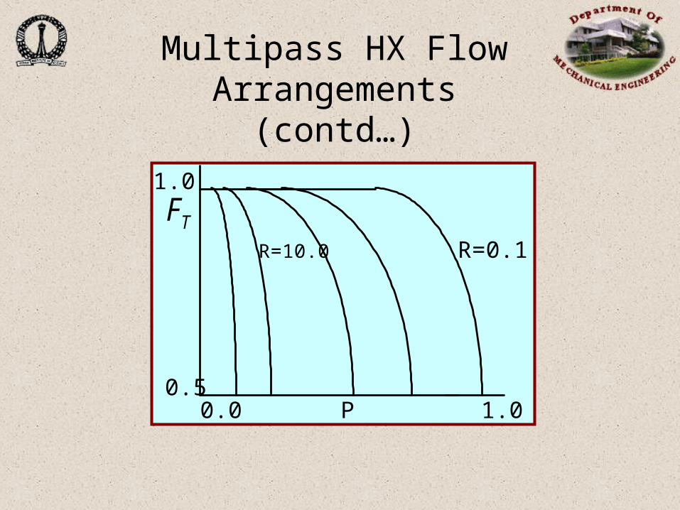
R=0.1
1.0
0.50.0 1.0P
R=10.0
FT
Multipass HX Flow Arrangements (contd…)

havecan ratecapacity heat
C ,C oflesser with fluid only thethen
since and
fluid One
H.Ex. long infinitelyan for is where
:esseffectiven Define
? conditionsinlet
given for perform Ex. H. existing willHow
max
BA
A
,,max
max
max
T
TCTC
TcmTcmQ
TTTT
Q
Q
Q
BBA
BBAA
incinh
actual
Effectiveness-NTU Method

max
min
minmax
min
max
min
min
in.cin.hmin
in.cin.hminmaxminmax
CC
1CUA-
expCC
1
CC
1CUA-
exp-1
......... )LMTD(UAQ intoback Substitute
sT'outlet contain not does which for expressionWant
TTCQ or,
TTC
Q and TCQ i.e.
min
max
min
HEx.) of (size units transfer of No. and
,
C
UANTU
C
CNTU
Effectiveness-NTU Method(contd…)

Charts for each Configuration
Procedure:
Determine Cmax, Cmin/Cmax
Get UA/Cmin, from chart
incinh TTCQ ..min

Effectiveness-NTU Method(contd…)
U
CNTUA
C
UANTU minmax
minmax
• NTUmax can be obtained from figures in textbooks/handbooks
First, however, we must determine which fluid has Cmin