what is a riser pole arrester - arresterworks, consultants, arrester… 006... · flashover that...
TRANSCRIPT

ArresterFacts 025 What is a Deadfront and Separable Arrester
Copyright ArresterWorks 2008-2011 Jonathan J. Woodworth Page1
Arrester Forensics How to determine the cause of an
arrester’s last overload
ArresterFacts 006
ArresterWorks
5/18/2013 Jonathan Woodworth

ArresterFacts 006 Arrester Forensics - How to determine the cause of an arrester’s last overload
ArresterFacts Copyright 2008-2011 Jonathan J. Woodworth Page 2
Figure 1 Porcelain Station Arresters with internal core that has experienced a fault current event
Arrester Forensics How to determine the cause of an arrester’s last overload
Contents Introduction
Definitions
Purpose of a Forensic Analysis
Companion Arresters
Relevant Data to Collect
15 Step Analysis Procedure
Common Root Causes of Overload or Failure
Seal Pumping Explained
Introduction The purpose of this ArresterFacts is to offer
better understanding on the subject of
arrester forensics to the engineer,
technician or any stakeholder reporting on
why an arrester has failed or been
overloaded. Forensics in this case means
the evaluation of an arrester or
arrester components to
determine the reason why it or its
companion arrester has become
inoperative. Arresters are surge
diverters for lightning and
switching surges that can at
times be overloaded; resulting in
their end of useful life. This
ArresterFacts gives clear
reasoning behind the tests and
techniques used in the search for
the root cause of an arrester’s
terminal overload.
Definitions A terminal overload is an event
where the arrester is stressed
beyond its capability to the point
of rendering it un-useable. The
arrester may or may not be in
one piece after the event. The arrester may
electrically be an open circuit or a short
circuit. The terminal overload may be a
failure but this is not always the case. If an
arrester is terminally overloaded after a very
long service life and during an overvoltage
event where it successfully protected a
much higher valued asset to which it was
meant to protect, then this terminal overload
can hardly be called an arrester failure. In
fact, the scenario just mentioned should be
termed an arrester success and not an
arrester failure as it is often called.
However if an arrester becomes inoperative
within days of its first energization, with no
surge events occurring, then it is quite
possible that it is an arrester failure.

ArresterFacts 006 - Arrester Forensics How to determine the cause of an arrester’s terminal overload
Copyright ArresterWorks 2013 Page 3
Purpose of a Forensic Analysis It is the responsibility of the arrester forensic
analyst to determine if the terminal overload
was an arrester failure or an arrester
success. Often times the underlying
reason for an analysis is that several
arresters of similar style have experienced a
terminal overload and the organization
requesting the analysis needs to know if the
problem is isolated or system wide. If it is a
system wide issue and is indeed a failure
issue, then perhaps a different mitigation
strategy would be used than if it was an
isolated event. Sometimes the purpose of
an analysis is to determine if there is a
power system issue that is not related to the
arresters, but since the arresters are
overvoltage protectors, they result in a
terminal overload. The cost of a
misdiagnosis can be very expensive. If the
cause of the overload is incorrectly
identified as a system issue, literally millions
of dollars can be spent trying to correct the
wrong thing.
Companion Arresters The importance of companion arresters in a
forensic analysis cannot be stressed
enough. A companion arrester is one of
similar vintage and type that may be on the
same phase near the overloaded arrester or
on a separate phase in a nearby location. It
is preferred that the companion arrester not
be overloaded or blown. Unfortunately an
arrester that has experienced the terminal
overload has much of the forensic evidence
damaged or completely covered by the
power frequency fault current damage.
The power frequency fault current most
often flows off the system along the arrester
to earth during the terminal event and raises
the temperature of the arrester components
past their melting point leaving them nearly
unrecognizable.
Trick of the Trade: If at all possible,
obtain a companion arrester and it will be
well worth the extra effort when looking for
the overload root cause.
Relevant System Data Collecting relevant system data is often the
most difficult part of a forensic analysis of
arresters. The data that can be beneficial to
the analysis are as follows:
1. System voltage
2. Neutral configuration of the source
transformer. Grounded, floating,
impedance grounded.
3. Magnitude of available fault current.
4. Location of the arrester relative to
other equipment
5. Other equipment that may be on the
same phase in the same substation
or on the same line. Capacitors,
switches, breakers, transformers,
inductors.
6. Status of other equipment during
and after the event. Question if they
had experienced an overload or
failure recently.
7. History of the overload location.
Question if there had been other
overloads in the past few years.
8. Switching or lightning activity on the
day of the event or in prior weeks.
9. Performance history of the arrester
vintage and type on the same
system.
10. The existence of any other forensic
analysis data that may offer clues to
the root cause.
Trick of the Trade: Beware of irrelevant
data. Often times the dates and locations,
of events surrounding the overload are
incorrect or inaccurate. Double check the
data with multiple sources.

ArresterFacts 006 - Arrester Forensics How to determine the cause of an arrester’s terminal overload
Copyright ArresterWorks 2013 Page 4
Figure 3 A Group Analyses can be highly beneficial. Even the most novice observer can often shed light on the issue
A 15 Step Analysis
Procedure Of course each analysis will be different
from the previous ones, but there are some
routines that will make the analysis much
more effective.
1. Gather as much system data as
possible, from as many sources as
possible.
2. Trick of the Trade: If at all possible,
perform the analysis with a group. The
group can be novice to expert in
experience; everyone will have
something useful to offer.
3. Inspect the subject arresters initially and
record as much data as possible from
the tags, shipping tags, and name
plates.
4. If possible, collect original catalog
literature on the subject arrester from
old catalogs or from online sites.
5. Start a comprehensive set of
photographs of the received parts.
6. If a complete arrester (overloaded or
companion) is available, perform
electrical tests on the complete sample
including Vref, watts loss, PD, and
leakage.
7. Trick of the Trade: If any of the
arresters are sealed with an internal air
volume, a gas analysis may be quite
revealing. If this is desired, then before
the arrester is disassembled, a gas
sample should be drawn and analyzed.
See Figure 2
8. Carefully and meticulously disassemble
the arrester with the camera constantly
in play. Make sure the camera is
capable of very close up photos with
very high resolution images if possible.
Discuss the parts with the group as they
are removed, invariably someone will
see something you overlook.
9. Label the parts as they are removed
from the arrester. Clear close-up photos
of the labels will make review of the
photos easier. It is not possible to take
too many photos. The photos will reveal
aspects you did not see the first time
through the inspection.
Figure 2 Taking a gas sample of an unvented companion arrester can be very useful in the analysis

ArresterFacts 006 - Arrester Forensics How to determine the cause of an arrester’s terminal overload
Copyright ArresterWorks 2013 Page 5
Figure 4 Example of Non-fragmenting nature of polymer housed arresters upon overload or failure
Figure 5 All too often Overload or Failure mode of Porcelain Station Arresters
10. If the parts are not too damaged, run
more electrical tests on the parts.
11. Run through the check list of clues to
look for and constantly consider what
the clues are revealing.
12. Once the testing and physical
examination is complete, let the parts sit
exactly in place for at least a day or at
least until you have reviewed the
photos.
13. Review the photos on a big screen if
possible. Examine close up photos
with as high a magnification as possible.
14. Write your report as you examine the
photos.
15. Run through the list of potential root
causes and determine which root
causes are not possible. Eliminate the
realistic potential root causes one by
one until as few are left as possible.

ArresterFacts 006 Arrester Forensics - How to determine the cause of an arrester’s last overload
ArresterFacts Copyright 2008-2011 Jonathan J. Woodworth Page 6
Figure 6 An internal steel component of a porcelain housed arrester that shows old and new rust along with molten metal over the old rust
Top Causes and Indicators of Terminal Overloads and
Failures
Moisture Ingress of Porcelain Housed and Hollow Core Type
Arresters
Moisture ingress is a leading cause of
arrester failures worldwide. For porcelain
housed arresters and hollow core polymer
housed arresters, moisture ingress is either
through the metal diaphragms, which are
part of the venting system, or around the
rubber seals. For polymer housed
arresters, water vapor can migrate directly
through the rubber over time or be pumped
around end seals. Excess moisture ingress
will result in arrester failure over time.
Causes: Manufacturing defects, rough
handling during transportation. External
flashover that damages the seal.
Failure mechanism: This is a long term
failure mechanism. A common
mechanism is for moisture to be drawn
past an aged seal, crack, or otherwise
poor seal into the internal volume due to
a difference in pressure between the
internal and external volumes of the
arrester. (See Figure 7) When the seal
is sufficiently ineffective, this seal
pumping mechanism draws moist air in
during the evening when the internal
pressure is lower than the atmosphere.
As moist air is exchanged between the
internal volume and the external
atmosphere, the relative humidity on the
inside reaches the same level as the
outside. At some point the moist internal
volume temperature drops below the dew
point and moisture condenses along the
electrically stressed components of the
arrester. When moisture condenses, it
then leads to dry band arcing and
dielectric tracking along the wetted
surfaces. This tracking will result in
eventual short circuit of the arrester. (Continued on page 8)

ArresterFacts 006 - Arrester Forensics How to determine the cause of an arrester’s terminal overload
Copyright ArresterWorks 2013 Page 7
Seal pumping as the
pressure changes daily if
the seal is not functioning
properly
Figure 7 Seal Pumping - What is it?

ArresterFacts 006 - Arrester Forensics How to determine the cause of an arrester’s terminal overload
Copyright ArresterWorks 2013 Page 8
Figure 8 Shinny copper shunt implies no moisture ingress or excess partial discharge
Figure 9 Red Die penetrating fluid can be very useful in locating cracks or pinholes in metal diaphragms
Indicators: When moisture ingress is
part of the failure mechanism, it is
indicated by brown rust on metal parts,
white rust on aluminum parts, increased
watts loss at operating voltage, dull
copper and often times tracking along the
disks.
Trick of the Trade: Old rust covered by
carbon arc products indicate the rust was
prior to the failure. See Figure 6
Cautions: Often times the fault current
resulting from a moisture initiated failure
can look similar to a temporary voltage
overload. Often, partial discharge within
an arrester for long periods of time will
result in the creation of enough ozone to
oxidize parts similar to moisture ingress.

ArresterFacts 006 - Arrester Forensics How to determine the cause of an arrester’s terminal overload
Copyright ArresterWorks 2013 Page 9
Figure 10 Evidence of Moisture in a solid core polymer housed arrester. Oxidized aluminum
Moisture Ingress of Polymer
Housed Airless Designs
Although the polymer housed arrester has a
reputation of having the ultimate moisture
seal, this feature has not proven to be true.
Polymer housed arresters with very low
internal air volume are susceptible to
moisture ingress at points on the arrester
where metal terminals exit the unit. It is also
a fact that Silicone rubber, EPD rubber and
other rubber materials transmit water vapor
at various rates, and over time, they can
allow the relative humidity throughout the
arrester to rise to the same level as the
ambient atmosphere. The moisture vapor
transmission phenomenon has resulted in
the development of arrester designs that are
water insensitive. This means even if the
rubber transmits water vapor, the vapor is
not allowed to condense on internal parts or
gather in capillaries, or in any way
condense in a form that is detrimental to the
arrester performance.
Causes: Manufacturing defects, external
flashover that damages the seal,
mechanical damage.
Failure mechanism: This is a long term
failure mechanism. If water vapor
transmission is the cause, the vapor is
collected in a small void at the
rubber/disk interfaces and condenses
during cool temperatures resulting in
dielectric failure along the interface.
Another potential failure mechanism is for
water to somehow penetrate a pressure
assisted seal and be transmitted along
the fiber glass filled components in
capillaries. If the capillaries are
electrically stressed, it can lead to
dielectric failure and complete failure at
times.
Indicators: All the same indicators as
described in porcelain housed arresters.
Cautions: Same cautions as in the
porcelain housed arresters.

ArresterFacts 006 - Arrester Forensics How to determine the cause of an arrester’s terminal overload
Copyright ArresterWorks 2013 Page 10
Figure 12 Top cap with clear arc marks from an external flashover. The seal may still be good in this arrester
Figure 11 Arrester where external flashover did not fail the arrester, but damaged the seal
External Flashover
The occurance of this type of event is more
common in short arresters between 2.5kV
MCOV (Uc) and 25kV MCOV (Uc) because
animals are the primary cause. Because of
the arrester’s inherent characteristic to
clamp voltage it is nearly impossible for an
arrester to flashover externally without
external assistance. Further since the
arrester housings is a self-restoring
insulator, the flashover may or may not be
detected. This is generally a 50 or 60 Hz
event and not a lightning event.
Causes: Animals, severe contamination
in conjunction with fog or high humidity.
Failure mechanism: If the flashover is
animal assisted, the animal is
electrocute, and an external arc is
created over the outside of the arrester.
The fault created from the flashover will
be interrupted by an over current device
on the system. It is possible that the
arrester is 100% unaffected if the ground
fault current is limited. The system can
generally be re-energized after the event.
Indicators: Arc marks on the high
voltage side of the arrester, sometimes
on the ground end, mild to severe arc
marks on the housing. It is possible for
the arc and heat to damage the seal of
the arrester and may lead to a failure in
the future.
Cautions: An arrester
that has experienced
an external flashover
can continue to
operate indefinitely.
However it should be
considered a potential
problem in the future
since seal damage
can be hidden.

ArresterFacts 006 - Arrester Forensics How to determine the cause of an arrester’s terminal overload
Copyright ArresterWorks 2013 Page 11
Figure 13 Results of long term partial discharge in a porcelain housed station class arrester
Excessive Partial Discharge
It is generally accepted that some partial
discharge will occur within an arrester
during short periods of its life. This usually
occurs during rain or precipitation when
there is significant radial stress due to
different voltage levels on the outside
surface of the arrester as compared to the
voltage levels on the dry inside surfaces. If
partial discharge is excessively present, it
can lead to degradation of the disk and
arrester dielectrics that in turn may lead to
complete failure. This failure mode primarily
occurs in arresters with significant internal
air spaces such as porcelain housed and
hollow core polymer housed arresters. This
failure mode is a very long term process
and may never cause the arrester to fail if
the level of partial discharge is low.
Causes: Manufacturing defects, moisture
ingress, rough handling, excessive
contamination and moisture on the
external surfaces.
Failure mechanism: The partial
discharge starts small and grows away
from the initial point. After long
exposures, the dielectrics in the area
near the discharge degrade and can lead
to flashover of the electrically stressed
parts. Partial discharge may also reduce
the oxygen content of the air around the
disks and in some cases can change the
disk characteristics.
Indicators: During electrical tests high
frequency spikes can be observed on the
power frequency trace, high partial
discharge reading with RIV or PD
equipment, discoloration of components
near edges, corners, and contact points.
Multi colored growths on rubber
components.
Cautions: Low levels of partial discharge
over long periods can corrode and
oxidize metal parts similar to moisture
ingress.
ArresterFacts 006 - Arrester Forensics How to determine the cause of an arrester’s terminal overload
Copyright ArresterWorks 2013 Page 12
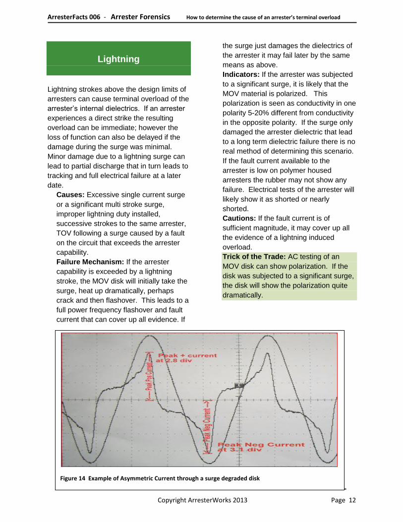
Figure 14 Example of Asymmetric Current through a surge degraded disk
Lightning
Lightning strokes above the design limits of
arresters can cause terminal overload of the
arrester’s internal dielectrics. If an arrester
experiences a direct strike the resulting
overload can be immediate; however the
loss of function can also be delayed if the
damage during the surge was minimal.
Minor damage due to a lightning surge can
lead to partial discharge that in turn leads to
tracking and full electrical failure at a later
date.
Causes: Excessive single current surge
or a significant multi stroke surge,
improper lightning duty installed,
successive strokes to the same arrester,
TOV following a surge caused by a fault
on the circuit that exceeds the arrester
capability.
Failure Mechanism: If the arrester
capability is exceeded by a lightning
stroke, the MOV disk will initially take the
surge, heat up dramatically, perhaps
crack and then flashover. This leads to a
full power frequency flashover and fault
current that can cover up all evidence. If
the surge just damages the dielectrics of
the arrester it may fail later by the same
means as above.
Indicators: If the arrester was subjected
to a significant surge, it is likely that the
MOV material is polarized. This
polarization is seen as conductivity in one
polarity 5-20% different from conductivity
in the opposite polarity. If the surge only
damaged the arrester dielectric that lead
to a long term dielectric failure there is no
real method of determining this scenario.
If the fault current available to the
arrester is low on polymer housed
arresters the rubber may not show any
failure. Electrical tests of the arrester will
likely show it as shorted or nearly
shorted.
Cautions: If the fault current is of
sufficient magnitude, it may cover up all
the evidence of a lightning induced
overload.
Trick of the Trade: AC testing of an
MOV disk can show polarization. If the
disk was subjected to a significant surge,
the disk will show the polarization quite
dramatically.

ArresterFacts 006 - Arrester Forensics How to determine the cause of an arrester’s terminal overload
Copyright ArresterWorks 2013 Page 13
Figure 15 Disk that was cracked in half from power frequency overload
Temporary Overvoltage
A terminal overload caused by a
fundamental power frequency voltage
beyond the capability of the arrester is a
common issue. Arresters are designed to
ride through overvoltages and if properly
dimensioned when installed, they should not
overload in this way. However sometimes
circuit configurations change, or breakers
hang up or other circuit issues result in
elevated voltage beyond the design limit of
the arrester.
Causes: Excessive voltage rise in the
un-faulted phase of a three phase
system, misapplication of the arrester,
change in the neutral configuration of the
system, ferroresonance, loss of neutral
on a system, aging of the disks, and
contact of lines with higher system
voltage.
Failure Mechanism: During a TOV
overload, the voltage across the arrester
rises to a level where the disks conduct
significant power frequency current. The
conduction causes the disk to heat
significantly which in turn lowers the
resistance of the disk leading to more
conduction and ultimate overload. If the
TOV overload is only a few percent high,
then the heating may take place over a
long period.
Indicators: Change in the disk voltage-
current characteristics in both polarities,
cracking of just a few disks in the stack,
flashover of the disks, hole blown in side
of polymer housing, vents opened in
porcelain housed arrester equipped with
vents.
Cautions: Minimal damage to an
arrester during a lightning stroke, disk
aging, or switching surges, can lead to an
overload mode that looks exactly like a
TOV overload.
Trick of the Trade: Removal of the
faulted section of the disk and AC testing
of the chipped parts can reveal TOV
overload.
Figure 16 Section of disk chipped out for testing without influence of faulted section

ArresterFacts 006 - Arrester Forensics How to determine the cause of an arrester’s terminal overload
Copyright ArresterWorks 2013 Page 14
Switching Surge
This overload mode can occur if the
arresters are subjected to surges generated
from switching cap banks, switching or
energizing long lines, switching high voltage
lines, and other sources that exceed the
design limits of the arrester. This overload
condition can only occur on systems above
220kV or on lower voltage systems with
extremely high cap banks installed.
Causes: Restrike or prestrike of
breakers, re or pre strike of capacitor
switches.
Failure Mechanism: See lightning
mechanisms.
Indicators: Numerous small holes in the
aluminum electrode of the disks.
Generally found around the
circumference of the disk electrode.
Polarization of the disk at low levels can
occur.
Cautions: Fault current damage after the
initial overload can disguise the cause.
Disk Aging
Since the initial introduction of the MOV
arrester, it has been accepted that metal
oxide disks can experience a long term
change in their characteristics. This change
in characteristics is referred to as aging. If
the change in characteristics results in more
losses at normal operating voltage, then it
can lead to an arrester failure.
Causes: Improper manufacturing of the
disk.
Failure Mechanism: At normal operating
voltages, the losses gradually increase
leading to internal heating. When the
generated heat exceeds the ability of the
arrester to dissipate the heat into the
environment, it will lead to dielectric
failure and a fault on the system.
Indicators: Hot arrester at operating
temperature, excessive electrical losses
at operating voltage, some disks much
different in losses than others in the
same column of disks, nonlinearity of the
disk reduced as shown on VI trace,
common change in many arresters from
the same vintage, type and
manufacturer.
Cautions: This failure mechanism can
look exactly like a TOV overload.
Less common causes of
Arrester Failure and Overload
External Contamination: This type of
overload can lead to external flashover of
porcelain housings or excessive internal
partial discharge.
Improper MCOV or TOV Rating: The
installation of arresters with an MCOV lower
than the steady state system voltage can
result in arrester overload for what would
appear to be a minor TOV. For example, if
the system has neutral impedance installed,
it requires a higher MCOV arrester than a
grounded neutral, a fault on the system can
lead to arrester overload on the un-faulted
phase.
Unbalanced Electric Field: This is a
failure mode that can occur on an arrester if
the arrester is mounted to close to a ground
plane of another phase. This miss-
installation condition can lead to partial
discharge in the internal volume of the
arrester that can lead to failure. This
condition may also lead to overheating of
the disks due to a voltage imbalance. This
failure may also be caused by the use of
improper grading rings on the arrester.

ArresterFacts 006 - Arrester Forensics How to determine the cause of an arrester’s terminal overload
Copyright ArresterWorks 2013 Page 15
Figure 17 Always take great caution when handling fractured porcelain, the edges are razor sharp
Misalignment of Disk Column: In an
optimal arrester design, a single disk
column within a porcelain housed arrester
should be centered along the length of the
porcelain housing. If the disks are
misaligned during transportation or arrester
installation steady state partial discharge
above the acceptable level may result. If
the column is misaligned during
transportation, it may also result in physical
damage to the edges of the disks that may
also result in partial discharge or internal
flashover of the disk during a lightning
event.
Improper Spring Pressure: (For designs
that require high spring pressure only.) If the
spring in an arrester is not of high enough
pressure, the disk column may become
misaligned during transportation or arrester
installation. This type of defect or
mishandling can lead to a misalignment
issue as discussed above. Also if the
pressure of the spring is too low, partial
discharge or disk damage may occur during
a surge event.
Mechanical Stress: If an arrester is
mounted in such a way that it has excessive
mechanical stress on the unit, it can fail
over long periods of time. This
misapplication generally leads to failure of
the seals which in turn will lead to dielectric
failure of internal components.
Burrs: If a high voltage arrester is
assembled with conductive parts that have
sharp points or edges, partial discharge can
result inside the arrester. This design or
manufacturing defect can lead to dielectric
failure of the arrester.
Insufficient Dielectric Strength: If any of
the materials on the inside of the arrester
have either internal or surface dielectric
strength inadequate for steady state or
impulse states, they can track or flashover.
This manufacturing defect can be
exacerbated by surge events.
Disassembly Considerations
The dissection of an arrester and its
components can be much more difficult if
the internal components are not familiar. It
is recommended that if at all possible; retain
a drawing or sketch of the internal
components before disassembly. If the
arrester is a porcelain housed unit and
cannot be disassembled with bolts, then
simply crack the assembly with a hammer.
The internal spring pressure is not sufficient
to discharge the porcelain more than a few
centimeters. Cover the arrester with a
blanket or cardboard box to contain the
parts.
Cautions: If broken porcelain is involved, it
is highly recommended that thick leather
gloves be used at all times while handling
the broken parts. Shards of porcelain can

ArresterFacts 006 - Arrester Forensics How to determine the cause of an arrester’s terminal overload
Copyright ArresterWorks 2013 Page 16
cause a serious wound to the hand if
touched in the slightest manner. When
dissecting a polymer housed arrester, a
razor knife is most effective.
Also take care not to destroy evidence by
over handling parts. This may be an issue
with a team evaluation and everyone’s
excitement to solve the mystery.
Conclusion
Arrester Forensics is a science that should
be carried out with a plan. If at all possible
have a person on the investigation team
with some arrester experience. Improper
conclusions can cost more than proper ones
at times. The suggestions above should
help you make that plan. If you find you are
stuck and without a conclusion, let it sit for a
day and look at it with new eyes later. This
time delay can be quite useful.
Good luck... and don’t hesitate to contact
Arresterworks with questions in this area.

ArresterFacts 006 - Arrester Forensics How to determine the cause of an arrester’s terminal overload
Copyright ArresterWorks 2013 Page 17
ArresterFacts are a compilation of facts about arresters to assist all stakeholders in the application and
understanding of arresters. All ArresterFacts assume a base knowledge of surge protection of power
systems; however, we always welcome the opportunity to assist a student in obtaining their goal, so
please call if you have any questions. Visit our library of ArresterFacts for more reading on topics of
interest to those involved in the protection of power system at:
About the author:
Jonathan started his career after receiving his Bachelor's degree in Electronic Engineering from The Ohio Institute
of Technology, at Fermi National Accelerator Laboratory in Batavia, IL. As an Engineering Physicist at Fermi Lab, he
was an integral member of the high energy particle physics team in search of the elusive quark.
Wishing to return to his home state, he joined the design engineering team at McGraw Edison (later
Cooper Power Systems) in Olean, New York. During his tenure at Cooper, he was involved in the
design, development, and manufacturing of arresters. He served as Engineering Manager as well as
Arrester Marketing Manager during that time. Jonathan has been active for the last 30 years in the
IEEE and IEC standard associations. Jonathan is inventor/co-inventor on five US patents. Jonathan
received his MBA from St. Bonaventure University.
www.arresterworks.com
+1.716.307.2431
Jonathan Woodworth
ArresterWorks’
Principle Engineer